1
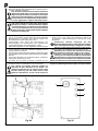
IST DEM ZUR INSTALLATION AUTORISIERTEN PERSONAL VORBEHALTEN - SEULEMENT POUR LE PERSONNEL AUTORISE A L'INSTALLATION - RESERVADO AL PERSONAL ENCARGADO DE LA INSTALACION
RISERVATO AL PERSONALE AUTORIZZATO ALL'INSTALLAZIONE - ONLY FOR INSTALLATION-AUTHORIZED STAFF
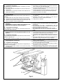
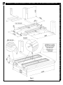
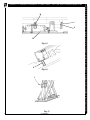
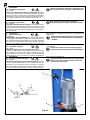
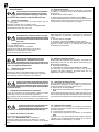
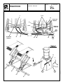
4.18 Montaggio supporto rampa - RAV535 I
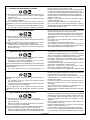
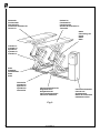
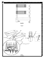
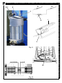
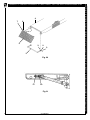
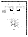
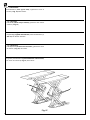
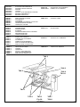
Rif. Fig. 22 - Posizionare il supporto 1 come a figura poi fissare
con gli appositi tasselli (forare con punta Ø10).
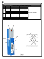
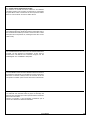
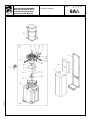
4.19 Fissaggio coperture e centralina - RAV535
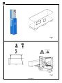
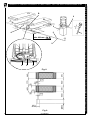
Rif. Fig. 23 - Posizionare le coperture 2-3 e la centralina 1.
Utilizzando i fori esistenti come dime, forare con punta da 9 mm.,
profondità 50 mm. Fissare con tasselli in dotazione e rimontare
il mobile sulla centralina.
4.18 Fitting the ramp support - RAV535 I
Ref. Fig 22 - Place the support 1 as shown in the figure, then
fasten with the relative plugs (drill with bit Ø10).
4.19 Securing covers and control unit - RAV535
Ref. Fig. 23 - Position the covers 2-3 and the control unit 1. Using
the existing holes as templates, drill with a 9 mm bit to a depth
of 50 mm. Fasten with the plugs supplied and refit the unit on the
control unit.
4.18 Montage der Rampenhalterung - RAV535 I
Zu Abb. 22 - Die Halterung 1 gemäss Abbildung positionieren
und mit den passenden Dübeln befestigen (mit einem Ø10
Bohrer bohren).
4.19
Befestigung der Abdeckungen und des
Steuergehäuses - RAV535
Zu Abb. 23. Die Abdeckungen 2-3 und den Schaltschrank 1
positionieren. Die bestehenden Bohrungen als Schablonen
verwenden und mit einem 9 mm Bohrer 50 mm tief bohren. Mit
den mitgelieferten Dübeln befestigen und das Gehäuse wieder
auf den Schaltschrank montieren.
4.18 Montage du support de rampe - RAV535 I
Réf. Fig. 22 - Positionner le support 1 en suivant les indications
de la figure, puis fixer en utilisant les chevilles spéciales (percer
avec une pointe de diamètre 10).
4.19 Fixation des couvertures et de la centrale - RAV535
Réf. Fig. 23. Positionner les protections 2 et 3 et le boîtier de
commande 1. Utiliser les trous existants comme gabarit et
percer avec une pointe de 9 mm, à une profondeur de 50 mm.
Fixer avec les chevilles en dotation et remonter le coffret sur le
boîtier de commande.
4.18 Montaje del soporte rampa - RAV535 I
Ref. Fig. 22 - Coloque el soporte 1 como en la figura, luego
fijar con los tacos apropiados (agujerear con taladro diámetro
10).
4.19 Fijación coberturas y central - RAV535
Ref. Fig. 23. Colocar las tapas 2-3 y la centralita 1. Utilizando
los orificios existentes como plantillas, agujerear con un taladro
de 9 mm., a una profundidad de 50 mm.
Sujetar con los tacos en dotación y volver a montar el mueble
en la centralita.
0579-M080-0
43