1
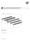
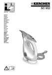
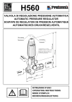
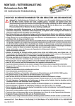
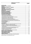
19/09/2006
19.40
Pagina
1
Rev:4 09/2006 - Cod: A4516_6190
CH_GARDA_REV4_09-2006.qxd
MOTORI TUBOLARI
TUBULAR MOTORS
ROHRMOTOREN
MOTEURS TUBULAIRES
MOTORES TUBULARES
Serie
Series
Reihe
CHERUBINI S.p.A.
SISTEMI DI MANOVRA PER LA PROTEZIONE SOLARE
BLUE GARDA
BLUE ROLL
BLUE ROLL EASY
BLUE MICRO
MOTION SYSTEMS FOR SOLAR PROTECTION
MOTEURS ET ACCESSOIRES POUR STORES ET FERMETURES
ANTRIEBSSYSTEME FÜR DEN SONNENSCHUTZ
SISTEMAS DE ACCIONAMIENTO PARA PROTECCION SOLAR
ISTRUZIONI - INSTRUCTIONS - ANLEITUNGEN
INSTRUCTIONS - INSTRUCCIONES
CH_GARDA_REV4_09-2006.qxd
19/09/2006
19.40
Pagina
3
ISTRUZIONI PER LA SICUREZZA
ISTRUZIONI PER L’ USO E PER L’ INSTALLAZIONE
ITA
ATTENZIONE
PER LA SICUREZZA DELLE PERSONE È IMPORTANTE SEGUIRE QUESTE ISTRUZIONI.
CONSERVARE QUESTE ISTRUZIONI.
L’ INSTALLAZIONE NON CORRETTA PUÒ CAUSARE GRAVI FERITE.
NO
NO
NO
NO
NO
- I motori serie “BLUE 45” sono stati realizzati per automatizzare il movimento di
avvolgibili e tende da sole ogni altro uso è improprio.
- Non sottoporre il motore tubolare a schiacciamenti, urti, cadute o contatto con
liquidi di qualunque natura; non forare né applicare viti per tutta la lunghezza del
tubolare.
- Il diametro minimo del tubo in cui il motore della serie “BLUE 45” può essere
installato non deve essere inferiore a 50 mm.
- Se il motore viene utilizzato per la movimentazione di tende da sole, rispettare la
distanza orizzontale di sicurezza di almeno 40 cm fra la tenda completamente
aperta e qualsiasi oggetto permanente.
- La scelta del motore, nella sua applicazione di utilizzo, deve essere compatibile
con i dati di targa indicati sul motore stesso.
- Il motore tubolare è progettato per un tempo massimo di funzionamento in
continuo di 4 minuti.
- Per manutenzioni e riparazioni rivolgersi a personale tecnico competente.
- L’installazione deve essere eseguita da personale tecnico nel pieno rispetto delle
norme di sicurezza, soprattutto per quanto riguarda i collegamenti elettrici.
- Danni provocati da forzature, manomissioni o collegamenti errati, non sono
coperti da garanzia.
- NON permettere ai bambini di giocare con i dispositivi di comando fissi e mobili.
- Prima di ogni intervento di manutenzione, installazione o pulizia delle finestre
scollegare l’alimentazione del motore.
- Prima di installare il motore di movimentazione, togliere i cavi superflui e
disabilitare eventuali apparecchiature non necessarie per il funzionamento del
motore stesso.
- Controllare spesso l’impianto per scoprire eventuali sbilanciamenti e segni di
usura o danni a cavi e molle. NON utilizzate l’impianto se è necessaria una
riparazione o una regolazione, ma chiamare il centro assistenza.
- Proteggere le parti mobili del motore se installate ad una altezza inferiore a 2,5m
dal pavimento o da altro livello da cui accedere ad esso.
- L’interruttore tenuto in tensione manualmente deve essere fissato in vista
dell’apparecchio, ma lontano da parti mobili ed a un’altezza superiore a 1,5 m.
- Rispettare scrupolosamente i collegamenti previsti, in caso di dubbi NON
procedere casualmente, ma consultare personale tecnico competente.
- A tapparella o tenda da sole in movimento tenere lontano le persone dal raggio
d’azione.
- Dispositivi di connessione, supporti e adattatori, vengono forniti separatamente.
Per l’uso e la scelta consultare il catalogo “Motori Tubolari”.
- In caso di danneggiamento del cavo di alimentazione rivolgersi al centro di
assistenza o a personale tecnico di competenza.
2
3
CH_GARDA_REV4_09-2006.qxd
19/09/2006
19.40
Pagina
5
COLLEGAMENTI ELETTRICI
marrone
1-1-marrone
2nero
2- nero
3azzurro
3- azzurro
4giallo verde
4- giallo-verde
230 V 50 Hz
- Per evitare situazioni di pericolo o malfunzionamento, gli elementi elettrici di comando
collegati al motore devono essere dimensionati in base alle caratteristiche elettriche del
motore stesso.
- A monte del circuito prevedere un sezionatore bipolare con distanza di apertura dei contatti
di almeno 3 mm.
- I selettori per l’inversione del senso di rotazione del motore devono essere muniti di
interblocco meccanico.
2
- Per modificare il senso di rotazione, invertire i conduttori marrone e nero.
- NON collegare due o più motori sullo stesso selettore (collegamento in parallelo). In caso di
1
accoppiamento di due motori utilizzare solamente selettori a più poli.
- NON collegare due o più selettori sullo stesso motore.
- In caso di montaggio all’esterno, il cavo di alimentazione del motore
deve essere posato in un tubo di protezione di materiale resistente alla
luce solare.
4
3
4
5
ITA
CH_GARDA_REV4_09-2006.qxd
19/09/2006
19.40
Pagina
7
REGOLAZIONE DEI FINECORSA
PREPARAZIONE DEL MOTORE
ADATTATORE GHIERA FINECORSA
PULEGGIA DI TRAINO
I motori tubolari Blue Garda prevedono un sistema di finecorsa elettromeccanici che
interrompono l’alimentazione quando la tenda o l’avvolgibile raggiungono il limite di apertura
e di chiusura. Per regolare questi limiti ed adattarli al caso specifico è sufficiente agire sulle due
viti di regolazione posizionate sulla testa del motore. I limiti di finecorsa sono preimpostati a
circa 3 giri di rullo.
1. Per individuare quale delle due viti utilizzare basta osservare il senso di
rotazione della ghiera finecorsa: se la ghiera finecorsa trascinata dal rullo
ruota nella direzione A, utilizzare la vite di regolazione A per regolare il finecorsa in quel senso. Se la direzione è opposta (B) utilizzare la vite di regolazione B.
GHIERA FINECORSA
Fig. 1
ITA
2. Azionare la tenda o l’avvolgibile nella direzione in cui si vuole regolare il
primo finecorsa. Dopo qualche giro il motore si ferma nel punto finecorsa
preimpostato.
1. Inserire l’adattatore sulla ghiera finecorsa
facendo combaciare la scanalatura con la tacca di
riferimento e spingere fino alla battuta.
3. Ruotare la vite di regolazione adeguata al senso di rotazione (punto 1)
nella direzione + fino al raggiungimento della posizione desiderata.
4. Invertire il senso di rotazione del motore e regolare il secondo finecorsa.
2. Montare la puleggia di traino sul perno del
motore fino allo scatto della molla di fermo.
VITI DI
REGOLAZIONE
B
Fig. 2
A
A
3. Introdurre completamente il motore nel tubo di
avvolgimento.
Fig. 3
NB: Nel caso di tubi con profilo tondo la puleggia di traino deve essere fissata al tubo, questa
operazione è a carico dell’installatore. Per altri profili di tubo il fissaggio è facoltativo.
GHIERA FINECORSA
B
6
7
CH_GARDA_REV4_09-2006.qxd
19/09/2006
19.40
Pagina
9
SECURITY INSTRUCTIONS
INSTRUCTIONS FOR USE AND INSTALLATION
GB
WARNING
FOR PEOPLE’S SAFETY, IT IS IMPORTANT TO FOLLOW THESE INSTRUCTIONS.
KEEP THESE INSTRUCTIONS.
A WRONG INSTALLATION CAN CAUSE SEVERE INJURES.
NO
NO
NO
NO
NO
- “BLUE 45” series motors have been designed only to automatize the movement
of roller shutters and awnings. Any other use is improper.
- Do not squash, crush, drop or wet the tubular motor with any kind of liquid
material; do not pierce and do not apply any screw along the tubular.
- The motor of series “BLUE 45” must be installed in a tube with a minimum
diameter of 50 mm.
- If the motor is used to move awnings, keep a security horizontal distance of 40
cm between the fully opened awning and any permanent object.
- The choice of the motor, in its use application, must be compatible with the rating marked on the motor itself.
- The tubular motor has been designed to work nonstop for a maximum
of 4 minutes.
- Professional technicians only must perform maintenance and repairs.
- Professional technicians only must perform installation, complying with all
security instructions, especially those regarding electrical connections.
- The warranty is not applicable to any damage caused by misuse, straining,
tampering on wrong connections.
- DO NOT permit children to play with the fixed or mobile control devices.
- Before each intervention in maintenance, installation or cleaning of the windows
switch off the motor power supply.
- Before installing the handling motor, take away the unnecessary cables and
disconnect those equipment not required for the working of the motor itself.
- Often ceck the plant to find out any unbalances and signs of wear and tear or
damages to cables and springs. DO NOT use the plant, if it is necessary a repair
or an adjustment, but call the assistance centre.
- Protect the mobile parts of the motor if they have been installed at a height lower
than 2,5m from the floor or another level.
- The switch, kept manually in tension, must be fixed near the equipment, but far
from the mobile parts and at a height at least higher than 1.5m.
- During connection follow the instructions thoroughly. If you have any doubt,
NEVER act at random but consult competent technicians.
- Keep away from moving awnings and rolling shutters.
- Connection devices, supports and adaptors are not supplied with our motors but
separately . For use and choice consult the catalogue “Tubular motors”.
- In case the cable is damaged please call the assistance center or qualified
technical staff.
8
9
CH_GARDA_REV4_09-2006.qxd
19/09/2006
19.40
Pagina
11
GB
ELECTRICAL CONNECTIONS
marrone
1-1-brown
nero
2-2-black
azzurro
3-3-light
blue
giallo verde
4-4-yellow-green
230 V 50 Hz
- To prevent any danger or malfunction, the size of electrical control components connected
to the motor must be compatible with the electrical features of the motor.
- Arrange a bipolar knife switch with opening distance of the contacts of at least
3 mm before the circuit
- The selectors inverting the direction of rotation of the motor must be provided with
mechanical interlocking.
- Invert the brown and the black conductor to change the direction of rotation.
- NEVER connect two or more motors to the same selector (parallel connection) If you couple
2
two motors, use multi-poles selectors only.
1
- NEVER connect two or more selectors to the same motor.
- For out-door installation protect the feed-cable with a protection tube made of a light resistant
material.
10
3
4
11
CH_GARDA_REV4_09-2006.qxd
19/09/2006
19.40
Pagina
13
HOW TO PREPARE THE MOTOR
STOP RING NUT ADAPTOR
DRIVING PULLEY
ADJUSTEMENT OF THE LIMIT SWITCH
Blue Garda tubular motors are provided with a system of electromechanical limit switches that
stop the feed when the awning or the rolling shutter get to the maximum opening or closing
limits. To adjust these limits and adapt them to any need, simply screw or unscrew the two
adjusting screws on the motor head. The limits of the limit switches are preset at about three
turns of the roller.
1. To decide which adjusting screw to fix, simply watch the direction of
rotation of the stop ring nut: if the stop ring nut pulled by the roller goes in
direction A, use the adjusting screw A to set the limit switch in that
direction. If it goes to the opposite direction (B), use the adjusting screw B.
STOP RING NUT
1
GB
2. Start up the awning or the roller shutter in the direction in which you wish
to set the first limit switch. After a few turns the motor will stop on the
preset stop.
1. Insert the adaptor in the stop ring nut mating
the groove with the reference notch and push till
they touch.
3. Screw the adjusting screw suited to the direction (see point 1.) in
direction “+” till it gets to the chosen position.
4. Invert the engine sense of direction and set the second limit switch.
2. Fix the driving pulley on the motor pin until
the stop pin clicks.
ADJUSTING
SCREWS
B
2
A
A
3. Insert the motor fully in the rolling tube.
3
NB: If you use tubes with a round form, the driving pulley must be fixed to the tube, and the
installation is to be paid by the person who installs the system. For other forms the fixing is optional.
STOP RING NUT
B
12
13
CH_GARDA_REV4_09-2006.qxd
19/09/2006
19.40
Pagina
15
SICHERHEITSVORSCHRIFTEN
ANLEITUNG ZUR BENUTZUNG UND MONTAGE
D
ACHTUNG
FÜR DIE SICHERHEIT DER PERSONEN IST ES WICHTIG DEN VORLIEGENDEN
ANLEITUNGEN ZU FOLGEN UND DIESE AUFZUBEWAHREN.
NEIN
NEIN
NEIN
NEIN
NEIN
EIN FALSCHER ANSCHLUSS DER MOTOREN, KANN SCHWERE
VERLETZUNGEN HERVORRUFEN.
- Die Motoren der Reihe “BLUE 45“ sind ausschließlich für den Antrieb von
Rollladen und Markisen konzipiert. Jede andere Nutzung ist unsachgemäß.
- Den Rohrmotor auf der ganzen Länge; keinem Druck oder Schlägen aussetzen;
mit keiner Flüssigkeit in Verbindung bringen; nicht anbohren sowie auf der
ganzen Länge mit keinerlei Schrauben versehen.
- Der minimalste Einbaudurchmesser, worin die Motoren der Serie “BLUE 45”
eingebaut werden, darf 50mm nicht unterschreiten.
- Bei Verwendung des Motors bei Markisen einen horizontalen Sicherheitsabstand
von 40cm, zwischen ausgefahrenen Armen und jeglichem festen Gegenstand,
einhalten.
- Die Auswahl des richtigen Motors muss mit den Daten auf dem Motorenetikett
kompatibel sein.
- Der Motor wurde für eine maximale Einschaltdauer von 4 Minuten entwickelt.
- Bei Service und Reparaturen, sich an technisch geschultes Fachpersonal wenden.
- Unter Einhaltung der Sicherheitsnormen muss die Installation bezüglich der
elektrischen Anschlüsse, von geschultem Fachpersonal ausgeführt werden.
- Die durch unsachgemäße Handhabung oder irrtümlichen Anschluss hervorgerufene
Schäden sind von der Garantie ausgeschlossen.
- Im Falle einer Beschädigung des Netzkabels, wenden Sie sich an das nächste
Servicecenter oder zur Behebung technisch geschultes Fachpersonal anfordern.
- Kindern das Spielen an den festen oder beweglichen Schaltelementen NICHT
- zulassen.
Vor jedem Eingriff; Installation, Instandhaltung, Fensterreinigung oder ähnliches,
- ist die Stromzufuhr zum Motor zu unterbrechen.
Vor der Montage des Rohrmotors überzählige, Kabel und jede andere, zur
- Funktion des Motors nicht notwendige Vorrichtung entfernen.
Die Anlage ist häufig auf Abgleichfehler oder auf Anzeichen von Verschleiß,
beschädigte Kabel und Federn zu überprüfen. Die Anlage NICHT verwenden, falls
Reparaturen oder Justierungen notwendig sind, und zur Behebung geschultes
- Fachpersonal anfordern.
Bewegliche Teile von Antrieben, die unter einer Höhe von 2,5m ab Boden oder
- einer von anderer Ebene betrieben werden, müssen geschützt sein.
Unter Spannung stehende Schalter müssen fern von beweglichen Gegenständen
auf einer Mindesthöhe von 1,5m montiert werden und vom Antrieb her sichtbar
- sein.
Die vorgesehenen Anschlüsse vorbehaltlos einhalten, im Zweifelsfall NICHT ohne
- weiteres vorgehen, sondern geschultes Fachpersonal beiziehen.
- Bei fahrenden Rollladen oder Markisen, Personen fernhalten.
Anschlussvorrichtungen, Motorlager und Adapter werden separat geliefert. Zur
richtigen Auswahl des Motors den Katalog „Rohrmotoren“ konsultieren.
14
15
CH_GARDA_REV4_09-2006.qxd
19/09/2006
19.40
Pagina
17
ELEKTRISCHE ANSCHLÜSSE
marrone
1-1-Braun
2nero
2- Schwarz
3azzurro
3- Blau
4giallo verde
4- Gelb-Grün
230 V 50 Hz
- Um Gefahrensituationen oder Fehlfunktionen zu vermeiden, müssen alle mit den Motoren
verbundenen Steuerelemente auf die Leistung des entsprechenden Motors abgestimmt sein.
- Vom Netz muss eine allpolige Trennung, mit Kontaktöffnungsweite von mindestens 3mm
pro Pol, vorhanden sein.
- Die Drehrichtungsschalter müssen mit einer mechanischen Zwischenschaltung versehen
sein.
- Zur Umkehrung der Drehrichtung, das Braune und Schwarze Kabel umhängen.
2
- Bei Anwendung im Außenbereich, muss die Anschlussleitung in ein schützendes Rohr aus
sonnenlichtfestem Material verlegt werden.
1
- Nicht zwei oder mehr Motoren an einen Schalter anschließen. (Keine Parallelschaltung!). Bei
Verwendung von zwei oder mehr Motoren, mehrpolige Schalter verwenden.
- Nicht zwei oder mehr Schalter an einem Motor anschließen.
- Bei Anwendung im Außenbereich, muss die Anschlussleitung in ein
3
4
schützendes Rohr aus sonnenlichtfestem Material verlegt
werden.
16
17
D
CH_GARDA_REV4_09-2006.qxd
19/09/2006
19.41
Pagina
19
EINFACHE INSTALLATION
LAUFRING - MITNEHMER
ANTRIEBSADAPTER
EINSTELLUNG DER ENDABSCHALTUNG
D
Die Rohrmotoren der Reihe Blue Garda sind mit einer elektromechanischen Endabschaltung
ausgestattet die bei Erreichung der Endposition, die Stromzufuhr unterbricht. Um die
Endpositionen einzustellen und diese der entsprechenden Rollladen oder Markisedimension
anzupassen, genügt es mit dem mitgelieferten flexiblen Einstellhilfe an den beiden
Einstellschrauben am Motorkopf zu drehen. Im Auslieferzustand ist die Endabschaltung bei
ca. 3 Rohrumdrehungen voreingestellt.
1. Bei Links- oder Rechtseinbau gilt grundsätzlich:
- Stellschraube A zur Einstellung der Endposition der Drehrichtung A.
- Stellschraube B zur Einstellung der Endposition der Drehrichtung B.
ENDANSCHLAGRING
2. Den Motor in die gewünschte Richtung laufen lassen um die erste
Endposition einzustellen. Der Motor schaltet gemäss der Voreinstellung nach
ca. 3 Umdrehungen ab.
1
1. Den Laufring/Mitnehmer ganz auf den
Nuteinlauf des Endanschlagrings am Motor
schieben.
2. Den Antriebsadapter bis zum Einrasten der
Feder aufstecken.
3. Nun mit der Einstellhilfe an der entsprechenden Einstellschraube im
Uhrzeigersinn (+) zur Erreichung der Endposition drehen.
4. Um die zweite Endposition einzustellen in die entgegengesetzte Richtung
laufen lassen und die Schritte wiederholen.
EINSTELLSCHRAUBEN
B
2
A
A
3. Den Motor vollständig in die Rollladenwelle
oder Markisennutrohr einschieben.
3
Bem: Bei Rundrohren muss der Antriebsadapter am Rohr befestigt werden. Diese Operation geht
zu lasten der Installateurs. Bei anderen Rohrprofilen ist die Befestigung fakultativ.
ENDANSCHLAGRING
B
18
19
CH_GARDA_REV4_09-2006.qxd
19/09/2006
19.41
Pagina
21
CONSIGNES DE SÉCURITÉ
INSTRUCTIONS D’UTILISATION ET D’INSTALLATION
F
ATTENTION
POUR LA SECURITE DES PERSONNES IL EST IMPORTANT DE RESPECTER LES
INSTRUCTIONS SUIVANTES. CONSERVER CES INSTRUCTIONS.
UNE INSTALLATION INCORRECTE PEUT CAUSER DES BLESSURES GRAVES
NON
NON
NON
NON
NON
- Les moteurs série “BLUE 45” sont conçus pour la motorisation de volets roulants
et stores, tout autre utilisation doit faire l’objet d’un accord de nos
services techniques.
- Ne pas écraser, frapper ou faire tomber le moteur tubulaire. Ne pas percer ou
appliquer de vis sur toute la longueur du moteur tubulaire. Ne pas exposer aux
intempéries, ni à aucun genre de liquide.
- Le moteur série “BLUE 45” doit être installé dans un tube de 50 mm minimum.
- Respecter la distance de securité de 40 cm entre le store complètement ouvert et
tout objet fixe.
- Le choix du moteur, dans son application, doit être compatible avec les données
indiquées sur le moteur même.
- Le moteur tubulaire a été conçu pour un usage intermittent et pour un fonctionnement continu de 4 minutes maximum.
- Réparations et démontages ne sont autorisés que dans nos ateliers ou en station
technique agréée.
- L’installation doit être faite par du personnel technique qualifié en respectant les
normes de securité, surtout pour ce qui concerne les branchements électriques.
- Les dégâts dus à une mauvaise installation, mauvaise utilisation, défaut
d’entretien, ou un mauvais branchement ne sont pas couvert par la garantie.
- En cas de dégât du câble d’alimentation, s’adresser à nos ateliers ou à une
station technique agréée pour remise en état.
20
- NE PAS permettre aux enfants de jouer avec les dispositifs de commandes fixes
ou mobiles.
- Avant toute manutention, installation ou nettoyage des fenêtres couper
l’alimentation du moteur tubulaire.
- Avant d’installer le moteur, enlever les câbles superflus et débrancher tout
appareil non nécessaire pour le fonctionnement du moteur.
- Contrôler souvent l’installation afin de découvrir d’éventuels déséquilibres et
signes d’usure ou dégâts aux câbles et aux ressorts, NE PAS utiliser l’installation
s’il y a besoin d’une réparation, mais appeler le centre d’assistance.
- Protéger les parties mobiles du moteur s’il est installé à une hauteur inférieure de
2,5 mètres du plancher ou d’autre niveau (surface) duquel on peut y accéder.
- L’interrupteur « sous tension » doit être fixé à une hauteur minimum de 1,5 mètre,
à distance suffisante de tout objets en mouvement et à portée de vue du store
ou du volet roulant commandé.
- Respecter les instructions données, en cas de doute consulter nos services
techniques agréés.
- Pendant l’ouverture et la fermeture du store ou du volet roulant garder les
personnes éloignées du rayon d’action.
- Les dispositifs de connections, les supports et adaptations viennent en plus
et sont fournis séparément. Pour l’utilisation et le choix veuillez consulter le
catalogue "Moteurs tubulaires” ou nos services techniques agréés.
21
CH_GARDA_REV4_09-2006.qxd
19/09/2006
19.41
Pagina
23
CONNEXIONS ÉLECTRIQUES
F
marrone
1-1-marron
nero
2-2-noir
azzurro
3-3-bleu
giallo verde
4-4-jaune-vert
230 V 50 Hz
- Pour éviter toutes situations de danger ou un mauvais fonctionnement, les éléments
électriques de commande reliés au moteur doivent être appropriés en fonctions des
caractéristiques du moteur.
- Le circuit alimentant le moteur doit être pourvu d’un dispositif de coupure omnipolaire
ayant une distance d’ouverture d’au moins 3 mm.
- Les touches d’inversion du sens de rotation du moteur doivent être pourvues d’un blocage
mécanique (pour ne pas alimenter la Montée/Descente en même temps).
2
- Pour modifier le sens de rotation, inverser les câbles Marron et Noir.
- NE PAS relier 2 ou plusieurs moteurs au même inverseur. En cas d’un branchement de
1
2 moteurs sur un seul inverseur utiliser impérativement un inverseur de type bipolaire.
- NE PAS relier 2 ou plusieurs inverseurs au même moteur.
- En cas d’une utilisation extérieure, le câble devra être protégé par une
gaine, goulotte ou autre tube de protection en matériel résistant à la
lumière du soleil.
22
3
4
23
CH_GARDA_REV4_09-2006.qxd
19/09/2006
19.41
Pagina
25
PRÉPARATION DU MOTEUR
BAGUE D’ADAPTATION DE FIN DE COURSE
ROUE D’ENTRAÎNEMENT
RÉGLAGE DU FIN DE COURSE
Les moteurs tubulaires “ Blue Garda “ ont un système de fin de course électromécanique qui
interrompe la tension de service 230 V quand le store ou le volet arrivent à ses fins de courses.
Pour régler ces limites, agissez sur les deux vis de réglage positionnées sur la tête du moteur.
Les limites de fin de course sont préréglés en usine à plus ou moins trois tours dans chaque sens.
1. Pour savoir laquelle des 2 vis utiliser, il suffit de regarder le sens de rotation du volet ou du store : si le tube tourne dans la direction A, il faudra
utiliser la vis A pour régler le fin de course dans ce sens. Si la direction est
opposée (B) il faudra utiliser la vis B.
COURONNE DE FIN DE COURSE
Fig. 1
F
2. Faire fonctionner le store ou le volet roulant dans la direction dans laquelle on veut régler le premier fin de course. Après quelques tours le moteur
s’arrête au point limite préréglé.
1. Insérer la bague d’adaptation sur la
couronne de fin de course en insérant l’encoche
dans le repère rainuré et pousser jusqu’en
butée.
2. Monter la roue sur l’axe de sortie du moteur
jusqu’à enclenchement du ressort d’arrêt.
3. Tourner la vis de réglage relative au sens de rotation (voir point 1) en
direction “ + “ jusqu’à arriver à la position désirée.
4. Inverser le sens de rotation du moteur et régler le deuxième fin de course.
VIS DE
RÉGLAGE
B
Fig. 2
A
A
3. Introduire complètement le moteur dans le
tube.
Fig. 3
NB: En cas de tube rond ou lisse la roue doit être fixée au tube, cette opération est à la charge
du monteur. Pour les autres tubes la fixation est facultative mais fortement conseillée.
24
COURONNE DE
FIN DE COURSE
B
25
CH_GARDA_REV4_09-2006.qxd
19/09/2006
19.41
Pagina
27
INSTRUCCIONES DE SEGURIDAD
INSTRUCCIONES DE USO E INSTALACION
E
ATENCIÓN
PARA LA SEGURIDAD DE LAS PERSONAS ES IMPORTANTE SEGUIR ESTAS
INSTRUCCIONES. CONSERVAR ESTAS INSTRUCCIONES.
LA INSTALACCIÓN NO CORRECTA PUEDE CAUSAR GRAVES HERIDAS.
NO
NO
NO
NO
NO
- Los motores serie “BLUE 45” han sido realizados para automatizar el movimiento
de persianas enrollables y toldos; cualquier otro tipo de uso
es impropio.
- No someter el motor tubular a aplastamientos, golpes, caídas o contacto con
líquidos de cualquier naturaleza; no perforar ni aplicar tornillos a lo largo de todo
el tubo.
- El diámetro mínimo del tubo donde se puede instalar el motor de la serie
“BLUE 45”, no tiene que superar los 50 mm.
- Si el motor se utiliza para la manejo de toldos, respetar la distancia horizontal de
seguridad de al menos 40 cm entre el toldo completamente abierto y cualquier
objeto permanente.
- La elección del motor, en su aplicación de utilización, tiene que ser compatible
con los datos indicados en la placa de propio motor.
- El motor tubular ha sido ideado para un tiempo máximo de funcionamiento
continuo de 4 minutos.
- Para el mantenimiento y reparaciones recurrir a personal técnico competente.
- La instalación tiene que ser efectuada por personal técnico con pleno respeto de
las normas de seguridad, sobre todo en lo referente a las conexiones eléctricas.
- Daños provocados da forzamientos, manumisiones o conexiones equivocadas, no
están cubiertos con la garantía.
- En el caso de rotura o daños en el cable de alimentación del motor, dirigirse al
centro de asistencia o a personal técnico especializado.
- NO permitir que los niños jueguen con los dispositivos de mando fijos y móviles.
- Antes de cualquier operación de mantenimiento, instalación o limpieza de las
ventanas desconectar la alimentación del motor.
- Antes de instalar el motor de desplazamiento, eliminar los cables superfluos y
deshabilitar eventuales instrumentaciones no necessarias para el funcionamiento
de dicho motor.
- Controlar a menudo el sistema para descubrir eventuales inestabilidades y
señales de desgaste o daños a cables y resortes. Si fuera necesaria una reparación
o regularización NO utilizar el sistema y llamar al centro de asistencia.
- Proteger las partes móviles del motor si se instalan a una altura inferior de 2,5m
del suelo u otro nivel que sirva para acceder a dicho motor.
- El interruptor de tensión manual debe estar fijado a la vista del aparato, pero
lejos de cualquier parte móvil y a una altura superior de 1,5 m.
- Respetar escrupolosamente las conexiones previstas, en caso de dudas NO
proseguir casualmente sino consultar el personal técnico competente.
- Cuando la persiana enrollable o toldo esté en movimiento mantener lejos las personas del radio de acción.
- Dispositivos de conexión, soportes y adaptadores, se suministran a parte. Para el
uso y la elección consultar el catálogo “Motores Tubolares”.
26
27
CH_GARDA_REV4_09-2006.qxd
19/09/2006
19.41
Pagina
29
CONEXIONES ELÉCTRICAS
marrone
1-1-marrón
2nero
2- negro
3azzurro
3- azul
4giallo verde
4- amarillo-verde
230 V 50 Hz
- Para evitar situaciones de peligro o un mal funcionamento, los elementos eléctricos
de mando conectados al motor tienen que ser dimensionados según las características
eléctricas del propio motor.
- En la parte alta del circuíto es necesario preveer un seccionador bipolar con distancia de
abertura de los contactos de al menos 3 mm.
- Los selectores para la inversión del sentido de rotación del motor tienen que estar provistos
de interbloqueo mecánico.
2
- Para modificar el sentido de rotación, invertir los conductores marrón y negro.
- No conectar más de un motor en el mismo selector (conexión en paralelo). En caso de
acoplamiento de dos motores utilizar solamente selectores de más polos.
1
- No conectar más de un selector en el mismo motor.
- En caso de montaje en el exterior, el cable de alimentación del motor
tiene que ser colocado en un tubo de protección de material resistente a
la luz solar.
28
3
4
29
E
CH_GARDA_REV4_09-2006.qxd
19/09/2006
19.41
Pagina
31
PREPARACIÓN DEL MOTOR
ADAPTATOR ABRAZADERA FINAL DE CARRERA
POLEA DE ARRASTRE
REGULACIÓN DE LOS FINALES DE CARRERA
Los motores tubulares Blue Garda preven un sistema de final de carrera electromecánicos que
interrumpen la alimentación cuando el toldo o la persiana
enrollable alcanzan el límite de abertura y de cierre. Para regular estos límites y adaptarlos al
caso específico es suficiente accionar los dos tornillos de regulación colocados en la cabeza del
motor. Los límites de final de carrera están programados a unos 3 giros del rodillo.
ABRAZADERA FINAL
DE CARRERA
Fig. 1
E
1. Para descubrir cual de los dos tornillos hay que utilizar basta observar el
sentido de rotación de la abrazadera final de carrera: si la abrazadera final
de carrera arrastrada por el rodillo gira en la dirección A, utilizar el tornillo
de regulación A para ajustar el final de carrera en ese sentido. Si la dirección
es opuesta (B) utilizar el tornillo de regulación B.
2. Accionar el toldo o la persiana enrollable en la dirección en la que se
quiere regular el primer final de carrera. Después de girar varias veces el
motor se para en el punto final de carrera programado precedentemente.
1. Introducir el adaptador en la abrazadera final
de carrera haciendo coincidir la estría con la
muesca de referencia y empujar hasta el tope.
3. Girar el tornillo de regulación adapta al sentido de rotación (punto 1) en
la dirección + hasta alcanzar la posición deseada.
4. Invertir el sentido de rotación del motor y ajustar el segundo final de
carrera.
2. Montar la polea de arrastre en el perno del
motor hasta el clic del resorte de bloqueo.
TORNILLOS DE
REGULACIÓN
B
Fig. 2
A
A
3. Introducir completamente el motor en el
tubo de arrollamiento.
Fig. 3
NB: en caso de tubos con perfil redondo la polea de arrastre se tiene que fijar al tubo, esta
operación es a cargo del instalador. para otros perfiles de tubo el ajuste es facultativo.
ABRAZADERA FINAL DE CARRERA
B
30
31