1
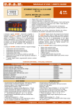
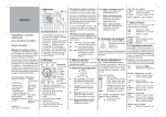
E.S.A.M.
MANUALE D’USO / USER’S GUIDE
ANALIZZATORE DI RETE
DI PRECISIONE
E1100
HIGH ACCURACY
NETWORK ANALYZER
L’analizzatore di rete E1100, interamente progettato e sviluppato da
ESAM, è costruito per soddisfare tutte le moderne esigenze di
misura e controllo dei parametri elettrici di una rete trifase.
L’elevata precisione di misura lo rende particolarmente adatto per
impieghi in laboratori, sistemi di acquisizione e di regolazione, ecc.
Basato su un microprocessore di ultima generazione, è dotato di un
circuito di misura con cambio portata automatico e di una interfaccia
seriale RS485 veloce.
L’accurato dimensionamento di ogni componente (es. circuiti
stampati omologati UL) e la taratura con strumenti certificati SIT
garantiscono la massima precisione ed affidabilità in ogni
condizione di utilizzo.
Le principali caratteristiche dell’analizzatore di rete E1100 sono le
seguenti:
elevata precisione di misura: 0.2% della lettura dal 5 al 100%
del campo di misura, frequenza AC da 45 a 65 Hz
elevate prestazioni con forme d’onda distorte: 256 campioni per
periodo di rete AC, banda passante di ingresso 2 kHz (-3dB)
multiportata automatico (7 campi di misura per tensioni e
correnti, G = 1,2,4,8,16,32,64)
calcolo ogni mezzo periodo di rete AC di tensioni di fase e
concatenate RMS, correnti di fase RMS e corrente di neutro
RMS, correnti e tensioni istantanee di picco, frequenza, potenze
attive, reattive e apparenti, fattore di potenza di ciascuna fase e
del sistema trifase
media valori letti programmabile da mezzo periodo di rete AC
(minimo) a 1 secondo (max)
analisi armonica di tensioni e correnti di fase, calcolo distorsione
armonica totale (THD)
rilevazione valori minimi e massimi di tutte le misure
interfaccia seriale isolata RS485, 1200 … 115200 baud,
protocollo Modbus RTU
inserzione trifase con 3 TA o 2 TA (ARON) o monofase con 1 TA
rapporti TA e TV configurabili
montaggio su profilato DIN EN50022-35
The network analyzer E1100, entirely designed and developed by
ESAM, is built to comply with all the modern requirements of
measure and control of electrical parameters in a 3-phase network
Due to its high measuring accuracy, E1100 is particularly suited for
laboratory applications, sophisticated data acquisition and control
systems, etc.
It features a microprocessor of the latest generation, an autoranging
analog input stage and a fast RS485 serial interface.
The careful choice of every component (e.g. UL recognized printed
circuits) and the calibration with EAL.SIT certificated devices,
provide the highest precision and reliability in every condition of use.
The main features of the network analyzer E1100 are the following:
high accuracy: 0.2% of reading, from 5% to 100% of measuring
range, AC frequency 45 to 65 Hz
high accuracy with distorted waveforms: 256 samples every AC
period, 2kHz analog input bandwidth (-3bB)
autorange (7 ranges for input voltages and currents, G =
1,2,4,8,16,32,64)
calculation every half AC period of phase and linked RMS
voltages, phase RMS currents and neutral RMS current,
instantaneous peak voltages and currents, frequency, active,
reactive and apparent powers, power factor of each phase and
of 3-phase system
averaging of measured values programmable from half AC
period (min) to 1 second (max)
Harmonic analysis of phase voltages and currents, calculation of
total harmonic distortion (THD)
Min and max values of every reading
RS485 insulated serial interface, 1200 ... 115200 baud,
Modbus RTU protocol
3-phase connection with 3 CT or 2 CT (ARON) or single-phase
with 1 CT
configurable CT and VT ratios
rail DIN EN50022-35 mounting
Grandezze misurate
Measured Variables
Unità di misura
Measured units
Tensioni di fase / Phase Voltages
Tensioni concatenate / Linked Voltages
Tensioni istantanee di picco / Instantaneous peak voltages
Tensione concatenata media / Linked average Voltage
Correnti / Currents
Correnti istantanee di picco / Instantaneous peak currents
Corrente di neutro / Neutral current
Corrente media / Average current
Distorsione armonica / Total harmonic distortion
Potenze attive / Active Powers
Potenza attiva totale / Total Active Power
Potenze reattive / Reactive Powers
Potenza reattiva totale / Total Reactive Power
Potenze apparenti / Apparent Powers
Potenza apparente totale / Total Apparent Power
Fattore di potenza di fase / Phase power factor
Fattore di potenza totale / 3-phase power factor
Frequenza / Frequency
Ampiezza armoniche / Amplitude of harmonics ( V1, I1, V2, I2, V3, I3)
Valori massimi e minimi di tutte le misure / Min and Max values of every reading
Senso ciclico delle fasi / Phase sequence
)
E1100
[email protected]
www.esam.biz
V1N V2N V3N
V12 V23 V31
V1pk V2pk V3pk
Vtm
I1 I2 I3
I1pk I2pk I3pk
Ineu
Itm
Thd V1-V2-V3 Thd I1-I2-I3
P1 P2 P3
Ptot
Q1 Q2 Q3
Qtot
S1 S2 S3
Stot
PF1 PF2 PF3
PF
Frequency
[…]min […]max
page 1 - 8
[V]
[V]
[V]
[V]
[A]
[A]
[A]
[A]
[%]
[W]
[W]
[VAR]
[VAR]
[VA]
[VA]
[Hz]
[%]
[…]
rev. 1.09
0512
E.S.A.M.
MANUALE D’USO / USER’S GUIDE
DATI TECNICI
TECHNICAL DATA
tensione nominale Vn: 230V fase/neutro, 400V fase/fase
campo di misura tensione: 0 … 1.2 Vn
corrente nominale d’ingresso In: 5A
campo di misura corrente: 0 … 1.2 In
sovraccarico permanente: 1.5Vn, 2In
sovraccarico istantaneo (1 sec.): 2Vn, 20 In
rapporto TA esterno impostabile: 1 … 99999
rapporto TV esterno impostabile: 1 … 99999
tempo di media valori misurati: ½ periodo AC … 1 sec
classe di precisione per tensioni, correnti e potenza attiva: ±
0,2% della lettura (5 ... 100% del campo di misura, 45 ... 65 Hz)
coefficiente di temperatura: ±0,01%/°C
interfaccia seriale RS485: 1200 … 115200 baud, Modbus RTU
acquisizione dati veloce: tipico 40 variabili in circa 40 msec.
alimentazione ausiliaria in corrente alternata: 115-230V 50/60Hz
oppure in opzione: 24V o 100V o 400V ±15% - consumo ≤3VA
alimentazione ausiliaria opzionale in corrente continua:
12V oppure 24V oppure 48V oppure 110V oppure 220V ± 10%
(Morsetti : [V0] - e [V2] +) - consumo: ≤ 3W
conforme a EN61010-1 (sicurezza) e EN61326 (EMC)
isolamento fra ingressi V e ingressi I:
4kV (60sec,50Hz)
isolamento fra due ingressi I:
4kV (60sec,50Hz)
isolamento fra ingressi e altri morsetti:
4kV (60sec,50Hz)
isolamento RS485 / alim. Ausiliaria:
2kV / 60sec. 50Hz
temperatura di funzionamento
-10° … +55°C
temperatura di impiego
+5° … +40°C
temperatura di immagazzinamento
-30° … +70°C
temperatura di riferimento
+20°C
nominal voltage Vn: 230V phase/neutral, 400V phase/phase
input voltage range: 0 ... 1.2Vn
nominal input current : 5A
input current range: 0 … 1.2 In
continuous overload: 1.5Vn, 2In
instantaneous overload (1 sec): 2Vn, 20In
programmable external TV ratio: 1 ... 99999
programmable external TV ratio: 1 ... 99999
averaging time interval: ½ AC period ... 1 sec
accuracy (voltage, current, active power): ± 0,2% of reading
(5. ... 100% of input range, 45 ... 65 Hz)
temperature coefficient: ±0,01%/°C
RS485 serial interface: 1200 ... 115200 baud, Modbus RTU
fast data acquisition: typically 40 variables in about 40 msec.
a.c. auxiliary power: 115-230V 50/60Hz or in option:
24Vac or 100Vac or 400Vac ± 15% - consumption: ≤ 3VA
optional d.c. auxiliary power: 12Vdc or 24Vdc or 48Vdc or
110Vdc or 220Vdc ± 10% (input terminals: [V0] - and [V2] +)
consumption: ≤ 3W
complies with EN61010-1 (safety) and EN61326 (EMC)
Insulation V inputs to I inputs:
4kV (60sec,50Hz)
Insulation between two I inputs:
4kV / 60sec, 50Hz
Insulation, inputs to any other terminal: 4kV (60sec 50Hz)
Insulation RS485 to aux. power supply: 2kV / 60sec. 50Hz
operating temperature range
-10° … +55°C
calibrated temperature range
+5° … +40°C
storage temperature range
-30° … +70°C
reference temperature
+20°C
SCHEMI D’INSERZIONE - DIMENSIONI D’INGOMBRO / WIRING DIAGRAMS - OVERALL DIMENSIONS
Circuito trifase a 4 fili (3 TA)
Three-phase 4 wires circuit (3 CT)
Circuito trifase a 3 fili (2 TA, inserzione ARON)
Three-phase 3 wires circuit (2 CT, ARON insertion)
Circuito monofase
Single-phase circuit
Dimensioni d’ingombro
Overall dimensions
montaggio su profilato DIN EN50022-35 / rail DIN EN50022-35 mounting
NORME DI RIFERIMENTO / REFERENCE STANDARDS
Caratteristiche di sicurezza secondo le norme / Safety characteristics complying with: EN 61010-1 (CEI 66-5)
Compatibilità elettromagnetica secondo le norme / Electromagnetic compatibility complying with: EN 61326 (CEI 65-97)
)
E1100
[email protected]
www.esam.biz
page 2 - 8
rev. 1.09
0512
E.S.A.M.
MANUALE D’USO / USER’S GUIDE
CONDIZIONI AMBIENTALI / ENVIRONMENTAL CONDITIONS
Temperatura di funzionamento / Operating temperature range:
-10°C ... +55°C
Temperatura di impiego / Calibrated temperature range:
+5°C ... +40°C
Temperatura di immagazzinamento / Storage temperature range:
-30°C ... +70°C
Temperatura di riferimento / Reference temperature:
+20°C
Coefficiente di temperatura / Temperature coefficient:
±0,01%/°C
Umidità relativa dell’ambiente 85% senza condensazione con 35°C di temperatura per massimo 60 gg./anno; l’umidità media annua
non deve superare il 65% (DIN40040)
Environment rh 85% not condensing at 35°C for max. 60 day/year; the yearly average humidity must not exceed 65% (DIN40040).
ISOLAMENTO GALVANICO / GALVANIC INSULATION
Isolamento tra / Insulation between:
• ingressi voltmetrici ed amperometrici /Voltmetric and amperometric inputs
• ingressi voltmetrici ed uscita seriale / Voltmetric input and serial output
• ingressi amperometrici ed uscita seriale / Amperometric input and serial output
• ingressi ed alimentazione ausiliaria in c.a. / Input and a.c. auxiliary power
• uscita seriale ed alimentazione ausiliaria in c.a. / serial output and a.c. auxiliary power
• ingressi ed alimentazione ausiliaria in c.c. / Input and d.c. auxiliary power
• uscita seriale ed alimentazione ausiliaria in c.c. / serial output and d.c. auxiliary power
4KV/60 sec. 50Hz
4KV/60 sec. 50Hz
4KV/60 sec. 50Hz
4KV/60 sec. 50Hz
4KV/60 sec. 50Hz
2KV/60 sec. 50Hz
2KV/60 sec. 50Hz
INTERFACCIA SERIALE / SERIAL INTERFACE
Porta seriale: RS485 HALF DUPLEX Baud rate: 1200, 2400,
4800, 9600, 19200, 38400, 57600, 115000.
I parametri N (nessuna parità), 1 (start bit), 8 (bit per dato) e 1
(stop bit) sono fissi.
Serial port: RS485 HALF DUPLEX Baud rate: 1200, 2400,
4800, 9600 (default), 19200, 38400, 57600, 115000. The
parameters N (no parity), 1 (start bit), 8 (data bit) and 1 (stop bit)
are fixed.
L’impostazione di fabbrica è la seguente:
- Baud rate = 9600
- Indirizzo di stazione NUMT = 1,
- Minimo ritardo di risposta XDEL = 5 ms
- SWFP (vedi nota 2) = 0
Factory settings:
- Baud rate = 9600
- Station address NUMT = 1,
- Min replay delay time XDEL = 5 ms
- SWFP (see note 2) = 0
Nel caso lo strumento fosse stato in precedenza programmato e
i parametri di connessione non fossero noti, premere per alcuni
secondi il pulsante RESET per ripristinare le impostazioni di
fabbrica dell’interfaccia (gli altri parametri dello strumento non
vengono modificati).
If the connection parameters are lost, press for a few seconds
the RESET button to restore the serial interface factory setting..
(This operation doesn’t change all the other parameters).
INSERZIONI CORRETTE / CORRECT INSERTIONS
INSERZIONE ERRATA / WRONG INSERTION
Nota:
Il collegamento indicato con 0À è da effettuare solo con SLAVE isolati
(Come tutti gli strumenti ESAM con seriale RS485 e protocollo Modbus RTU)
Note:
The connection marked with 0À is possible only with insulated SLAVES
(As all ESAM meters with serial RS485 and Modbus RTU protocol )
PROTOCOLLO MODBUS RTU / MODBUS RTU PROTOCOL
Funzioni Modbus RTU implementate:
Modbus RTU functions implemented:
03 read holding registers. E’ possibile leggere fino a 120 word
per volta. Entrambe le word dei valori valori floating point devono
essere lette con una singola richiesta.
Se l’indirizzo iniziale o finale cade in mezzo ad un valore floating
point verrà ritornato un codice di errore (illegal address).
03 read holding registers. Up to 120 words of contiguous data
can be retrieved at a time. Both words of floating point values
must be read with a single query. The instrument sends back an
exception response (illegal address) if the initial and final register
of the query are not chosen properly
06 preset single register. Questo comando funziona solo con
valori interi. I valori floating point devono essere scritti con
“preset multiple register”
- 06 preset single register. This command works only with
integer values. Floating point values must be written with “preset
multiple registers”
16 preset multiple register. Questo comando è utilizzato per
scrivere un valore floating point (2 word). E’ utilizzabile anche
per scrivere un valore intero (1 word)
Si può scrivere un solo valore intero o floating point alla volta.
16 preset multiple register. This command is intended to write
a floating point value (2 words). Can be used also to write an
integer value (1 word).
Only a single value at a time can be written (float or integer).
)
www.esam.biz
E1100
[email protected]
page 3 - 8
rev. 1.09
0512
E.S.A.M.
MANUALE D’USO / USER’S GUIDE
Tipi di dati. La comunicazione seriale avviene tramite la
trasmissione di parole binarie di 16 bit (word). I dati sono di due
tipi: interi (una word) e floating point (2 word).
Esempio: Per leggere quattro misure partendo dal registro 100.
si dovranno chiedere 8 word, quindi i registri da 100 a 107
Data types. Serial communication basically consists of 16 bit
words. Two data types are used: integer (one word) and floating
point (2 words).
Example: To read 4 measured values starting register 100,
8 words are required, that is from register 100 to 107.
Valore floating point. I numeri floating point seguono la
specifica IEEE 32 bit floating point standard.
Floating point value. According to the IEEE 32 bit standard
format, a floating point value is coded as follows:
MSB
LSB
seeeeeee : emmmmmmm
:
mmmmmmmm : mmmmmmmm
word A
word B
s segno del numero 0 positivo 1 negativo
e esponente a 8 bit
m mantissa del numero 23 bit
s Sign bit. ”0” if the value is positive, “1” if the value is negative
e 8 bit exponent
m The mantissa, which is coded in 23 bits.
Comando SWFP: Impostando 0 si riceverà prima la word A e
poi la word B; impostando 1 prima la word B e poi la word A
SWFP Command: Setting to 0 word A will be sent before
word B; setting 1 word B will be sent before word A.
Codici di errore Modbus RTU implementati:
Modbus RTU implemented exception codes:
- 1 illegal function - funzione non valida o non implementata.
- 1 illegal function - invalid or non implemented function.
- 2 illegal data address - richiesta di lettura o scrittura ad un
indirizzo non valido. Es. registro inesistente, lettura di una
sola word di un valore float.
- 2 illegal data address - read or write request at an invalid
address. Ex. Non existent register, read one word only of a
floating point value.
- 3 illegal data value - scrittura di un valore non valido, ad
esempio fuori dai limiti ammessi.
- 3 illegal data value - write request of an invalid value, e.g. out
of allowed limits.
BLOCCO VIRTUALE DI REGISTRI MODBUS / VIRTUAL BLOCK OF MODBUS REGISTERS
La lettura di un blocco di registri modbus è molto più efficiente
della lettura separata di tante singole variabili, ma richiede che le
variabili occupino registri modbus consecutivi.
In questo strumento esiste la possibilità di creare un blocco
virtuale, che faccia apparire in sequenza variabili sparse.
La massima lunghezza del blocco virtuale è di 50 word.
Il blocco virtuale si trova nei registri modbus da 2100 a 2149.
La definizione delle variabili del blocco virtuale si trova nei
registri modbus da 2000 a 2049.
Reading a block of Modbus registers with a single query is much
more efficient than reading individual variables, but works only if
the variables are located in contiguous registers.
This instrument allows to define a “virtual block” of variables, that
is to read an arbitrary chosen list of variables as if their were
contiguous. The maximum length of the virtual block is 50 words.
The virtual block is located in registers from 2100 to 2149.
The list of variables of the virtual block is defined in registers
from 2000 to 2049
Esempio 1:
Example 1:
Scrivendo nei registri modbus da 2000 a 2005 i numeri 100, 0,
122, 0, 144, 0, ogni successiva richiesta di un blocco di 6 word a
partire dal registro 2100 ritornerà i valori di V1 (registri 100-101),
V2 (registri 122-123) e V3 (reg. 144-145).
Writing the numbers 100, 0, 122, 0, 144,0, to Modbus registers
from 2000 to 2005, any following query of a block of 6 words,
starting from register 2100 will return the values of V1 (registers
100-101), V2 (registers 122-123), V3 (registers 144-145).
Notare che ogni valore di 32 bit (float) occupa 2 registri virtuali e
che deve essere inserito uno zero come secondo registro
Please note that every float requires two virtual registers and that
a zero must be entered as second word register.
Esempio 2:
Example 2:
Scrivendo nei registri modbus 2000 ... 2005 i numeri 500, 501,
304, 0, 502, 503, ogni successiva richiesta di un blocco di 6 word
a partire dal registro 2100 ritornerà i valori di indirizzo di stazione
(registro 500), baud rate (registro 501), rapporto TA esterno
(registri 304-305 ), minimo ritardo alla risposta (registro 502) e
swap float (registro 503).
Writing the numbers 500, 501,304, 0, 502, 503, to Modbus
registers from 2000 to 2005, any following query of a block of 6
words, starting from register 2100 will return the values of station
address (register 500), baud rate (register 501),external CT ratio
(registers 304-305), minimum reply delay time (register 502) and
swap float (register 503).
Notare che il rapporto TA (float) richiede 2 registri virtuali e che e'
stato inserito uno zero come secondo registro.
Please note that CT ratio (float) requires two virtual registers and
that a zero must be entered as second word register.
)
www.esam.biz
E1100
[email protected]
page 4 - 8
rev. 1.09
0512
E.S.A.M.
MANUALE D’USO / USER’S GUIDE
TABELLA DEI REGISTRI DELLE MISURE / MEASURE REGISTERS TABLE
Register Type Read / Write
Float
Read only
100-101
Float
Read only
102-103
Float
Read only
104-105
Float
Read only
106-107
Float
Read only
108-109
Float
Read only
110-111
Float
Read only
112-113
Float
Read only
114-115
Float
Read only
116-117
Float
Read only
118-119
Float
Read only
120-121
Float
Read only
122-123
Float
Read only
124-125
Float
Read only
126-127
Float
Read only
128-129
Float
Read only
130-131
Float
Read only
132-133
Float
Read only
134-135
Float
Read only
136-137
Float
Read only
138-139
Float
Read only
140-141
Float
Read only
142-143
Float
Read only
144-145
Float
Read only
146-147
Float
Read only
148-149
Float
Read only
150-151
Float
Read only
152-153
Float
Read only
154-155
Float
Read only
156-157
Float
Read only
158-159
Float
Read only
160-161
Float
Read only
162-163
Float
Read only
164-165
Float
Read only
166-167
Float
Read only
168-169
Float
Read only
170-171
Float
Read only
172-173
Float
Read only
174-175
Float
Read only
176-177
Float
Read only
178-179
Float
Read only
180-181
Int
Read only
199
Int
Read only
1000÷1127
Int
Read only
1128÷1255
Int
Read only
1256÷1383
Int
Read only
1384÷1511
Int
Read only
1512÷1639
Int
Read only
1640÷1767
2100÷2149
)
---
Read only
E1100
Label
V1
I1
P1
Q1
V12
VPK1
IPK1
S1
PF1
THD V1
THD I1
V2
I2
P2
Q2
V23
VPK2
IPK2
S2
PF2
THD V2
THD I2
V3
I3
P3
Q3
V31
VPK3
IPK3
S3
PF3
THD V3
THD I3
Freq
Vtm
Itm
Ptot
Qtot
Stot
PF
INEU
Description
Tensione fase 1 / Voltage Phase 1
Corrente fase 1 / Current Phase 1
Potenza attiva fase 1 / Active power Phase 1
Potenza reattiva fase 1 / Reactive power Phase 1
Tensione concatenata fase 1-2 / Linked Voltage Phase 1-2
Valore picco V1 nell’ultimo periodo AC / V1 peak value in last AC period
Valore picco I1 nell’ultimo periodo AC / I1 peak value in last AC period
Potenza Apparente fase 1 / Apparent power Phase 1
Fattore di potenza fase 1 / Power factor Phase 1
Distorsione armonica totale V1 / Total harmonic distortion V1
Distorsione armonica totale I1 / Total harmonic distortion I1
Tensione fase 2 / Voltage Phase 2
Corrente fase 2 / Current Phase 2
Potenza attiva fase 2 / Active power Phase 2
Potenza reattiva fase 2 / Reactive power Phase 2
Tensione concatenata fase 2-3 / Linked Voltage Phase 2-3
Valore picco V2 nell’ultimo periodo AC / V2 peak value in last AC period
Valore picco I2 nell’ultimo periodo AC / I2 peak value in last AC period
Potenza Apparente fase 2 / Apparent power Phase 2
Fattore di potenza fase 2 / Power factor Phase 2
Distorsione armonica totale V2 / Total harmonic distortion V2
Distorsione armonica totale I2 / Total harmonic distortion I2
Tensione fase 3 / Voltage Phase 3
Corrente fase 3 / Current Phase 3
Potenza attiva fase 3 / Active power Phase 3
Potenza reattiva fase 3 / Reactive power Phase 3
Tensione concatenata fase 3-1 / Linked Voltage Phase 3-1
Valore picco V3 nell’ultimo periodo AC / V3 peak value in last AC period
Valore picco I3 nell’ultimo periodo AC / I3 peak value in last AC period
Potenza Apparente fase 2 / Apparent power Phase 2
Fattore di potenza fase 3 / Power factor Phase 3
Distorsione armonica totale V3 / Total harmonic distortion V3
Distorsione armonica totale I3 / Total harmonic distortion I3
Frequenza / Frequency
Tensione concatenata media / Average Voltage (V12+V23+V31)/3
Corrente media / Average Current (I1+I2+I3)/3
Potenza Attiva totale / Total Active power (P1+P2+P3)
Potenza Reattiva totale / Total Reactive power (Q1+Q2+Q3)
Potenza Apparente totale / Total Apparent power (√P²+Q²)
Fattore di potenza del sistema trifase / The three-phase power factor
Corrente di neutro / Neutral current
Senso ciclico delle fasi (vedi Tab. 1) / Phase sequence (see Tab. 1)
Ampiezza armoniche V1 / Amplitude of V1 harmonics
Ampiezza armoniche I1 / Amplitude of I1 harmonics
Ampiezza armoniche V2 / Amplitude of V2 harmonics
Ampiezza armoniche I1 / Amplitude of I2 harmonics
Ampiezza armoniche V3 / Amplitude of V3 harmonics
Ampiezza armoniche I3 / Amplitude of I3 harmonics
Aron
3
3
3
3
3
3
3
3
3
3
3
3
3
3
3
3
3
3
3
Unit
V
A
W
VAR
V
V
A
VA
ϕ
%
%
V
A
W
VAR
V
V
A
VA
ϕ
%
%
V
A
W
VAR
V
V
A
VA
ϕ
%
%
Hz
V
A
W
VAR
VA
Φ
A
(¿ 4)
(¿ 4)
(¿ 4)
(¿ 4)
(¿ 4)
(¿ 4)
Registri blocco virtuale / Virtual register block
[email protected]
www.esam.biz
page 5 - 8
rev. 1.09
0512
E.S.A.M.
MANUALE D’USO / USER’S GUIDE
TABELLA DEI REGISTRI DEI PARAMETRI / PARAMETER REGISTERS TABLE
Register
300-301
302-303
304-305
306-307
308
309
310
311-312
313-314
315-316
Type Read / Write
Float
Float
Float
Float
Int
Int
Int
Float
Float
Float
Read only
Read only
Read / Write
Read / Write
Read / Write
Read / Write
Read / Write
Read / Write
Read / Write
Read / Write
Label
TAP
TVP
ETAR
ETVR
InCfg
IAVG
TAOPT
ETAR1
ETAR2
ETAR3
350
Int
Read / Write
500
501
502
503
Int
Int
Int
Int
Read / Write
Read / Write
Read / Write
Read / Write
600
601
Int
Int
Read only
Read only
2000÷2049
Int
Read / Write
Se / if TAOPT=1 rapporto TA esterno fase 1 / external CT ratio phase 1
Se / if TAOPT=1 rapporto TA esterno fase 2 / external CT ratio phase 2
Se / if TAOPT=1 rapporto TA esterno fase 3 / external CT ratio phase 3
Value / Unit
[A]
[V]
1 … 99999
1 … 99999
0-1
Tab. 2
0-1
1 … 99999
1 … 99999
1 … 99999
RESPK
Azzeramento valori massimi e minimi / Reset max and min values (¿ 1)
0-1
NUMT
BAUD
XDEL
SWFP
Numero di terminale / Station address
Velocità seriale / Baud rate
Minimo tempo di ritardo alla risposta / Min reply delay time
32 bit Floating point swap / 32 bit Floating point swap (¿ 2)
111
Rapporto TA esterno / External CT ratio
Rapporto TV esterno / External VT ratio
0 = trifase 4 fili 1 = Aron / 0= three-phase 4 wires 1 = Aron
Selezione media misure / Averaging mode selection
1 = rapporto TA diverso per ogni fase / 1 = different CT ratio for each phase
TABELLA 2 / TABLE 2
Selezione Media Misure
Valore
Value
0
Sbagliato / Incorrect sequence
1
Tutte fasi Off / All Phase Off
Fase 3 on / Phase 3 on
Fase 2 on / Phase 2 on
Fase 1 on / Phase 1 on
Fase 3+2 on / Phase 3+2 on
Fase 1+3 on / Phase 1+3 on
Fase 1+2 on / Phase 1+2 on
3 Fasi on,senso indeterminato
3 Phases on, Sequence error
2
3
4
5
6
1
1200
(¿ 3)
70
Registri blocco virtuale / Virtual register block
Voltage Phase Sequence
Corretto / Sequence OK
Valore / Value
Baud rate
1…255
Tab. 3
0…255 [ms]
0-1
VSW
Versione software / Software release
MODEL Codice modello strumento / Instrument model code
TABELLA 1 / TABLE 1
Valore
Senso ciclico delle fasi
Value
123
132
0
1
10
100
11
101
110
Description
Ingresso nominale I / Rated I Input
Ingresso nominale V / Rated V Input
2
2400
Averaging mode selection
NM, misura eseguita in un semiperiodo / NA measure on half ac period
Media aritmetica dei 2 ultimi semiperiodi / Arithmetic mean of last 2 half ac period
ME, costante di tempo circa 50 ms / EA, time constant 50msec. about
ME, costante di tempo circa 100 ms / EA, time constant 100msec. about
ME, costante di tempo circa 200 ms / EA, time constant 200msec. about
ME, costante di tempo circa 500 ms / EA, time constant 500msec. about
ME, costante di tempo circa 1000 ms / EA, time constant 1000msec. about
Dove: NM = Nessuna media; ME = Media Esponenziale
Where: NA = No Average; EA = Exponential mean
N.B.
TABELLA 3 / TABLE 3
3
4
4800
9600 Default
5
19200
6
38400
7
57600
8
115200
(¿ 1)
Il comando di azzeramento dei massimi e minimi RESPK = 1 attribuisce ad ogni massimo e minimo il valore correntemente misurato
The max. and min. values reset command RESPK=1 sets any maximum and minimum value to the currently measured value.
(¿ 2)
Un valore floating point è lungo 32 bit ed è inviato da modbus come 2 word (di 16 bits ognuna). Non c’è un accordo standard riguardo quale
word debba essere inviata per prima. Con questo parametro si può scegliere l’ordine di invio affinché il Modbus master le riconosca. / A floating
point value is 32 bits long and is sent by Modbus as 2 words (16 bits each). There is no standard agreement about which word has to be sent
first, so set this parameter to have them sent in the order that your master Modbus equipment understands.
MSB
LSB
seeeeeee : emmmmmmm
word A
:
mmmmmmmm : mmmmmmmm
word B
s segno del numero: “1” se il valore è negativo, “0” se il valore è positivo / Sign bit. negative it is “1”; positive it is “0”
e esponente a 8 bit / 8 bit exponent
m mantissa del numero 23 bit / The mantissa which is code in 23 bits
Impostando SWFP=0 word A è trasmessa prima; impostando SWFP= 1 word B è trasmessa prima.
Setting SWFP=0 word A is transmitted first; if SWFP=1 word B is transmitted first.
(¿ 3)
La versione software è moltiplicata per 100. Es. 107 = 1.07 / The software release is multiplied by 100 . Ex 107 = 1.07
(¿ 4) Valori normalizzati, ampiezza della fondamentale = 10000 / Normalized values, amplitude of harmonic #1 = 10000
)
E1100
[email protected]
www.esam.biz
page 6 - 8
rev. 1.09
0512
E.S.A.M.
MANUALE D’USO / USER’S GUIDE
REGISTRI DEI MINIMI E MASSIMI DELLE MISURE / REGISTERS OF MIN. AND MAX. MESURED VALUES
TABELLA 4 / TABLE 4
Register
Min Value
2200-2201
2202-2203
2204-2205
2206-2207
2208-2209
2210-2211
2212-2213
2214-2215
2216-2217
2218-2219
2220-2221
2222-2223
2224-2225
2226-2227
2228-2229
2230-2231
2232-2233
2234-2235
2236-2237
2238-2239
2240-2241
2242-2243
2244-2245
2246-2247
2248-2249
2250-2251
2252-2253
2254-2255
2256-2257
2258-2259
2260-2261
2262-2263
2264-2265
2266-2267
2268-2269
2270-2271
2272-2273
2274-2275
2276-2277
2278-2279
2280-2281
)
Register
Max Value
2400-2401
2402-2403
2404-2405
2406-2407
2408-2409
2410-2411
2412-2413
2414-2415
2416-2417
2418-2419
2420-2421
2422-2423
2424-2425
2426-2427
2428-2429
2430-2431
2432-2433
2434-2435
2436-2437
2438-2439
2440-2441
2442-2443
2444-2445
2446-2447
2448-2449
2450-2451
2452-2453
2454-2455
2456-2457
2458-2459
2460-2461
2462-2463
2464-2465
2466-2467
2468-2469
2470-2471
2472-2473
2474-2475
2476-2477
2478-2479
2480-2481
Type
Read
Write
Float
Float
Float
Float
Float
Float
Float
Float
Float
Float
Float
Float
Float
Float
Float
Float
Float
Float
Float
Float
Float
Float
Float
Float
Float
Float
Float
Float
Float
Float
Float
Float
Float
Float
Float
Float
Float
Float
Float
Float
Float
Read only
Read only
Read only
Read only
Read only
Read only
Read only
Read only
Read only
Read only
Read only
Read only
Read only
Read only
Read only
Read only
Read only
Read only
Read only
Read only
Read only
Read only
Read only
Read only
Read only
Read only
Read only
Read only
Read only
Read only
Read only
Read only
Read only
Read only
Read only
Read only
Read only
Read only
Read only
Read only
Read only
E1100
Description
Aron
Tensione fase 1 / Voltage Phase 1
Corrente fase 1 / Current Phase 1
Potenza attiva fase 1 / Active power Phase 1
Potenza reattiva fase 1 / Reactive power Phase 1
Potenza reattiva fase 1 / Reactive power Phase 1
Tensione concatenata fase 1-2 / Linked Voltage Phase 1-2
Valore picco V1 nell’ultimo periodo AC / V1 peak value in last AC period
Valore picco I1 nell’ultimo periodo AC / I1 peak value in last AC period
Potenza Apparente fase 1 / Apparent power Phase 1
Fattore di potenza fase 1 / Power factor Phase 1
Distorsione armonica totale V1 / Total harmonic distortion V1
Tensione fase 2 / Voltage Phase 2
Corrente fase 2 / Current Phase 2
Potenza attiva fase 2 / Active power Phase 2
Potenza reattiva fase 2 / Reactive power Phase 2
Tensione concatenata fase 2-3 / Linked Voltage Phase 2-3
Valore picco V2 nell’ultimo periodo AC / V2 peak value in last AC period
Valore picco I2 nell’ultimo periodo AC / I2 peak value in last AC period
Potenza Apparente fase 2 / Apparent power Phase 2
Fattore di potenza fase 2 / Power factor Phase 2
Distorsione armonica totale V2 / Total harmonic distortion V2
Distorsione armonica totale I2 / Total harmonic distortion I2
Tensione fase 3 / Voltage Phase 3
Corrente fase 3 / Current Phase 3
Potenza attiva fase 3 / Active power Phase 3
Potenza reattiva fase 3 / Reactive power Phase 3
Tensione concatenata fase 3-1 / Linked Voltage Phase 3-1
Valore picco V3 nell’ultimo periodo AC / V3 peak value in last AC period
Valore picco I3 nell’ultimo periodo AC / I3 peak value in last AC period
Potenza Apparente fase 2 / Apparent power Phase 2
Fattore di potenza fase 3 / Power factor Phase 3
Distorsione armonica totale V3 / Total harmonic distortion V3
Distorsione armonica totale I3 / Total harmonic distortion I3
Frequenza / Frequency
Tensione concatenata media / Average Voltage (V12+V23+V31)/3
Corrente media / Average Current (I1+I2+I3)/3
Potenza Attiva totale / Total Active power (P1+P2+P3)
Potenza Reattiva totale / Total Reactive power (Q1+Q2+Q3)
Potenza Apparente totale / Total Apparent power (√P²+Q²)
Fattore di potenza del sistema trifase / The three-phase power factor
Corrente di neutro / Neutral current
[email protected]
www.esam.biz
page 7 - 8
3
3
3
3
3
3
3
3
3
3
3
3
3
3
3
rev. 1.09
Unit
V
A
W
VAR
V
V
A
VA
%
%
V
A
W
VAR
V
V
A
VA
%
%
V
A
W
VAR
V
V
A
VA
%
%
Hz
V
A
W
VAR
VA
A
0512
E.S.A.M.
MANUALE D’USO / USER’S GUIDE
SOLUZIONE PROBLEMI DI COMUNICAZIONE / COMMUNICATION TROUBLESHOOTING
L’interfaccia seriale RS485 è basata su una linea di comunicazione
differenziale bilanciata, impedenza tipica: 120Ω. La lunghezza massima
del collegamento non è definita ma dipende dalla velocità
comunicazione, dal rapporto segnale disturbo, dalla qualità del cavo. Si
fissa generalmente a 1200 metri la lunghezza massima.
Il cavo di collegamento può essere non schermato se la distanza è di
qualche metro in ambiente elettricamente poco “rumoroso”. Per distanze
comprese tra 15 e 100 metri è possibile usare un cavo schermato e
twistato senza particolari caratteristiche, mentre per i collegamenti oltre
100 metri è consigliabile utilizzare ad esempio cavo CEAM CPR 6003 o
BELDEN 9841.
La linea di comunicazione dovrà essere di tipo a catena evitando
configurazioni a stella e limitando le derivazioni a pochi metri (ved.
figure). Sull’ultimo slave della catena (es. SLAVE 32) dovrà essere
inserita in parallelo una resistenza di terminazione (valore tipico 120Ω).
Lo schermo del cavo utilizzato dovrà essere collegato, oltre al morsetto 0
del MT232485, a terra da un lato (preferibilmente lato master).
The RS485 serial interface is based on a differential balanced
communication line with a typical impedance of 120 ohms.
The maximum achievable length of the link depends on communication
speed, signal to noise ratio and cable quality: it is generally specified as
1200 meters.
An unshielded twisted pair can be used on short distances if the
electrical environment is not too noisy.
For distances between 15 and 100 meters any shielded twisted pair will
work, but for longer links a high quality low loss cable like CEAN CPR
6003 or BELDEN 9841 is suggested.
All the slaves should be arranged along the line; star connections must
be avoided and line branches, if any, must be kept short (see figures). A
termination resistor (typical value 120 ohm) must be inserted in parallel
with the last slave at the end of the line.
The cable shield must be connected to the 0 terminals and grounded at
one point only (preferably on master side).
Quando la comunicazione Modbus non funziona:
When Modbus communication doesn’t work:
1)
1)
Provare con una rete Modbus semplice, un master e uno slave:
controllare il cablaggio sia corretto, ovvero che A, B e 0 del master
siano collegati ai rispettivi A, B e 0 dello slave
2) Verificare che i parametri base di comunicazione del master siano:
8 bit, 1 stop bit, bit di parità assente, e che il baud rate sia lo stesso
dello slave
3) Verificare che l’indirizzo assegnato allo slave sia quello che il
master cerca di interrogare
4) Se si utilizza un convertitore RS232/485, verificare che si commuti
in ricezione prima che lo slave abbia iniziato ad inviare la risposta
5) Se la rete smette di funzionare quando si aggiunge uno slave,
controllare che l’ultimo slave aggiunto non abbia A e B invertiti o lo
stesso indirizzo di un altro slave già collegato.
6) Le variabili float devono essere lette o scritte con un singolo
comando Modbus: non e’ possibile leggere o scrivere “mezzo float”.
7) Per specifica del protocollo i registri Modbus (quelli scritti nel
manuale dello strumento) si contano a partire da 1, ma gli indirizzi
dei registri si contano da 0. Ciò significa che per chiedere la
variabile che si trova nel registro 100 sulla linea seriale viaggia il
numero 99. Il software dell’unita’ master dovrebbe provvedere a
inviare 99 quando gli si chiede il registro 100, in modo che per
l’utente tutto sia trasparente. Se così non fosse impostare nel
master il numero del registro - 1 (cioè in questo esempio 99).
8) Negli analizzatori ESAM la richiesta di un blocco di holding registers
(modbus funzione 3) deve essere limitata a 120 word (60 variabili
float): gli indirizzi iniziale e finale non devono cadere a metà di una
variabile float.
9) Negli analizzatori ESAM la scrittura in blocco di holding registers
(modbus funzione 16) e’ limitata a 2 word, ovvero una variabile
float.
10) Se si ricevono numeri senza senso, verificare che l’ordine in cui lo
slave invia le due word che compongono le variabili float sia quello
che il master sia aspetta. In caso contrario impostare diversamente
il master o lo slave.
11) In caso di malfunzionamento solo in campo, verificare che la rete
RS485 sia cablata a regola d’arte, soprattutto in caso di
collegamenti di lunghezza elevata e con molti slave connessi alla
rete: usare doppino schermato di buona qualità, collegare la calza
al terminale 0 degli slave, mettere eventualmente la calza a terra in
un unico punto (ad esempio sul master), evitare diramazioni della
linea e collegamenti “a stella”, montare l’appropriata resistenza di
terminazione (120 ohm) ai due estremi della linea.
Try a simple Modbus network, just one master and one slave:
check wiring, that is master A, B, 0 terminals properly connected
to slave A, B, 0.
2) Check master communication parameters: they must be 8 data
bits, 1 stop bit, no parity, baud rate the same of the slave
3) Check if the address of the slave is the one the master is trying to
access.
4) If you are using a RS232/RS485 converter, verify that it properly
switches in receive mode before the slave starts sending its reply.
5) If the network stops working when you add a slave, check if the
slave is properly wired and if its address is not the same of
another slave already connected
6) Floating point variables must be read and written with a single
Modbus command: it is not possible to read or write one half of a
float.
7) According to Modbus specification, Modbus registers (that is those
listed on the instruction manual) are counted starting from 1, while
their addresses starts from 0. This means that when you ask for
register 100 the actual number which the master must send on the
line is 99. The master should deal with this in a transparent way
for the user: if not, you have to modify master setup entering
register number - 1 (in this example 99)
8) ESAM network analyzers Modbus function 3 (read holding
registers) up to a maximum of 120 words (60 floating point
variables): initial and final addresses of the block must not be in
the middle of a float.
9) ESAM network analyzers implement Modbus function 16 (preset
multiple registers) only for 2 words, that is 1 floating point value.
10) If the master is receiving meaningless numbers, check if the slave
sends the two words of a float in the same order as the master is
expecting. If not change setup either in the master or in the slave
11) If you experience network malfunctioning in field only, verify the
layout of the RS485 line. Use high quality shielded pairs, always
connect 0 terminals, ground the shield in one point only, avoid line
branches and star topologies, put the 120 ohm termination
resistance at the end of the line. All this is most important with
long lines and many slaves connected.
ESAM si riserva il diritto di apportare modifiche in qualsiasi momento al fine di migliorare il progetto e fornire il migliore prodotto possibile.
ESAM reserves the right to make modifications in every moment to improve the project and to give the best product.
ATTENZIONE TENSIONE PERICOLOSA Rischio di shock elettrico e ustioni. L’apparecchio deve essere installato da personale qualificato.
Togliere tensione prima di eseguire ogni tipo di lavoro e osservare le istruzioni per l’uso. (per altre eventuali informazioni ved. www.esam.biz)
WARNING HAZARDOUS VOLTAGE Can cause electrical shock and burns. This equipment must be installed by qualified persons only.
Disconnect power before proceeding with any work and observe the operating instructions (see www.esam.biz for other possible info).
E.S.A.M. unicenter s.r.l.
Elettronica Strumenti Apparecchiature Misura
)
E1100
[email protected]
20010 Bareggio (MI) Italia – Via S. Pietro, 10
Tel. 02.903.61.297 (3 l.r.a.) – Fax 02.903.62.314
www.esam.biz
page 8 - 8
rev. 1.09
0512