1
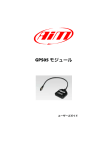
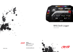
GPS05 Module
USER GUIDE
AiM Srl.
Via Cavalcanti, 8
20063 Cernusco S/N (MI)
Italia
Tel. (+39) 02.9290571
Fax (+39) 02.92118024
Made in Italy
www.aim-sportline.com
Thank you!
For choosing to purchase our GPS05 Module.
GPS05 Module
02
04
INTRODUCTION
06
GPS05 CONFIGURATION
08
CONNECTION TO AIM LOGGERS
10
GPS05 AND MXL
14
GPS05 AND EVO3 / ECU BRIDGE
16
GPS05 AND MYCHRON 4
26
USE GPS MANAGER SOFTWARE
36
USE RACESTUDIO2 ANALYSIS SOFTWARE
42
TEST ON THE TRACK WITH MXLPRO
54
DATA SHEET
GPS05 Module is the result of many hours of
research, development and consultation
with high level racing teams around the
world.
We wanted GPS05 Module not only to be
small, but also to be the most precise, powerful and reliable GPS receiver available
for the world market in Motor Racing today.
The simple installation and management
are features that are inherent in Aim GPS05
Module.
GPS05 Module will be your partner on the
track.
03
INTRODUCTION
What is GPS05 Module.
The data supplied
from GPS05.
GPS05 is a GPS receiver module that
can communicate with a display/data
logger through the CAN connection.
The GPS05 is able to store a maximum
of 50 tracks used to calculate lap and
split times.
GPS05 calculates, (10 times in a
second), the following information:
• Position
(latitude, longitude, altitude)
• Speed
• Longitudinal acceleration
• Latitudinal acceleration
The data that is stored for each track:
•
•
•
•
Track name
Track type
Lap beacon position
Possible split position
Also it supplies information
concerning:
• Lap times
• Split times
• Test duration
The data is used to:
• Identify the track
• Calculate travel times
• Calculate split times
04
This information is continuously transmitted to the logger via the CAN connection.
Which circuit types are
managed?
If the GPS05 library does
not include the track?
Closed circuits or point to point races,
like uphill races or rallies.
It can be easily added as explained in
this user manual.
05
CHAPTER 1
GPS05 MODULE CONFIGURATION
GPS05 MODULE
How to configure
GPS05 Module.
The GPS05 needs to be configured to identify the lap beacon position to record lap
times.
Calculate You can choose the lap beacon
position in two ways:
n Using AIM software GPS Manager
n Directly on the track
Using GPS Manager software and transmitting the information about the tracks to the
GPS05.
GPS05 will automatically recognise the
track at power on and will use the lap and
split positions and other important points
for the calculations.
Setting the position of the lap beacon directly from the track while driving on the
circuit.
06
This can be done only if GPS05 is connected
to one of our Aim loggers.
07
CHAPTER 2
CONNECTION TO AIM LOGGERS
GPS05 MODULE
Ho to connect GPS05 to Aim loggers.
Aim Loggers that support GPS05 do not need a special configuration: they automatically
recognise the GPS Module and start sampling and storing GPS data.
However, in case you want to show on your display the GPS speed, or to use the coordinates
for lap time, the system will need specific information. Below shows how to configure different
Aim devices.
Dash Logger
08
GPS05
GPS05
Data Logger
Display
09
CHAPTER 3
GPS05 AND MXL
GPS05 MODULE
GPS05 connected to MXL.
You can connect GPS05 to all MXL models ( Pro, Pista and Strada ).
Please, note that the firmware has to be at least 14.86.47.
n Connection to MXL Pista and Strada
The connection is direct: simply use the 5
pin connector in the back of the dash.
Direct connection connector
n Connection to MXL Pro05
In order to connect GPS05 to MXLpro,
please, use the proper CAN connector that
you find in the harness.
Pressing “<<” e “>>” you can view the
satellite signal status.
On the bottom of the display it will show:
Number of connected satellites
Satellite status
Available options are:
Search: Searching for satellites signal
Weak: GPS signal is weak
Good: Signal reception is ok
Buttons
10
N°Sat
Status Sat
11
CHAPTER 3
How to configure MXL when connected to GPS05.
The MXL needs information about speed
and lap time to manage GPS05.
Use the “System Configuration” section
of Aim RaceStudio2 software to update
these parameters.
n Speed
Your logger can get speed information
from the ECU, from wheel sensors or from
GPS.
Please, select “GPS Speed” (1) if you wish
to use this one as “reference speed”, that is
GPS05 MODULE
GPS05 AND MXL
to say as information for compute the predictive lap time, the distance from the starting point and as speed shown on the
display.
n Lap times calculated from GPS
position
MXL can calculate lap time from an optical
receiver or using the GPS signal.
In this last case track width must also be
selected. (2)
Configuring the lap beacon through MXL.
To update lap and split beacon on GPS05
Module follow this procedure:
• Ensure that the GPS Module is correctly
connected to MXL.
• Press “MENU” on MXL keyboard.
• The system shows a menu with backlight
or GPS options.
• Select “Set GPS beacon” using “>>/<<”
buttons.
• Press “OK”.
1
2
The MXL will then prompt to fix the lap beacon. Go to selected start/finish line and press
“OK”. Lap beacon is now saved.
1
2
Once the lap beacon is saved, if the system
is required to sample split times, the following page will appear: go to the selected
split point and press “OK”.
3
When configuration is over, the system
shows the main page and sampling can
now be done.
“GOOD TRK”, circled here below, confirms
that the system has recognised the track
and is ready to sample lap and split times.
4
To cancel the procedure switch off/on MXL.
n WARNING!
in case of weak satellite signal the system can ask for the procedure to be repeated. It is strongly recommended not
to fix lap/split times under bridges or
near any large obstacles.
12
13
CHAPTER 4
GPS05 AND EVO3 / ECU BRIDGE
GPS05 MODULE
GPS05 with EVO3 or ECU Bridge.
Use RaceStudio2 to configure EVO3 or ECU
Bridge.
Your system needs information about
speed (1) and lap time (2) to manage GPS05:
use the System Configuration section of
Aim RaceStudio2 software to fix these
points.
2
1
14
n Speed
n Lap times coming from the GPS position
Your logger can get speed information
from the ECU, from wheel sensors or from
GPS.
Please, select “GPS Speed” if you wish to
use this one as “reference speed”, that is to
say as information for compute the predictive lap time, the distance from the starting
point and as speed shown on the display.(1)
EVO3 can calculate lap times using an
optical signal or a GPS signal.
In this last case, GPS05 is to be enabled so
that it can provide the information and the
track width is to be defined as well.(2)
15
CHAPTER 5
GPS05 with MyChron4.
GPS05 AND MYCHRON4
GPS05 MODULE
If you wish to build a network with more peripherals use a Data Hub Expansion Module, as
shown here below.
The easiest way to connect GPS05 to MyChron4 is a straight connection through the 5 pin EXP
(expansion) connector on the back of the MyChron4.
To externally power the network refer to the scheme here below.
Connector for a direct connection
16
17
CHAPTER 5
MyChron4 at the power on.
GPS05 AND MYCHRON4
Configuring the lap beacon from MyChron4.
At power on, the logger shows firmware
versions of all the items of the network as
below.
Once the MyChron4 is connected to GPS05
and switched on, press “On/View” until
page “G.P.S. Data” appears.
MyChron4, eBox Gold
and GPS05 Module firmware versions.
This page will allow you to check if the
GPS05 is working correctly and if it is
receiving satellite signals.
It is also possible to fix lap beacon through
the keyboard; just cross the start/finish line
and press “OK”.
18
GPS05 MODULE
19
CHAPTER 5
GPS05 AND MYCHRON4
GPS05 MODULE
Selecting the track from MyChron4.
n WARNING!
To use GPS05 for lap times calculation,
just set “Lap type” in MyChron4 configuration.
When selecting “GPS Lap timer” - this lap
timing mode becomes the default.
When selecting optical/magnetic – this
lap timing mode becomes the default.
GPS05 can store up to 50 track
configurations with a maximum of 5 splits
for each track.
The track is automatically recognised
within a 5 km radius.
MyChron4 informs the user that more
tracks are available in a 5 km radius.
Press “>>” and the list of available tracks
appears:
The message “Track Ok!” shown central on
the display means that the track has been
recognised and the system can sample lap
and, if required to, split times.
If GPS05 Module detects more than one
track in a 5 km radius, MyChron4 display
shows this page:
The desired track can be manually selected
by pressing “OK”.
If no choice is made the logger selects a
track according to the situation:
If GPS Lap Timer is enabled in the
MyChron4 menu, and the GPS05 is disconnected, then the lap times calculations are
switched automatically to
optical/magnetic receiver mode.
n In case there are two physically different tracks
just run a complete track lap to let GPS
detect the track; sampled data can be
considered reliable from the second
complete track lap.
n In case there are two or more settings
of the same track
the GPS05 Module selects the last one
stored.
At the end of the session you can check the
selection your GPS05 made for you just by
entering available tracks page: press “>>”.
20
21
CHAPTER 5
GPS05 AND MYCHRON4
GPS05 MODULE
What MyChron4 displays during the race.
Pressing“VIEW”, MyChron4 display shows,
GPS speed with the related unit of measure
(kmh/mph) under the RPM graph bar.
By pressing “VIEW” again the GPS signal
level appears and will show:
n Number of connected satellites
n Status GPS
Possible options:
Search:
Bad:
Weak:
Good:
searching for GPS signal
bad reception
weak reception
good reception
n GPS Speed
22
23
CHAPTER 5
GPS05 AND MYCHRON4
GPS05 MODULE
Troubleshooting
If the display shows:
If the display shows:
n "Bad Setting, please Restart"
n "GPS OFF"
the configuration procedure did not
succeed and should be repeated.
The GPS firmware needs to be upgraded.
Press “VIEW” and repeat the procedure.
If the display shows:
If the display shows:
n "GPS LapTimer Initializing"
n "GPS FW must be Upgraded"
GPS Lap Timer is starting; just wait for a few
moments for it to update.
The GPS firmware needs to be upgraded.
If the display shows:
n "GPS Tracks Memory Full"
There is already data for 50 tracks stored.
Use GPS Manager software to delete less
important data.
24
25
CHAPTER 6
Use GPS Manager
software.
GPSManager is the software that allows you
to update, modify, read and write on your
GPS05 lap and split beacons of the track
you are going to race on.
1
USE GPS MANAGER SOFTWARE
2
3
4
GPS05 MODULE
5
8
GPSManager, when ther is no logger
connected to your PC, shows the image
you can see here.
On your left you have the list of the tracks
in your PC, organized depending upon the
country in which they are.
7
Track shape, when available, and
information about the typology of the track
( for kart, cars, bikes) are also shown.
On your right you have the image of the
track in which you have the mouse.
1
Track management command
2
Selection window for dynamic filters
3
Track type: car, bike, karts
4
Track data manager
5
Track shape, with starting line
and split points position
6
Small track shape
7
Track selection
8
Open/Close Country track data
6
26
27
CHAPTER 6
USE GPS MANAGER SOFTWARE
GPS05 MODULE
Filters in track data base management.
The list of the tracks that you have in your
PC can be very long and is constantly
updated by our technicians. It can be useful
to filter part of them, in order to better
manage the information.
Dynamic filters remain active only till when
you close GPS Manager.
You can use this filter introducing the name
of a particular country and vehicle in the
small window at the top left of the page.
We can have two different filters, that we
call “Dynamic” (2) or “Static” (1).
If, for example, you write KART US, you will
see only the kart tracks in the United States.
2
Dynamic filters are fast to use, give an
immediate feedback and are not saved
when you close the software.
Static filters are used when you have to define the geographical environment (the
country) in which you normally use your
GPS and are saved also when you close the
program.
1
Static filters are activated by pushing
pushbutton “Filter” (1): you can select
countries, type of vehicle and type of track
that you wish, using the window here
shown.
Please, notice that the lists whow countries,
vehicles and type of circuits that appear at
least once in your database: if, for example,
you delete all the tracks in Germany, this
country will not appear in the list.
28
29
CHAPTER 6
USE GPS MANAGER SOFTWARE
GPS05 MODULE
How to add a new track to the PC database.
To add a track to your track list, proceed this
way:
1
It is now possible to select the file “.GPK”,
containing the coordinates of all the points
of your test.
1) Press “New”
2) Please, insert the track name in the
window
2
The shape of the track appears, splitted in
different laps of the test. It is possible to
scroll through the different laps, to zoom,
to rotate the drawing.
3) Please, fill the fields: country, type of
track (closed track, Oval, point to point),
type of surface ( asphalt, dirt, ice, water).
Finally, please select the type of vehicle that
generally runs in the circuit:
Car, Bike or Kart.
3
After having selected the desired lap, push
“OK” for saving the image of that lap.
That image will be used as a reference
shape for the future.
Finish line coordinates are read from the
“.GPPK” file but can be modified as desired
in one of the following ways:
Define the coordinate by hand (1)
If you have already produced a test file with
GPS data (“.GPK” file, that you get downloading data from your logger using Aim
software RaceStudio2), you can define the
track shape pushing the pushbutton
“Load Shape”.
Position the cursor on the desider point
of the track and click the pushbutton
“Cursor Pos” (2)
In case of a Point to Point track, it is obviously useful to define the coordinates of the
starting and finish line.
Push “OK” for saving the configuration.
30
1
2
31
CHAPTER 6
USE GPS MANAGER SOFTWARE
GPS05 MODULE
How to modify track data in the PC database.
How to read, write and delete tracks form GPS05.
Click on the pushbutton (4) that appears at
the side of the track shape icon: the
following window will appear. Please,
modify data in accordance to your
necessities.
Please connect your system, composed by
a Master Unit ( MXL, EVO3, MyChron 4 with
Data Key, Smartycam) and GPS05 to your
PC through USB connection.
GPS Manager will automatically show you,
on the right side of the display, the list of
the tracks inside GPS05.
32
4
As you can notice, the information available
are a subset of what you have in the PC
database: only the track name and coordinates.
The track shape is transmitted only to
SmartyCam.
33
CHAPTER 6
USE GPS MANAGER SOFTWARE
GPS05 MODULE
To delete Tracks data from GPS05
To delete data from GPS05 simply select the
track(s) in the right panel and push
“Erase Selected”.
To change track name in GPS05
If you wish to change the name of the track
in GPS05 without or before moving it to
your PC ( for example, when you have got
the beacon position directly on your
system), simply double click on the name
of the track, change the name and close the
panel.
1
2
In order to transmit data to GPS05
In order to receive data from GPS05
Select the tracks to transmit, by clicking on
the left square or double clicking on the
track name.
Select the tracks to receive, by clicking on
the left square or double clicking on the
track name.
Move the track toward the right panel or
push the Arrow “►” (1).
Move the toward the left panel or push the
Arrow “◄” (2).
The track information are moved toward
GPS05.
The track information are moved toward
the PC database.
34
GPS05 will be automatically upgraded.
35
CHAPTER 7
USE RACE STUDIO ANALISI SOFTWARE
GPS05 MODULE
Data Analysis using GPS05 information.
After the test you can download your data
to the PC for a deep analysis thank to the
professional software Aim RaceStudio
Analysis.
Please, select “View>>GPS Data” for looking at the trajectory of the vehicle during
its test.
The data obtained by GPS are:
GPS Speed
Speed obtained from GPS signals
GPS Nsat
Number of satellites seen by the GPS receiver. In order to have a good quality signal,
the receiver is supposed to see at least 7 satellites.
GPS LatAcc
lateral acceleration toward the direction of
the movement.
GPS LonAcc
Longitude acceleration in the direction of
the movement
36
GPS Slope
slope of the movement.
GPS Heading
direction of the vehicle in degrees ( -/+ 180
toward the North).
GPS Gyro
vehicle yaw in degrees/sec.
GPS Pacc
Precision Accuracy gives the precision correlated with the calculated position of the
vehicle.
It is considered good when is about 2 mt.
37
CHAPTER 7
In the picture you can see four different trajectories in the same point of the track, in
different colours in dependence upon the
speed of the vehicle.
38
You can zoom the image in order to have a
good resolution.
USE RACE STUDIO ANALISI SOFTWARE
GPS05 MODULE
You can also export the track drawing into
a ".kml" file in order to see it in overlay in
Google Earth.
39
CHAPTER 7
USE RACE STUDIO ANALISI SOFTWARE
How to use GPS05 data to calculate lap times
after the test.
This view appears:
If the system is not correctly configured a
test session can miss the correct lap times.
On the left are four possible division criteria
based on the lap coordinates.
GPS05 MODULE
1
Your PC track database
On the right is your test with no laps.
2
Cursor position on the track
Each lap time can be calculated, assuming
of course that GPS data is correct.
To re-calculate lap times:
Select “GPS Lap Insert” in Lap Manager
view.
3
Manually filled in coordinates
These coordinates can come from:
4
Another test performed on the same track.
In this case the source test name is needed
1
1
2
3
4
Select the option you prefer: at the end of this setting lap times are easily re-calculated
40
41
CHAPTER 8
TEST ON THE TRACK WITH MXLPRO
GPS05 MODULE
Mxl Pro
Oversteering and understeering analysis.
To hold this test, we have been using the
following sensors:
- GPS
- 4 shock potentiometers
- Steering angle potentiometer
- Front and rear brake pressure
potentiometer
- Longitudinal accelerometer
- Lateral accelerometer
- Gyro
- 4 speed sensors
- All channels acquired from MBE 992
ECU connected in CAN line
But a brief explanation is required:
let’s take, for example, the lateral acceleration value as shown in the diagram below.
1
on the other side, on oversteering vehicle,
the value of the projection on the normal
Lateral acceleration vector trajectory calculated through the on board lateral accelerometer (identified as “B”), is lower than
the GPS-calculated one,
2
Similarly, in case of understeering, we obtain a C related longitudinal acceleration
component called C’, due to its projection
on the normal trajectory, that adds itself*
vectoriarly to the normal lateral accelaration related to B’ trajectory.
3
Analysis
One of the troubles reported in on-track
data analysis is to understand with a good
approximation, the behaviour of the vehicle when the driver pulls it to the limit,
especially in understeering and oversteering situations.
We remind you that oversteering is caused
by loss of grip of the rear axle (opposite
steering is needed), while understeering is
caused by loss of heading of the steering
axle (the car’s trend is to “go straight ”).
A valuable instrument for analysing the vehicle reaction, is comparing GPS values and
on-board dedicated sensor values.
42
Let’s identify with “A” the GPS_LatAcc vector module, calculated through GPS antenna trajectory.
We’ll call “B” the Lateral Acceleration vector
module, obtained by on-board lateral
accelerometer values.
B’ is also affected by the Longitudinal acceleration vector projection “C” on the normal trajectory as shown in the picture
below.
With vehicle completely deviated compared to normal trajectory, the result value
would be a “B” Lateral Acceleration equal
to zero.
Now, let’s identify a simple match channel
called Diff_LatAcc by using the formula:
Diff_LatAcc = GPS_LatAcc - LatAcc
With a neutral car (not affected by
understeering or oversteering condition)
and with constant speed and cornering
radius, A and B vectors are equal.
43
CHAPTER 8
We can extend this reasoning also to the
gyro.
Let’s take for example gyro e GPS_gyro
channels values.
This is because the GPS_gyro channel indicates the vehicle’s yawrate as tangent of
covered trajectory, while the gyroscope
sensor measures vehicle’s cornering.
If the vehicle is in a oversteering condition,
inertial sensor value will be more than
gps_gyro because the vehicle would had a
wider yaw angle than trajectory related
one. Let’s mark right curves as positive and
left corners are as negative.
Let’s create a second math channel called
Diff_gyro, defined by the formula:
For all right corners in oversteering condition we obtain
gyro>GPS_gyro
Diff_gyro=GPS_gyro - Gyro
In case of left corners, with parity between
cornering range and yaw angle with oversteering vehicle, we’ll obtain
GPS_gyro > gyro
TEST ON THE TRACK WITH MXLPRO
GPS05 MODULE
To define these conditions, it is necessary
to use absolute values:
Diff_Gyro Abs = abs(GPS_Gyro)-abs
(gyro)
This way, the absolute value will be considered, no matter what their sign is.
The difference channel obtained through
absolut gyroscope values will be named as
Diff_Gyro Abs.
In the meanwhile, we have to create the
Diff_LatAcc Abs channel.
The correct syntactic string to be inserted as
math channel in RaceStudio 2 software is:
At this point, we can say that:
So the channel
1 Diff_gyro
>0
2 Diff_gyro
<0
understeer
Diff_gyro = GPS_gyro - gyro
Diff_LatAcc Abs = abs(GPS_LatAcc)
- abs(Acc_1)
2 Diff_gyro cond < 0 oversteer
oversteer
3 Diff_LatAcc > 0
oversteer
4 Diff_LatAcc < 0
understeer
1 Diff_gyro cond > 0 understeer
To obtain the same oversteering indication,
the parameters have to be inverted and defined as:
Once the channels have been defined, the
behaviour of the vehicle can be summarized
in this way:
3 Diff_LatAcc
>0
understeer
4 Diff_LatAcc
<0
oversteer
Diff_gyro = gyro-GPS_gyro
But further explanation is needed.
44
45
CHAPTER 8
Now, let’s analyze these two math channels
values.
TEST ON THE TRACK WITH MXLPRO
GPS05 MODULE
Thanks to GPS trajectories software viewer, it is possible to obtain a chromatic scale of
Diff_gyro Abs and Diff_LatAcc Abs values with related variation on the track map.
B
C
D
E
F
G
A
We can immediately observe that both
channels:
As said before, blue zones indicate
oversteer while red ones are understeer.
This behaviour is less noticeable in corners
A and B.
Black Diff_gyro Abs,
Red Diff_LatAcc abs
It’s easy to verify how the vehicle oversteered while entering some corners (marked
as C, D, E, F, G blue points).
Please note the change between
oversteering and understeering in corners
B, E and G.
Are in phase , giving us a double check of
what said before.
46
47
CHAPTER 8
This is evidenced through the analysis of
Diff_Gyro Abs channel also.
TEST ON THE TRACK WITH MXLPRO
GPS05 MODULE
Now, let’s analyze a specific part of the
track.
€
D
DIRECTION
Also in this case, oversteering condition is
evidenced in blue, while the understeering
condition is evidenced in red.
48
It’s clearly evedenced how the vehicle
reaches point D while braking after the
straight line and understeer before
entering the left corner in oversteering
condition.
49
CHAPTER 8
GPS05 MODULE
By analyzing driver’s behaviour in this corner, we can notice that the car is neutral because of
driver applying brake and throttle at the same time:
This is also evidenced by “Diff_Gyro Abs”
channel.
D’
TEST ON THE TRACK WITH MXLPRO
D
but it becomes undesteering in throttleopening phase as evidenced.
The steer channel viewed at D’’ point,
shows that the driver had to strongly deal
with the steering wheel to keep the vehicle
in the best trajectory.
50
D”
51
CHAPTER 8
The strong oversteering behaviour at the entrance of the corner and the understeer while exiting, was caused by the wreck of front left shock absorber.
TEST ON THE TRACK WITH MXLPRO
GPS05 MODULE
As clearly shown in shock speed histogram, the “A” shock loss completely efficiency, causing
the shock itself to work without any absorbtion.
A
D”
B
This shock failure caused the vehicle to
loose grip.
Note how the rear right shock “B” suffers
mainly this condition.
With parity of compression and extension
settings at high and low speeds compared
to rear left, the rear right can’t absorb the
tyre shaking.
52
While reading shock speed histograms,
don’t forget that “X Axis” is automatically
software-scaled.
The diagram low scale for the rear left shock
is 25%, while is 20% for the rear right.
With scale parity, the rear right diagram
should be compressed.
53
CHAPTER 09
GPS05 DATA SHEET
GPS05 MODULE
GPS05 Module
n Vehicle position
n Track map
n CAN output (all parameters)
n No calibration required
n Cable length: 2 mt
n Nylon box
n Colour black
n Dimension mm. 64 x 53 x 20
n Weight: 60.5 g
Our web site aim-sportline.com is constantly
updated.
n 6 Channel
We try to share with you our experiences
about our products and how to use them
in the tracks all over the world.
n GPS speed
n Lateral acceleration
n Linear acceleration
n GPS heading
n GPS yaw rate
n Satellite number
54
Please, constantly check it and download
the last versions of the firmware of your
products.
55