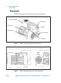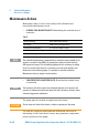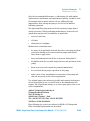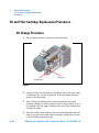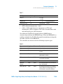
1
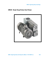
MS40+ Single Stage Rotary Vane Pumps Models: 949-9225, 949-9240, 949-9241 Manuale di Istruzioni Bedienungshandbuch Notice de Mode D’Emploi User Manual 87-901-008-01 (E) 05/2013 Warranty Notices © Agilent Technologies, Inc. 2011 No part of this manual may be reproduced in any form or by any means (including electronic storage and retrieval or translation into a foreign language) without prior agreement and written consent from Agilent Technologies, Inc. as governed by United States and international copyright laws. Manual Part Number Publication Number: 87-901-008-01 (E) Edition Edition 05/2013 Printed in ITALY Agilent Technologies Italia S.p.A. Vacuum Products Division Via F.lli Varian, 54 10040 Leinì (TO) ITALY The material contained in this document is provided “as is,” and is subject to being changed, without notice, in future editions. Further, to the maximum extent permitted by applicable law, Agilent disclaims all warranties, either express or implied, with regard to this manual and any information contained herein, including but not limited to the implied warranties of merchantability and fitness for a particular purpose. Agilent shall not be liable for errors or for incidental or consequential damages in connection with the furnishing, use, or performance of this document or of any information contained herein. Should Agilent and the user have a separate written agreement with warranty terms covering the material in this document that conflict with these terms, the warranty terms in the separate agreement shall control. Technology Licenses The hardware and/or software described in this document are furnished under a license and may be used or copied only in accordance with the terms of such license. Restricted Rights Legend If software is for use in the performance of a U.S. Government prime contract or subcontract, Software is delivered and licensed as “Commercial computer software” as defined in DFAR 252.227-7014 (June 1995), or as a “commercial item” as defined in FAR 2.101(a) or as “Restricted computer software” as defined in FAR 52.227-19 (June 1987) or any equivalent agency regulation or contract clause. Use, duplication or disclosure of Software is subject to Agilent Technologies’ standard commercial license terms, and nonDOD Departments and Agencies of the U.S. Government will receive no greater than Restricted Rights as defined in FAR 52.227-19(c)(1-2) (June 1987). U.S. Government users will receive no greater than Limited Rights as defined in FAR 52.227-14 (June 1987) or DFAR 252.227-7015 (b)(2) (November 1995), as applicable in any technical data. Trademarks Windows and MS Windows are U.S. registered trademarks of Microsoft Corporation. Safety Notices CAUTION A CAUTION notice denotes a hazard. It calls attention to an operating procedure, practice, or the like that, if not correctly performed or adhered to, could result in damage to the product or loss of important data. Do not proceed beyond a CAUTION notice until the indicated conditions are fully understood and met. WARNING A WARNING notice denotes a hazard. It calls attention to an operating procedure, practice, or the like that, if not correctly performed or adhered to, could result in personal injury or death. Do not proceed beyond a WARNING notice until the indicated conditions are fully understood and met. MS40+ Single Stage Rotary Vane Pumps User Manual / 87-901-008-01 (E) MS40+ Single Stage Rotary Vane Pumps MS40+ Single Stage Rotary Vane Pumps MS40+ Single Stage Rotary Vane Pumps User Manual / 87-901-008-01 (E) 3/90 MS40+ Single Stage Rotary Vane Pumps 4/90 MS40+ Single Stage Rotary Vane Pumps User Manual / 87-901-008-01 (E) Contents Contents 1 Istruzioni per l’uso 9 Informazioni Generali 10 Immagazzinamento 11 Preparazione per l’installazione 11 Installazione 13 Uso 15 Manutenzione 15 Smaltimento 2 18 Gebrauchsanleitung 19 Allgemeine Hinweise Lagerung 20 21 Vor der Installation 21 Installation 23 Gebrauch 25 Wartung 25 Entsorgung 27 3 Mode d’emploi 29 Indications générales 30 Emmagasinage 31 MS40+ Single Stage Rotary Vane Pumps User Manual / 87-901-008-01 (E) 5/90 Contents Preparation pour l‘installation 31 Installation 33 Utilisation 35 4 Maintenance 35 Mise au rebut 37 Instructions for Use 39 General Information 40 Storage 41 Preparation for Installation 41 Installation 43 Use 45 Maintenance Disposal 5 45 47 Technical Information Section I 49 51 Technical Description 51 Vacuum Seals 52 Anti-Suckback Device 52 Technical Data 53 Safety Precautions 55 Transport and Installation Section II 6/90 55 57 MS40+ Single Stage Rotary Vane Pumps User Manual / 87-901-008-01 (E) Contents Connection to the Electric Supply 57 Connections to the Inlet and Exhaust Flanges 57 Starting and Running the Pump 59 Stopping the Pump 60 Safety Rules60 Warning Notes 61 Caution Notes 63 Maintenance Actions 64 Oil and Filter Cartridge Replacement Procedures 66 Lubricants 68 Pump Electronic Controller 71 RS 232/RS 485 Communication Description 75 Accessories 83 MS40+ Single Stage Rotary Vane Pumps User Manual / 87-901-008-01 (E) 7/90 Contents 8/90 MS40+ Single Stage Rotary Vane Pumps User Manual / 87-901-008-01 (E) MS40+ Single Stage Rotary Vane Pumps User Manual 1 Istruzioni per l’uso Informazioni Generali 10 Immagazzinamento 11 Preparazione per l’installazione 11 Installazione 13 Uso 15 Manutenzione 15 Smaltimento 18 Traduzione delle istruzioni originali 9/90 1 Istruzioni per l’uso Informazioni Generali Informazioni Generali Questa apparecchiatura è destinata ad uso professionale. L'utilizzatore deve leggere attentamente il presente manuale di istruzioni ed ogni altra informazione addizionale fornita dalla Agilent prima dell'utilizzo dell'apparecchiatura. La Agilent si ritiene sollevata da eventuali responsabilità dovute all'inosser-vanza totale o parziale delle istruzioni, ad uso improprio da parte di personale non addestrato, ad in-terventi non autorizzati o ad uso contrario alle normative nazionali specifiche. Le MS40+ Single Stage Rotary Vane Pumps sono delle pompe rotative monostadio a palette, a tenuta in bagno d'olio, azionate da motore elettrico trifase. Queste pompe da alto vuoto sono adatte al pompaggio di gas non corrosivi. Nei paragrafi seguenti sono riportate tutte le informazioni necessarie a garantire la sicurezza dell'operatore durante l'utilizzo dell'apparecchiatura. Informazioni dettagliate sono fornite nell'appendice “Technical Information”. Questo manuale utilizza le seguenti convenzioni: AVVERTENZA! I messaggi di avvertenza attirano l’attenzione dell’operatore su una procedura o una pratica specifica che, se non eseguita in modo corretto, potrebbe provocare gravi lesioni personali. ATTENZIONE! I messaggi di attenzione sono visualizzati prima di procedure che, se non osservate, potrebbero causare danni all’apparecchiatura. NOTA 10/90 Le note contengono informazioni importanti estrapolate dal testo. MS40+ Single Stage Rotary Vane Pumps User Manual / 87-901-008-01 (E) 1 Istruzioni per l’uso Immagazzinamento Immagazzinamento Durante il trasporto e l'immagazzinamento delle pompe non devono essere superate le seguenti condizioni ambientali: temperatura: da -20 °C a 70 °C umidità relativa: 0 – 95 % (non condensante) Preparazione per l’installazione La pompa viene fornita in un imballo protettivo specia-le; se si presentano segni di danni, che potrebbero essersi verificati durante il trasporto, contattare l'ufficio vendite locale. Il peso dell’imballo, comprensivo della pompa, è, al massimo, di circa 35 Kg. Durante l'operazione di disimballaggio, prestare particolare attenzione a non lasciar cadere la pompa e a non sottoporla ad urti o vibrazioni. Non disperdere l'imballo nell'ambiente. Il materiale è completamente riciclabile e risponde alla direttiva CEE 85/399 per la tutela dell'ambiente. NOTA La pompa non può essere danneggiata rimanendo semplicemente esposta all'atmosfera. Si consiglia comunque di mantenerla chiusa fino al momento dell'installazione sul sistema onde evitare eventuale inquinamento da polvere. MS40+ Single Stage Rotary Vane Pumps User Manual / 87-901-008-01 (E) 11/90 1 Istruzioni per l’uso Preparazione per l’installazione NOTA La pompa è fornita con alcuni accessori standard: 1 connettore "D" a 9 contatti per I/O (femmina) (escluso il modello 949-9241) 1 connettore "D" a 9 contatti per RS232 (maschio) (escluso il modello 949-9241) Molla di ritenuta per presa IEC320 Figura 1 12/90 MS40+ Single Stage Rotary Vane Pumps User Manual / 87-901-008-01 (E) 1 Istruzioni per l’uso Installazione Installazione Non installare e/o utilizzare la pompa in ambienti esposti ad agenti atmosferici (pioggia, gelo, neve), polveri, gas aggressivi, in ambienti esplosivi o con elevato rischio di incendio. Durante il funzionamento è necessario che siano rispettate le seguenti condizioni ambientali: temperatura: da +12 °C a +40 °C umidità relativa: 0 – 95 % (non condensante) valore di IP. ATTENZIONE! Prima di avviare la pompa, verificare il livello dell’olio. AVVERTENZA! Togliere i tappi di protezione posti sulle flange di aspirazione e scarico prima di ogni successiva operazione. L’aria contenuta all’interno della pompa, in caso di accensione involontaria, può proiettarli violentemente contro l’operatore e ferirlo. AVVERTENZA! Durante l'installazione, prestare la massima attenzione che la flangia di aspirazione sia collegata alla camera da evacuare e che la flangia di scarico non sia tappata (vedere la figura seguente). La pompa non deve essere usata come compressore. La massima pressione interna al contenitore dell'olio non deve superare 1,5 bar (abs). L'inosservanza di queste precauzioni può causare danni alla macchina ed all'operatore. MS40+ Single Stage Rotary Vane Pumps User Manual / 87-901-008-01 (E) 13/90 1 Istruzioni per l’uso Installazione Flangia di aspirazione Flangia di scarico Figura 2 ATTENZIONE! Controllare che la tensione di alimentazione corrispon-da al campo di valori indicati sulla targhetta del controller. Collegare la pompa all’alimentazione. 14/90 MS40+ Single Stage Rotary Vane Pumps User Manual / 87-901-008-01 (E) 1 Istruzioni per l’uso Uso Uso L'accensione della pompa non richiede particolari ma-novre; è sufficiente collegarla all’alimentazione elettrica agendo sull’interruttore bipolare. AVVERTENZA! La pompa è progettata per operare con fluidi neutri o non corrosivi. È assolutamente vietato l'impiego con sostanze potenzialmente esplosive o infiammabili. Manutenzione Il personale addetto alla condotta ed alla manutenzione della pompa deve essere ben addestrato e deve avere un'approfondita conoscenza delle norme antinfortunistiche. AVVERTENZA! Le alte tensioni possono causare morte al contatto. Operare sempre con la massima cautela e secondo le norme antinfortunistiche in vigore. MS40+ Single Stage Rotary Vane Pumps User Manual / 87-901-008-01 (E) 15/90 1 Istruzioni per l’uso Manutenzione AVVERTENZA! Quando la macchina è alimentata prestare attenzione per la presenza di parti in movimento e di alta tensione. AVVERTENZA! Nel caso si debba procedere ad operazioni di manutenzione della pompa al termine di un periodo di esercizio, è necessario lasciarla raffreddare, poichè la temperatura esterna può superare i 60 °C. AVVERTENZA! Escludere sempre l'alimentazione della pompa prima di compiere operazioni di manutenzione. Apporre specifici cartelli di avvertenza: APPARECCHIATURA IN MANUTENZIONE - NON INSERIRE L'ALIMENTAZIONE, in corrispondenza dell'interruttore di alimentazione. Al termine ripristinare i dispositivi di sicurezza. AVVERTENZA! Non effettuare la sostituzione dell’olio subito dopo l’arresto della macchina, in quanto la temperatura dello stesso può essere elevata. 16/90 MS40+ Single Stage Rotary Vane Pumps User Manual / 87-901-008-01 (E) 1 Istruzioni per l’uso Manutenzione NOTA Prima di rispedire al costruttore una pompa per ri-parazioni è indispensabile compilare e far pervenire al locale ufficio vendite la scheda "Health and Safety Certification" allegata al presente manuale di istruzioni. Copia della stessa deve essere inserita nell'imballo della pompa prima della spedizione. Qualora una pompa dovesse essere rottamata, procedere alla sua eliminazione nel rispetto delle normative nazionali specifiche. MS40+ Single Stage Rotary Vane Pumps User Manual / 87-901-008-01 (E) 17/90 1 Istruzioni per l’uso Smaltimento Smaltimento Significato del logo "WEEE" presente sulle etichette. Il simbolo qui sotto riportato è applicato in ottemperanza alla direttiva CE denominata "WEEE". Questo simbolo (valido solo per i paesi della Comunità Europea) indica che il prodotto sul quale è applicato, NON deve essere smaltito insieme ai comuni rifiuti domestici o industriali, ma deve essere avviato ad un sistema di raccolta differenziata. Si invita pertanto l'utente finale a contattare il fornitore del dispositivo, sia esso la casa madre o un rivenditore, per avviare il processo di raccolta e smaltimento, dopo opportuna verifica dei termini e condizioni contrattuali di vendita. 18/90 MS40+ Single Stage Rotary Vane Pumps User Manual / 87-901-008-01 (E) MS40+ Single Stage Rotary Vane Pumps User Manual 2 Gebrauchsanleitung Allgemeine Hinweise 20 Lagerung 21 Vor der Installation 21 Installation 23 Gebrauch 25 Wartung 25 Entsorgung 27 Übersetzung der Originalanleitungen 19/90 2 Gebrauchsanleitung Allgemeine Hinweise Allgemeine Hinweise Dieses Gerät ist für den professionellen Gebrauch bestimmt. Vor dem Gebrauch soll der Benutzer dieses Handbuch sowie alle weiteren von Agilent mitgelieferten Zusatzinformationen genau lesen. Bei vollständiger bzw. teilweiser Nichtbeachtung der enthaltenen Hinweise, unsachgemäßem Gebrauch durch ungeschultes Personal, nicht autorisierten Eingriffen und Benutzung unter Missachtung der nationalen Bestimmungen übernimmt Firma Agilent keinerlei Haftung. Die Pumpen MS40+ Single Stage Rotary Vane Pumps sind dichte ölbadgeschmierte einstufige Flügelzellenpumpen, die von einem Dreiphasenstrommotor betätigt werden. Diese Hochvakuumpumpen eignen sich für das Pumpen von nicht korrosiven Gasen. In den folgenden Abschnitten sind alle erforderlichen Informationen für die Sicherheit des Bedieners bei der Verwendung des Geräts aufgeführt. Detaillierte technische Informationen sind im Anhang "Technical Information" enthalten. In dieser Gebrauchsanleitung werden Sicherheitshinweise folgendermaßen hervorgehoben: WARNUNG! Diese Warnung weist auf gefährliche Ar-beitsschritte hin, die bei unsachgemäßer Durchfüh-rung das Risiko von Personenschäden bergen. VORSICHT! Diese Warnung weist auf Arbeitsschritte hin, die das Risiko von Schäden am Gerät bergen. HINWEIS 20/90 Die Hinweise enthalten wichtige Informationen, die aus dem Text hervorgehoben werden. MS40+ Single Stage Rotary Vane Pumps User Manual / 87-901-008-01 (E) 2 Gebrauchsanleitung Lagerung Lagerung Während des Transports und der Lagerung der Pumpen sollen die folgenden Umgebungsbedingungen gegeben sein: Temperatur: -20 °C bis +70 °C Relative Feuchtigkeit: 0 – 95 % (niederschlagsfrei) Vor der Installation Die Pumpe wird in einer speziellen Schutzverpackung geliefert. Eventuelle Transportschäden sind der zustän-digen örtlichen Verkaufsstelle zu melden. Das Verpackungsgewicht beträgt, einschließlich der Pumpe, maximal 36 kg. Beim Auspacken ist darauf zu achten, dass die Pumpe nicht fallengelassen oder Stößen oder Vibrationen aus-gesetzt wird. Das Verpackungsmaterial ist ordnungsgemäß zu ent-sorgen. Es ist vollständig recyclebar und entspricht der EG-Richtlinie 85/399 für den Umweltschutz. HINWEIS Die Pumpe kann, wenn sie einfach der Atmosphäre ausgesetzt ist, nicht beschädigt werden. Sie sollte jedoch bis zur Installation an der Anlage geschlossen bleiben, um Verunreinigungen durch Staub zu vermeiden. MS40+ Single Stage Rotary Vane Pumps User Manual / 87-901-008-01 (E) 21/90 2 Gebrauchsanleitung Vor der Installation HINWEIS Die Pumpe wird mit einigen Standardzubehörteilen geliefert: 1 9-Stift-Stecker "D" für I/O (Steckbuchse) (mit Ausnahme der 949-9241-model) 1 9-Stift-Stecker "D" für RS232 (Stecker) (mit Ausnahme der 949-9241-model) Rückhaltefeder für Anschluss IEC320 Abbildung 1 22/90 MS40+ Single Stage Rotary Vane Pumps User Manual / 87-901-008-01 (E) 2 Gebrauchsanleitung Installation Installation Die Pumpe darf nicht in Umgebungen installiert und/oder benutzt werden, die ungeschützt vor Witterungsbedingungen (Regen, Frost, Schnee), Staub und aggressiven Gasen sind und in denen Explosionsoder erhöhte Brandgefahr besteht. Während des Betriebs sollen die folgenden Umgebungsbedingungen gegeben sein: VORSICHT! Temperatur: +12 °C bis +40 °C Relative Feuchtigkeit: 0 – 95 % (niederschlagsfrei) IP Wert. Vor Inbetriebnahme der Pumpe muss der Ölstand kontrolliert werden. WARNUNG! Vor Aufnahme jeglicher Arbeiten sind die Schutzkappen an den Saug- und Druckflanschen zu entfernen. Die im Pumpeninnern enthaltene Luft könnte diese bei unbeabsichtigter Einschaltung gegen den Bediener schleudern. WARNUNG! Bei der Installation ist unbedingt darauf zu achten, dass der Saugflansch an die zu entleerende Kammer ange-schlossen ist und der Ablassflansch nicht verschlossen ist (siehe nachstehende Abbildung). Die Pumpe darf nicht als Verdichter verwendet werden. Der Druck im Ölbehälter darf nicht größer als 1,5 bar (abs) sein. Bei Nichtbeachtung dieser Anweisungen besteht Schadensgefahr für das Gerät und die Bedienperson. MS40+ Single Stage Rotary Vane Pumps User Manual / 87-901-008-01 (E) 23/90 2 Gebrauchsanleitung Installation Saugflansch Ablassflansch Abbildung 2 VORSICHT! Vergewissern Sie sich, dass die Versorgungsspannung mit dem Wertbereich auf dem Typenschild des Kontrollers übereinstimmt. Die Pumpe an das Versorgungsnetz anschließen. 24/90 MS40+ Single Stage Rotary Vane Pumps User Manual / 87-901-008-01 (E) 2 Gebrauchsanleitung Gebrauch Gebrauch Die Einschaltung der Pumpe erfordert keine speziellen Schritte, sie braucht nur durch Betätigung des zweipoligen Schalters an den Strom angeschlossen zu werden. WARNUNG! Die Pumpe ist für den Betrieb mit neutralen und nicht korrosiven Fluiden konzipiert. Der Einsatz mit potentiell explosions- oder feuergefährlichen Substanzen ist streng verboten. Wartung Das für den Betrieb und die Wartung zuständige Personal soll geschult sein und über eine solide Kenntnis der Unfallschutzvorschriften verfügen. WARNUNG! Hochspannungen können bei Kontakt tödliche Folgen haben. Es ist stets mit größter Vorsicht und gemäß den geltenden Unfallschutzvorschriften vorzugehen. WARNUNG! Bei eingeschaltetem Gerät ist auf Bewegungs- und Hochspannungsteile zu achten. MS40+ Single Stage Rotary Vane Pumps User Manual / 87-901-008-01 (E) 25/90 2 Gebrauchsanleitung Wartung WARNUNG! Falls die Pumpe im Anschluß an den Betrieb gewartet werden soll, ist abzuwarten, bis sie abgekühlt ist, da ihre Oberfläche eine Temperatur von 60 °C überschreiten kann. WARNUNG! Vor Wartungsarbeiten ist die Pumpe stets energiefrei zu schalten. Am Netzschalter sind spezielle Warnschilder “INSTANDHALTUNG AM GERÄT – NICHT EINSCHALTEN” anzubringen. Nach Abschluss der Arbeiten sind die Sicherheitseinrichtungen wieder zu aktivieren. WARNUNG! Keine Ölwechsel unmittelbar nach Stillsetzung des Gerätes vornehmen, da die Öltemperatur sehr hoch sein kann. HINWEIS Bevor dem Hersteller eine Pumpe zur Reparatur zurückgesandt wird, ist das Formular “Sicherheit und Gesundheit” in der Anlage zum vorliegenden Handbuch auszufüllen und der lokalen Verkaufsstelle zuzustellen. Eine Kopie des Formulars ist der Pumpenverpackung vor dem Versand beizulegen. Bei eventueller Verschrottung einer Pumpe ist diese entsprechend der einschlägigen nationalen Vorschriften zu entsorgen. 26/90 MS40+ Single Stage Rotary Vane Pumps User Manual / 87-901-008-01 (E) 2 Gebrauchsanleitung Entsorgung Entsorgung Bedeutung des "WEEE" Logos auf den Etiketten. Das folgende Symbol ist in Übereinstimmung mit der EU-Richtlinie WEEE (Waste Electrical and Electronic Equipment) angebracht. Dieses Symbol (nur in den EU-Ländern gültig) zeigt an, dass das betreffende Produkt nicht zusammen mit Haushaltsmüll entsorgt werden darf sondern einem speziellen Sammelsystem zugeführt werden muss. Der Endabnehmer sollte daher den Lieferanten des Geräts - d.h. die Muttergesellschaft oder den Wiederverkäufer - kontaktieren, um den Entsorgungsprozess zu starten, nachdem er die Verkaufsbedingungen geprüft hat. MS40+ Single Stage Rotary Vane Pumps User Manual / 87-901-008-01 (E) 27/90 2 Gebrauchsanleitung Entsorgung 28/90 MS40+ Single Stage Rotary Vane Pumps User Manual / 87-901-008-01 (E) MS40+ Single Stage Rotary Vane Pumps User Manual 3 Mode d’emploi Indications générales 30 Emmagasinage 31 Preparation pour l‘installation Installation 33 Utilisation 35 Maintenance 35 Mise au rebut 37 31 Traduction de la mode d’emploi originale 29/90 3 Mode d’emploi Indications générales Indications générales Cet appareil a été conçu en vue d'une utilisation professionnelle. Il est conseillé à l'utilisateur de lire attentivement cette notice ainsi que toute autre information fournie par Agilent avant de l'utiliser. Agilent décline toute responsabilité en cas de non-respect total ou partiel des instructions fournies, d'utilisation in-correcte de la part du personnel non formé, d'opérations non autorisées ou d'un emploi contraire aux réglementations nationales spécifiques. MS40+ Single Stage Rotary Vane Pumps sont des pompes rotatives monoétages, à palettes, étanches en bain d'huile, actionnées par un moteur électrique triphasé. Ces pompes à haut vide sont adaptées au pompage de gaz non corrosifs. Les paragraphes suivants fournissent toute l‘information nécessaire pour garantir la sécurité de l'opérateur pendant l'utilisation de l'appareil. Des ren-seignements plus détaillés se trouvent dans l'appendice «Technical Information». Cette notice utilise les signes conventionnels suivants: AVERTISSEMENT! Les messages d’avertissement attirent l'attention de l'opérateur sur une procédure ou une manœuvre spéciale dont la mauvaise exécution risque de provoquer de graves lésions. ATTENTION! NOTE 30/90 Les messages d'attention apparaissent avant certaines procédures dont le nonrespect pourrait endommager sérieusement l'appareil. Les notes contiennent des renseignements importants, isolés du texte. MS40+ Single Stage Rotary Vane Pumps User Manual / 87-901-008-01 (E) 3 Mode d’emploi Emmagasinage Emmagasinage Pendant le transport et l'emmagasinage des pompes, veiller à respecter les conditions environnementales suivantes: température: de -20 °C à +70 °C humidité relative: 0 – 95 % (sans condensation) Preparation pour l‘installation La pompe est fournie dans un emballage de protection spécial; si l'on constate des marques de dommages pouvant s'être produites pendant le transport, contacter aussitôt le bureau de vente local. Le poids total de l'emballage avec la pompe est d’environ 35 kg maximum. Pendant l'opération d'ouverture de l'emballage, veiller tout particulièrement à ne pas laisser tomber la pompe et à ne lui faire subir aucun choc ni aucune vibration. Ne pas jeter l'emballage dans la nature. Le matériel est entièrement recyclable et il est conforme à la directive CEE 85/399 en matière de protection de l'environnement. NOTE La pompe ne peut être endommagée en restant simplement exposée à l'atmosphère. Il est de toute façon conseillé de la garder dans son emballage jusqu'au moment de sa mise en place sur le système afin d'éviter toute pollution due à la poussière. MS40+ Single Stage Rotary Vane Pumps User Manual / 87-901-008-01 (E) 31/90 3 Mode d’emploi Preparation pour l‘installation NOTE La pompe est équipée de certains accessoires stan-dard: 1 connecteur “D” à 9 broches pour E/S (femelle) (l’exclusion du modèle 949-9241) 1 connecteur “D” à 9 broches pour RS232 (mâle) (l’exclusion du modèle 949-9241) Ressort de maintien pour prise IEC320 Figure 1 32/90 MS40+ Single Stage Rotary Vane Pumps User Manual / 87-901-008-01 (E) Mode d’emploi Installation 3 Installation Ne pas installer et/ou utiliser la pompe dans des milieux exposés aux agents atmosphériques (pluie, gel, neige), à des poussières, à des gaz agressifs ainsi que dans des milieux explosifs ou à risque élevé d'incendie. Pendant le fonctionnement, il est nécessaire de respecter les conditions environnementales suivantes: ATTENTION! Température: de +12 °C à +40 °C Humidité relative: 0 – 95 % (sans condensation) Valeur d'IP. Avant toute utilisation de la pompe, vérifier le niveau de l’huile. AVERTISSEMENT! Avant toute autre opération, retirer les bouchons de protection placés sur les brides d'aspiration et de vi-dange. En cas de mise en marche inopinée de l'appa-reil, l'air contenu à l'intérieur de la pompe peut les projeter contre l'opérateur et le blesser. AVERTISSEMENT! Pendant l'installation, faire très attention à ce que la bride d'aspiration soit reliée à la chambre à vider et que la bride de vidange ne soit pas bouchée (voir la figure ci-après). La pompe ne doit pas être utilisée comme un compresseur. La pression maximale à l'intérieur du réservoir d'huile ne doit pas dépasser 1,5 bar (abs). Le non-respect de ces précautions peut entraîner un danger pour l'opérateur et endommager la machine. MS40+ Single Stage Rotary Vane Pumps User Manual / 87-901-008-01 (E) 33/90 3 Mode d’emploi Installation Bride d'aspiration Bride de vidange Figure 2 ATTENTION! Contrôler que la tension d'alimentation correspond à la gamme de tensions indiquées sur la plaquette du contrôleur. Brancher la pompe à la source d'alimentation. 34/90 MS40+ Single Stage Rotary Vane Pumps User Manual / 87-901-008-01 (E) 3 Mode d’emploi Utilisation Utilisation La mise en marche de la pompe ne requiert aucune manœuvre particulière; il suffit de la brancher à l'alimentation électrique et d’actionner l'interrupteur bipolaire. AVERTISSEMENT! La pompe a été conçue pour fonctionner avec des fluides neutres ou non corrosifs. L'emploi de substances potentiellement explosives ou inflammables est strictement interdit. Maintenance Le personnel chargé de la conduite et de la maintenance de la pompe doit avoir la formation nécessaire et posséder une connaissance approfondie des normes de prévention des accidents du travail. AVERTISSEMENT! Les hautes tensions peuvent entraîner la mort par contact. Veiller à toujours opérer avec le maximum de prudence et dans le respect des normes de prévention des accidents du travail en vigueur. AVERTISSEMENT! Lorsque la machine est sous tension, faire attention à la présence d'organes en mouvement et de haute tension. MS40+ Single Stage Rotary Vane Pumps User Manual / 87-901-008-01 (E) 35/90 3 Mode d’emploi Maintenance AVERTISSEMENT! En cas de nécessité de procéder à des opérations de maintenance de la pompe au terme d'une période de fonctionnement, il est indispensable de la laisser refroidir car sa température extérieure peut être supérieure à 60 °C. AVERTISSEMENT! Avant toute opération de maintenance, il est impératif de toujours couper l'alimentation de la pompe. Placer les panneaux spécifiques d'avertissement: APPAREIL EN COURS DE MAINTENANCE – NE PAS BRANCHER L'ALIMENTATION, près de l'interrupteur d'alimentation. Au terme des opérations de maintenance, restaurer les dispositifs de sécurité. AVERTISSEMENT! Ne pas effectuer la substitution d'huile immédiatement après l'arrêt de la machine car la température de celle-là peut être élevée. NOTE Avant de retourner une pompe au constructeur pour réparation, il est indispensable de remplir et d'adresser au bureau local de vente la fiche “Health and Safety Certification” jointe à la présente notice. Une copie de celle-ci devra être mise dans l'emballage de la pompe avant expédition. En cas de mise au rebut de la pompe, procéder à son élimination conformément aux réglementations nationales en la matière. 36/90 MS40+ Single Stage Rotary Vane Pumps User Manual / 87-901-008-01 (E) 3 Mode d’emploi Mise au rebut Mise au rebut Signification du logo "WEEE" figurant sur les étiquettes. Le symbole ci-dessous est appliqué conformément à la directive CE nommée "WEEE". Ce symbole (unique-ment valide pour les pays de la Communauté euro-péenne) indique que le produit sur lequel il est appliqué NE doit PAS être mis au rebut avec les ordures ména-gères ou les déchets industriels ordinaires, mais passer par un système de collecte sélective. Après avoir vérifié les termes et conditions du contrat de vente, l’utilisateur final est donc prié de contacter le fournisseur du dispositif, maison mère ou revendeur, pour mettre en œuvre le processus de collecte et mise au rebut. MS40+ Single Stage Rotary Vane Pumps User Manual / 87-901-008-01 (E) 37/90 3 Mode d’emploi Mise au rebut 38/90 MS40+ Single Stage Rotary Vane Pumps User Manual / 87-901-008-01 (E) MS40+ Single Stage Rotary Vane Pumps User Manual 4 Instructions for Use General Information 40 Storage 41 Preparation for Installation 41 Installation 43 Use 45 Maintenance 45 Disposal 47 Original Instructions 39/90 4 Instructions for Use General Information General Information This equipment is destined for use by professionals. The user should read this instruction manual and any other additional information supplied by Agilent before operating the equipment. Agilent will not be held responsible for any events occurring due to non-compliance, even partial, with these instructions, improper use by untrained persons, non-authorized interference with the equipment or any action contrary to that provided for by specific national standards. The MS40+ Single Stage Rotary Vane Pumps are single-stage, rotary vane pumps oil sealed, driven by a three-phase electric motor. These high vacuum pumps are suitable for pumping non corrosive gases. The following paragraphs contain all the information necessary to guarantee the safety of the operator when using the equipment. Detailed information is supplied in the appendix "Technical Information". This manual uses the following standard protocol: WARNING! The warning messages are for attracting the attention of the operator to a particular procedure or practice which, if not followed correctly, could lead to serious injury. CAUTION! The caution messages are displayed before procedures which, if not followed, could cause damage to the equipment. NOTE 40/90 The notes contain important information taken from the text. MS40+ Single Stage Rotary Vane Pumps User Manual / 87-901-008-01 (E) 4 Instructions for Use Storage Storage When transporting and storing the pumps, the following environmental requirements should not be exceeded: temperature: from -20° to +70 °C relative humidity: 0 – 95 % (non-condensing) Preparation for Installation The pump is supplied in a special protective packing. If this shows signs of damage which may have occurred during transport, contact your local sales office. Total weight of the pack, including the pump, is approx. 35 Kg. When unpacking the pump, be sure not to drop it and avoid any kind of sudden impact or shock vibration to it. Do not dispose of the packing materials in an unauthorized manner. The material is 100 % recyclable and complies with EEC Directive 85/399. NOTE Normal exposure to the environment cannot dam-age the pump. Nevertheless, it is advisable to keep it closed until it is installed in the system, thus pre-venting any form of pollution by dust. NOTE The pump is provided with some standard accessories: 1 9 pin "D" connector for I/O (female) (excluding model 949-9241) 1 9 pin "D" connector for RS232 (male) (excluding model 949-9241) IEC320 retention spring MS40+ Single Stage Rotary Vane Pumps User Manual / 87-901-008-01 (E) 41/90 4 Instructions for Use Preparation for Installation Figure 1 42/90 MS40+ Single Stage Rotary Vane Pumps User Manual / 87-901-008-01 (E) Instructions for Use Installation 4 Installation Do not install or use the pump in an environment exposed to atmospheric agents (rain, snow, ice), dust, aggressive gases, or in explosive environments or those with a high fire risk. During operation, the following environmental conditions must be respected: temperature: from +12 °C to +40 °C relative humidity: 0 – 95 % (non-condensing) IP value. CAUTION! Before starting the pump, check the oil level. WARNING! Take out the protective caps on the suction and exhaust flanges before doing anything else. In the event of an accidental start-up, the air inside the pump could violently expel the protective caps and harm the operator. WARNING! During installation, pay maximum attention that the suction flange is connected to the vacuum chamber and the exhaust flange is not closed (see the following figure). The pump must not be used as a compressor. Maximum pressure inside the oil container must not exceed 1.5 bar (abs.). Nonobservance of these precautions may be dangerous for the machine and the operator. MS40+ Single Stage Rotary Vane Pumps User Manual / 87-901-008-01 (E) 43/90 4 Instructions for Use Installation Inlet Flange Outlet Flange Figure 2 CAUTION! Check that your electrical mains voltage corresponds to the range indicated on controller label. Connect the pump to the power supply. 44/90 MS40+ Single Stage Rotary Vane Pumps User Manual / 87-901-008-01 (E) 4 Instructions for Use Use Use There are no special procedures for switching the pump on; it needs only to be connected to the electric power by means of the bipolar switch. WARNING! The pump is designed for operation with neutral or non-corrosive fluids. It is absolutely forbidden to use potentially explosive or flammable substances. Maintenance Personnel responsible for pump operation and maintenance must be well-trained and must be aware of the accident prevention rules. WARNING! Death may result from contact with high voltages. Always take extreme care and observe the accident prevention regulations in force. WARNING! When machine is powered take care on account of moving parts and high voltages. MS40+ Single Stage Rotary Vane Pumps User Manual / 87-901-008-01 (E) 45/90 4 Instructions for Use Maintenance WARNING! If you have to perform maintenance on the pump after a considerable time in operation, leave it to cool as temperature of the outer surface may be in excess of 60 °C. WARNING! Always disconnect the power supply to the pump before starting maintenance work. Place a special warning signs over the power supply breaker switch: MACHINE UNDERGOING MAINTENANCE - DO NOT POWER ON. When finished, remove the safety warning. WARNING! Do not change the oil immediately after stopping the machine as the oil temperature may still be high. NOTE Before returning the pump to the constructor for repairs the "Health and Safety Certification" sheet attached to this instruction manual must be filled-in and sent to the local sales office. A copy of the sheet must be inserted in the pump package before shipping. If a pump is to be scrapped, it must be disposed of in accordance with the specific national standards. 46/90 MS40+ Single Stage Rotary Vane Pumps User Manual / 87-901-008-01 (E) Instructions for Use Disposal 4 Disposal Meaning of the "WEEE" logo found in labels The following symbol is applied in accordance with the EC WEEE (Waste Electrical and Electronic Equipment) Directive. This symbol (valid only in countries of the European Community) indicates that the product it applies to must NOT be disposed of together with ordinary domestic or industrial waste but must be sent to a differentiated waste collection system. The end user is therefore invited to contact the supplier of the device, whether the Parent Company or a retailer, to initiate the collection and disposal process after checking the contractual terms and conditions of sale. MS40+ Single Stage Rotary Vane Pumps User Manual / 87-901-008-01 (E) 47/90 4 Instructions for Use Disposal 48/90 MS40+ Single Stage Rotary Vane Pumps User Manual / 87-901-008-01 (E) MS40+ Single Stage Rotary Vane Pumps User Manual 5 Technical Information Section I 51 Technical Description 51 Vacuum Seals 52 Anti-Suckback Device 52 Technical Data 53 Dimensions 54 Safety Precautions 55 Transport and Installation 55 Preliminary Operations 56 Section II 57 Connection to the Electric Supply 57 Connections to the Inlet and Exhaust Flanges 57 Starting and Running the Pump 59 Stopping the Pump 60 Safety Rules 60 Warning Notes 61 Caution Notes 63 Maintenance Actions 64 Oil and Filter Cartridge Replacement Procedures 66 Oil Change Procedure 66 Filter Cartridge Replacement Procedure 67 Lubricants 68 SW60 Oil Description 70 Original Instructions 49/90 5 Technical Information Disposal Pump Electronic Controller 71 Technical Specifications 71 Input/Output Communications 73 P1 – I/O 73 RS 232/RS 485 Communication Description 75 J2 – Serial Port 75 Communication Format 75 Communication Protocol76 Examples 78 Window Meanings 79 Operational Limits 81 Status LED 81 Electronic Self-Test 82 Rotor Lock Test 82 Oil Level Check 82 Accessories 83 50/90 MS40+ Single Stage Rotary Vane Pumps User Manual / 87-901-008-01 (E) 5 Technical Information Section I Section I Technical Description The MS40+ Single Stage Rotary Vane Pumps are rotary vane pumps oil sealed, driven by a three-phase electric motor. Figure 3 These vacuum pumps are suitable for pumping non corrosive gases. The main features are: all parts in direct contact with the fluid pumped are free of copper alloys; all materials are carefully selected to provide extended life; due to its design features and low number of gaskets, the pump requires little maintenance, disassembly and reassemble are easy and require minimal time. The oil guarantees perfect sealing of the discharge valves, enters the pump to ensure lubrication and sealing of the parts inside, facilitates heat dissipation and reduces pump noise. MS40+ Single Stage Rotary Vane Pumps User Manual / 87-901-008-01 (E) 51/90 5 Technical Information Vacuum Seals The pump is equipped with a special anti-suckback device which automatically isolates the vacuum system when the pump stops. This avoids rises in pressure or oil flow in the vacuum system while air is allowed back into the stator chambers. The air entering the pump after the anti-suckback device has closed prevents the oil in the casing from filling the stator chambers. Vacuum Seals A special feature of this pump is the low number of gaskets that are employed. The seals in the circuit are obtained by means of VITON gaskets. Sealing of the rotor shaft is guaranteed by a rotating gasket with dust-guard lip. The suction flange and duct are sealed by mean of OR gaskets. Anti-Suckback Device The pump is equipped with a special anti-suckback device to avoid air pressure rises and/or oil back-flow towards the evacuated vessel when the pump is switched off. This device has a shutter which automatically closes the suction duct. In this way the pump and vacuum system are completely isolated from each other and air can enter the pump without any risk for the vacuum produced in the system. The device includes some special features, namely: 52/90 drive obtained avoiding any form of contamination of the inlet duct by fluids (oil and/or air). Thanks to this, when the pump is started again, the pumpdown to vacuum conditions is extremely fast as these contaminants are not present and no degas-sing is therefore required. MS40+ Single Stage Rotary Vane Pumps User Manual / 87-901-008-01 (E) 5 Technical Information Technical Data Technical Data Th The following table lists the main technical data of the MS40+ Single Stage Rotary Vane Pumps. Tab. 1 TECHNICAL DATA RPM UNITS 949-9225 949-9240 949-9241 1450 m3/h 40 40 40 ULTIMATE TOTAL PRESSURE * mbar 5x10⁻² 5x10⁻² 5x10⁻² OIL CAPACITY min/max l 1 1 1 MOTOR RATING 3ph Kw 0.75 0.75 0.75 ROTATIONAL FREQUENCY min/max Hz 40-60 40-60 40-60 NOISE LEVEL dB(A) ≤ 62 ≤ 62 ≤ 62 OIL TEMPERATURE °C 60 60 60 (pump operating) ** °F 140 140 140 PUMPING SPEED (at 5 mbar inlet pressure) IP Value 20 Installation category II Pollution degree 2 OPERATING TEMPERATURE RANGE °C 12 – 40 12 – 40 12 – 40 WEIGHT Kg 33 33 33 lb 72.7 72.7 72.7 INLET FLANGE DN 25KF 40KF 40KF EXHAUST FLANGE DN 25KF 25KF 25KF - length mm 418 418 418 - width mm 297 297 297 - height mm 228 228 228 Nominal Input Voltage V 200-240 200-240 200-240 Input frequency Hz 50 / 60 50 / 60 50 / 60 Max input power VA 1200 1200 1200 Internal Main Fuse (TT type) A 12.5 12.5 12.5 Main Dimensions: * According to PNEUROP 6602 ** At ultimate total pressure, 20 °C (68 °F) room temperature MS40+ Single Stage Rotary Vane Pumps User Manual / 87-901-008-01 (E) 53/90 5 Technical Information Technical Data Dimensions The following figure shows the pumps layout and dimensions: Electronic controller Outlet flange Electric motor Air filter Pumping block Oil level indicator Inlet flange 54/90 Figure 4 MS40+ Single Stage Rotary Vane Pumps layout Figure 5 MS40+ Single Stage Rotary Vane Pumps dimensions MS40+ Single Stage Rotary Vane Pumps User Manual / 87-901-008-01 (E) 5 Technical Information Safety Precautions Safety Precautions WARNING! Always carry the pump by means of the ring-bolt provided. The pump must be set in position taking the upmost care in order to avoid accidental falls. In case of a need to handle the pump after a pe-riod of operation, it must be left to cool first as the external surface temperature may be in excess of 60 °C. Transport and Installation The pumps are shipped to the customer inside cardboard boxes. Total weight of the pack, including the pump, is about 35 Kg. The case must be handled with care, using appropriate lifting equipment. CAUTION! When moving the case, ensure that it is securely bound to the lifting equipment and that the equip-ment is strong enough to support the weight. The pump’s working environment is a traditional industrial environment. Naturally sites with corrosive vapors or excessive heat are best avoided. Room temperature should ideally be between 12 °C and 40 °C. If the temperature is not inside this range, consult Agilent technical service for the changes required. MS40+ Single Stage Rotary Vane Pumps User Manual / 87-901-008-01 (E) 55/90 5 Technical Information Transport and Installation Setting the pump in position should be performed as follows: Pump laid on the ground. There are no special instructions for this type of installation, except that the floor should be as flat as pos-sible and suited to bear the weight of the pump (it should ideally be a concrete floor) and of any accessories mounted on it. Note that the pump is stable on its base plate and it should not be necessary to anchor it to the floor with bolts and screws; also vibrations to and from the pump are greatly reduced by the use of rubber feet. Pump off the ground. In this case, the user must design a suitable support structure, re-membering the following points: the plane supporting the pump must be perfectly horizontal; the structure should be adequately rigid; the relevant safety precautions should be applied. Note also that the pump should be attached to the supporting structure after replacing the rubber feet with special anti-vibration feet, which should be screwed to the pump base and to the supporting plane. After taking the pump out of its packing case, you are advised to make the following checks: a Ensure that the pump has not suffered any damage during shipping. b Check that there are no uncovered or loose parts. Preliminary Operations Before starting the pump, check for oil level. CAUTION! Oil must be poured into the casing through the special threaded plughole and NOT through the suction line. WARNING! Take out the protective caps on the suction and exhaust flanges before doing anything else. In the event of an accidental start-up, the air inside the pump could violently expel the protective caps and harm the operator. 56/90 MS40+ Single Stage Rotary Vane Pumps User Manual / 87-901-008-01 (E) 5 Technical Information Section II Section II Connection to the Electric Supply CAUTION! It is recommended to connect the pump to the power supply through a dedicated safety switch on the main electrical panel of the installation, or in proximity of the power supply connection point. Connections to the Inlet and Exhaust Flanges Remove the protective caps from both flanges. Connect the system to be evacuated to the inlet flange, using a centering ring with OR and a locking collar. NOTE For guaranteed reliable sealing, use an OR gasket in Perbunan or Viton. The inlet duct is equipped with a sieve filter preventing solid particles from entering and damaging the pump. NOTE When the gases to be pumped out contain dust, it is advisable to insert a dust filter before the inlet flange. NOTE When the gases to be pumped out contain large quantities of vapor, it is advisable to include a condense separator before the inlet flange. To make best use of the pump’s capacity, use only short, straight piping, with a diameter not smaller than that of the inlet flange. MS40+ Single Stage Rotary Vane Pumps User Manual / 87-901-008-01 (E) 57/90 5 Technical Information Connections to the Inlet and Exhaust Flanges NOTE If rigid piping is used, it is good practice to use a flexible joint in order to avoid undue forcing of the connection on the pump. The exhaust duct must be connected to a pipe that will take away the pumped out gases. NOTE An internal oil mist eliminator avoids pollution of the surrounding atmosphere by the oil present in the exhaust duct during pump operation. CAUTION! Never block the pump exhaust line. This would cause overpressure in the casing with the risk of breaking the oil tank. 58/90 MS40+ Single Stage Rotary Vane Pumps User Manual / 87-901-008-01 (E) 5 Technical Information Starting and Running the Pump Starting and Running the Pump WARNING! NOTE The pump is designed for operation with neutral or non-corrosive fluids. It is absolutely forbidden to use potentially explosive or flammable substances. If the pump is started with cold oil, initially more than normal noise will be heard; this will last for a few minutes only until the oil reaches its working temperature. There are no special instructions for normal opera-tion of the pump, which is delivered to you after completion of a runningin cycle in the factory. NOTE To allow the pump starting you have to wire properly the interlock pins by connecting the mating connector provided with the pump. NOTE For repetitive work cycles, with brief time intervals in between, it is better not to stop the pump. MS40+ Single Stage Rotary Vane Pumps User Manual / 87-901-008-01 (E) 59/90 5 Technical Information Stopping the Pump Stopping the Pump There are no special procedures for switching the pump off; it needs only to be disconnected from the electric power by means of the bipolar switch. When the pump is stopped, the anti-suckback de-vice makes it possible to maintain vacuum in the vessel connected on the inlet flange of the pump. Safety Rules Personnel responsible for pump operation and maintenance must be well-trained and must be aware of the accident prevention rules. The accident prevention precautions contained in this section must be respected at all times during operation and maintenance of the pump to avoid damage to operators and to the pump. These precautions are provided in the form of WARNING and CAUTION notes. WARNING! Operating procedures, technical information and precautions which, if not respected and/or implemented correctly may cause body harm to operators. NOTE Before connecting the IEC320 mains cable, install the Retention Spring provided with the MS40+. The Retention Spring has to be fastened to IEC320 connector lateral screws. NOTE Use the Retention Spring to secure the mains cable into the IEC320 socket. CAUTION! Operating procedures, technical information and precautions, which, if not respected and/or imple-mented correctly, may cause damage to the pump. 60/90 MS40+ Single Stage Rotary Vane Pumps User Manual / 87-901-008-01 (E) 5 Technical Information Warning Notes Warning Notes a Death may result from contact with high volt-ages. Always take extreme care and observe the accident prevention regulations in force. b Always disconnect the power supply to the pump before maintenance work. Place a special warning signs over the power supply breaker switch: MACHINE UNDERGOING MAINTENANCE - DO NOT POWER ON. c If you are performing maintenance after the pump has been operating for a considerable time, allow sufficient time for it to cool as the external surface temperature may be in excess of 60 °C. d Failure to provide the pump with an earth con-nection may cause serious damage to opera-tors. Always ensure that there is an earth connection and that it complies with the standards. e When cleaning the pump and its component parts, avoid the use of flammable or toxic solvents, such as benzin, benzol, ether or alcohol. The recommendation is to use a soap and water solution, preferably in ultrasound washing machines, taking care to dry all the cleaned parts at temperatures under 100 °C in order to eliminate residual moisture. f Prolonged overloads or breakdowns may cause the electric motor to overheat,and to release noxious smoke; remove the power immediately as a precaution and do not approach the pump at least until you have pro-vided ventilation to drive out the smoke. Take care not to breathe in the fumes remaining inside the pump in the course of repair work. g In case of fire, do not throw water on the pump. Switch the power off and use CO2 extinguishers. h Carefully inspect the flanges to ensure that there is no dust, oil, dirt or defects of the mating surfaces, before making the required connections. i Ensure that all joints and couplings are locked correctly before starting the pump again after repair work. MS40+ Single Stage Rotary Vane Pumps User Manual / 87-901-008-01 (E) 61/90 5 Technical Information Warning Notes j Do not wear any objects that may become entangled in the mechanisms and/or act as conductors (chains, bracelets, etc.). k Ensure that the tools to be used are in perfect working condition and have insulating grips, where necessary. Check that the insulating material of the cables and that the conductors of the test equipment do not show any signs of damage. l Do not replace the oil immediately after stopping the machine as the oil may still be at high temperature. m Perform repairs in clean and, where possible, dustfree areas. Protect all the clearances of connection points with suitable plastic caps and cover the machined surface areas of all parts stripped down until they are put back on the pump again. 62/90 MS40+ Single Stage Rotary Vane Pumps User Manual / 87-901-008-01 (E) 5 Technical Information Caution Notes Caution Notes a Before putting the pump back into operation after a breakdown, inspect it and check carefully for any other signs of damage. b Use only tools that are in perfect working order and specially designed for the job; use of inappropriate or ineffective tools may cause serious damage. c Perform repairs in clean and, where possible, dust-free areas. Protect all the clearances of connection points with suitable plastic caps and cover the machined surface areas of all parts stripped down until they are put back on the pump again. d Always check the lubricant and that it is properly distributed through the pump; inadequate lubrication may damage the pump seriously. e Give the parts some form of marking as you strip them down to ensure that you reassemble them again in the proper order. f Check that there are no scratches or grooves on the machined shafts, in their seats inside the pump or on machine-ground surfaces. Slight scratches and abrasions may be eliminated with very fine emery paper or by a little light grinding. g Before putting a group together, always spread a little oil over inner parts and mating surfaces. Replace all seals with original spare parts before reassembling components. MS40+ Single Stage Rotary Vane Pumps User Manual / 87-901-008-01 (E) 63/90 5 Technical Information Maintenance Actions Maintenance Actions Maintenance may be seen as the totality of all scheduled and unscheduled maintenance work. SCHEDULED MAINTENANCE: Maintaining the nominal state of operation. Tab. 2 NOTE Daily (before every starting) Oil change 8.000 hours (light applications) Exhaust filter replacement If oil mist at exhaust or yearly Anti such-back valve checking 6 months Fan cover cleaning 6 months The scheduled maintenance is supported by an automatic timer provided by the electronic controller. After 8000 h of operation the status led starts blink-ing (400 ms period) orange. The led blinking highlights that is necessary to change the oil. To switch off the alarm it’s necessary to use the serial interface (see window list in the following pages). It is possible to read the Scheduled Maintenance timer by using the serial interface. NOTE Oil level checking UNSCHEDULED MAINTENANCE: Restoring the nominal state of operation. The frequency with which repairs are performed depends on the process and presence of substances that shorten pump life (dust, abrasives, solvents, water, chemically aggressive substances). The pump must be cleaned at regular intervals of time. CAUTION! Do not clean with Alcohol the plastic or rubber components of the pump. Use only the strictly necessary amount of lubricant; an excess of lubricating oil, like when there is none, may sometimes compromise proper operation of the pump. 64/90 MS40+ Single Stage Rotary Vane Pumps User Manual / 87-901-008-01 (E) 5 Technical Information Maintenance Actions Only the recommended lubricants, or lubricating oils with similar characteristics and known and experimented quality, should be used. Oil changes must be made with the oil at a sufficiently high temperature, after leaving the pump to cool for a few minutes following operation. The drain and filler plugs must not be left open any longer than is strictly necessary. When performing maintenance, look out for all signals that may precede a breakdown, in particular: traces of corrosion; oil leaks; slack joints or couplings. Maintenance technicians must: be aware of all applicable national directives concerning accident prevention during work on motor-driven pumps and should know how to apply them; have read and understood all the sections on “Safety Rules"; be familiar with the essential design features and operation of the pump; know how to use and consult the pump documentation; be concerned about proper operation of the pump; make a note of any irregularities in operation of the pump and take the necessary action, where appropriate. Use original spare parts wherever possible and repair a broken part as best as possible on site or send it back to the manufacturer for repairs. For all problems arising, or to order spare parts, refer to our service department. Agilent Technologies Italia S.p.A. Vacuum Products Division Via F.lli Varian 54 10040 Leini, (Torino) – Italy Tel.: +39 011 997 9111 Fax: +39 011 997 9350 Toll-Free: 00 800 234 234 00 Here following the correct procedures for MS40+ Oil Change and Filter Cartridge Replacement are described. MS40+ Single Stage Rotary Vane Pumps User Manual / 87-901-008-01 (E) 65/90 5 Technical Information Oil and Filter Cartridge Replacement Procedures Oil and Filter Cartridge Replacement Procedures Oil Change Procedure 1. Place a tank for waste oil under the oil drain plug. Oil drain Cap Fill oil cap Figure 6 66/90 2. Unscrew slowly the oil drain cap rotating it anti-clock wise using a 10mm hex key. Let the oil flow out. In the meantime clean the inside of the drain plug. 3. After closing the drainage hole with its plug make the pump perform a number of turns, giving it a brief current pulse, so as to let residual oil in the pump chambers flow out. Then drain off the residual oil again. 4. After the oil has been drained, close the drain plug tight; take the tank of waste oil away and clean thoroughly, using rags of cotton or other suitable material to dry. MS40+ Single Stage Rotary Vane Pumps User Manual / 87-901-008-01 (E) 5 Technical Information Oil and Filter Cartridge Replacement Procedures 5. Open the fill oil cap using a 10 mm hex key and add 1 liter of SW60 oil. 6. Close the oil fill cap tight. 7. Replace the cartridge filter as per following slide. Filter Cartridge Replacement Procedure 1. Unscrew the cap rotating it anti-clock wise, by hand or socket wrench with size 19 mm. 2. Pull out the cartridge filter. Cap Cartridge Filter P/N 9499201 Figure 7 3. Insert new cartridge filter and double check it is in the right position (inserted in the appropriate hole). 4. Tighten the cap rotating clock wise, by hand or socket wrench with size 19 mm. MS40+ Single Stage Rotary Vane Pumps User Manual / 87-901-008-01 (E) 67/90 5 Technical Information Lubricants Lubricants It will be readily understood how important adequate lubrication is to high technology pumps like the Agilent vacuum pumps. Correct use of appropriate lubricants makes a significant contribution to achieving best performance and warding off defects. When handling lubricants, the following sanitary protection measures should be observed at all times: Avoid prolonged, excessive or repeated contact of the skin with products for lubrication, and also avoid directly inhaling the fumes or vapors of such products. Protect the skin by wearing appropriate clothes and equipment (e.g. special suits, glasses or, where permitted by the safety regulations, gloves) or by applying a special protective product. Clean the skin carefully after contact with the lubricants by washing freely with water and soap. Apply a skin cream after washing. Take off and change clothes or shoes on which oil has been spilled. Never put rags dripping with oil into the pockets of your clothes. When disposing of waste lubricants, observe the following environment protection regulations: The lubricants risk contaminating the water and the ground! Therefore never pour lubricating products on to the ground, into water or in the sewage system. All violations of these rules are liable to persecution as provided for by law. When using lubricants always keep oil can nearby. Take care in draining off waste oils. In disposal of these products respect all regulations in force concerning waste oil disposal. The recommended lubricating oil is the Agilent SW60 oil. The SW60 oil is a general purpose mechanical pump fluid specifically engineered to provide superior performance in high speed direct drive mechanical pumps. 68/90 MS40+ Single Stage Rotary Vane Pumps User Manual / 87-901-008-01 (E) 5 Technical Information Lubricants These precisely distilled fluids (100 % solvent refined neutral paraffinic oil) deliver lower base pressure capability, faster pumpdown cycles, and reduced maintenance requirements on both the pump and the fluid. It is absolutely necessary to continue using the lubricants initially used to fill the tank. If this is not possible for organizational or business reasons, use only products with the same characteristics as the previous oils. Only use of lubricants of suitable quality will guarantee safe operation of the pumps. CAUTION! Mineral oils and the PFPE oil are incompatible. To change from one type to another, the pump must be stripped down completely and all parts washed carefully to eliminate all oil residues. If you expect to have to use other lubricants, first find out if the two products are compatible. In cases of doubt, the lubricant used up to that time must be flushed out by way of a pump flushing procedure. CAUTION! To avoid the risk of contaminating the oil, absolute cleanliness of the pump and surrounding area must be ensured during the lubrication procedures. Tab. 3 SW60 oil characteristics Property Unit of measure SW60 Vapour Pressure @ 25 °C Torr 5x10⁻⁸ Viscosity @ 40 °C cSt 55 Max Temperature °C 150 Flash point °C 220 MS40+ Single Stage Rotary Vane Pumps User Manual / 87-901-008-01 (E) 69/90 5 Technical Information Lubricants SW60 Oil Description SW oil have superior features; Reduced deposits, thanks to the absence of heavy metals (ashless); Odorless; Exceptional lubricating properties and protection against the most common solvents, and high oxidation resistance; High anti-emulsifying power with water; Minimal variations in viscosity according to temperature; Very low volatility (vapor tension) and thus suitable for use on high vacuum pumps; Resistance to aging under the effect of atmospheric agents (ozone, water, light); Chemical and physiological inertia of primary importance, and extremely high anti-emulsifying properties. This special type of oil is suitable for use in environments containing noble or inert gases. The SW60 oil described is combustible. If during normal use the vacuum pump should take in mixtures with an oxygen content greater than 21 % or pure oxygen, this should cause: 70/90 Oxidation of the oil and thus the loss of its lubricating properties, with serious damage to the pump itself; Formation of conditions favorable to explosion in the pump tank. MS40+ Single Stage Rotary Vane Pumps User Manual / 87-901-008-01 (E) Technical Information Pump Electronic Controller 5 Pump Electronic Controller J1 Serial P1 I/0 1 Status LED Tank Sensor Switch Mains Figure 8 Technical Specifications Input voltage: 200V-240V 50/60 Hz Max input power: 1200 VA Output voltage: 240 Vrms 3ph; Max frequency: 64 Hz (factory setting) Starting phase maximum power: 950 W Normal Operation maximum power: 950 W Maximum room temperature: 40 °C Protection level: IP 20 MS40+ Single Stage Rotary Vane Pumps User Manual / 87-901-008-01 (E) 71/90 5 Technical Information Pump Electronic Controller CE mark: Tab. 4 EN55011 cat “B” EN61000-4-5 EN61000-3-2 RF EN61000-4-6 EN61000-3-3 EN61000-4-8 ESD EN61000-4-2 EN61000-4-11 EN61000-4-3 EN61010-1 EN6100-4-4 CSA mark: EN61010-1, Installation category II, pollution degree 2 EN60950 NOTE Before connecting the IEC320 mains cable, install the Retention Spring provided with the MS40+. The Retention Spring has to be fastened to IEC320 connector lateral screws. NOTE Use the Retention Spring to secure the mains cable into the IEC320 socket. 72/90 MS40+ Single Stage Rotary Vane Pumps User Manual / 87-901-008-01 (E) 5 Technical Information Pump Electronic Controller Input/Output Communications P1 – I/O Tab. 5 PIN N. SIGNAL NAME IN / OUT 1 Interlock. Status (N.O. relay contact) out 2 Speed setting (0-10V) in 3 Oil level (relay contact) out 4 Start (-) in 5 Ground out 6 Interlock. Status (N.O. relay contact) out 7 Oil level (relay contact) out 8 Start (+) in 9 24V out Interlock: N.O. Relay contact – It is closed as soon as the rotational frequency exceed the threshold defined with window no.102 (plus histerisys defined by window 105). Factory set 40 Hz. Speed setting: Electric motor speed setting – linear setting between 1V=15 Hz and 9 V= Win.120 setting: High speed (60 Hz): Vin>9 V Low speed (40 Hz): Vin<1 V MS40+ Single Stage Rotary Vane Pumps User Manual / 87-901-008-01 (E) 73/90 5 Technical Information Pump Electronic Controller Figure 9 NOTE 74/90 Oil level: N.O. Relay contact – It is closed as soon as the oil level comes down under the minimum level – The pump is not stopped but the following starting is disabled. Start/stop: If the inverter is managed by remote port it manage the pump starting – if you are operating in serial mode it enables the starting. (pin 8 to pin 9 / pin 4 to pin 5). Rotational speed setting by analog input (0-10 V). The pump operation is I/O signals dependent so you must always plug-in the provided mating connector to start the pump. MS40+ Single Stage Rotary Vane Pumps User Manual / 87-901-008-01 (E) 5 Technical Information RS 232/RS 485 Communication Description RS 232/RS 485 Communication Description Both the RS 232 and the RS 485 interfaces are available on the connector J2 J2 – Serial Port Tab. 6 PIN N. SIGNAL NAME 1 + 5 V out 2 TX (RS232) 3 RX (RS232) 4 Spare 5 GND 6 A+ (RS485) 7 Spare 8 B- (RS485) 9 Spare The communication protocol is the same (see the structure below), but only the RS 485 manages the address field. Therefore to enable the RS 485 is necessary to select the type of communication as well as the device address by means of the T-plus software. NOTE The RS-485 is a 2-wire (gnd optional) half-duplex communication link. Communication Format 8 data bit no parity 1 stop bit baud rate: 600/1200/2400/4800/9600 programmable MS40+ Single Stage Rotary Vane Pumps User Manual / 87-901-008-01 (E) 75/90 5 Technical Information RS 232/RS 485 Communication Description Communication Protocol The communication protocol is a MASTER/SLAVE type where: Host = MASTER Controller = SLAVE The communication is performed in the following way: 1. the host (MASTER) send a MESSAGE + CRC to the controller (SLAVE); 2. the controller answer with an ANSWER + CRC to the host. The MESSAGE is a string with the following format: <STX>+<ADDR>+<WIN>+<COM>+<DATA>+<ETX>+<CRC> Where: NOTE 76/90 When a data is indicated between two quotes (‘...’) it means that the indicated data is the corresponding ASCII character. <STX> (Start of transmission) = 0x02 <ADDR> (Unit address) = 0x80 (for RS 232) <ADDR> (Unit address) = 0x80 + device number (0 to 31) (for RS 485) <WIN> (Window) = a string of 3 numeric character indicating the window number (from ‘000’ to ‘999’); for the meaning of each window see the relevant paragraph. <COM> (Command) = 0x30 to read the window, 0x31 to write into the window <DATA> = an alphanumeric ASCII string with the data to be written into the window. In case of a reading command this field is not present. The field length is variable according to the data type as per the following table: MS40+ Single Stage Rotary Vane Pumps User Manual / 87-901-008-01 (E) 5 Technical Information RS 232/RS 485 Communication Description Tab. 7 Data Type Field Length Valid Characters Logic (L) 1 ‘0’ = OFF ‘1’ = ON Numeric (N) 6 ‘-‘, ‘.’, ‘0’ . . . ‘9’ right justified with ‘0’ Alphanumeric (A) 10 from blank to ‘_’ (ASCII) <ETX> (End of transmission) = 0x03 <CRC> = XOR of all characters subsequent to <STX> and including the <ETX> terminator. The value is hexadecimal coded and indicated by two ASCII character. The addressed SLAVE will respond with an ANSWER whose structure depends from the MESSAGE type. When the MESSAGE is a reading command, the SLAVE will respond transmitting a string with the same structure of the MESSAGE. The controller can answers with the following response types: Tab. 8 Type Length Value Description Logic 1 byte - after a read instruction of a logic window Numeric 6 bytes - after a read instruction of a numeric window Alphanumeric 10 bytes - after a read instruction of an alphanumeric window ACK 1 byte (0x6) the command execution has been successfully completed NACK 1 byte (0x15) the command execution has been failed Unknown Window 1 byte (0x32) the specified window in the command is not a valid window Data Type Error 1 byte (0x33) the data type specified in the command (Logic, Numeric or Alphanumeric) is not accorded with the specified Window MS40+ Single Stage Rotary Vane Pumps User Manual / 87-901-008-01 (E) 77/90 5 Technical Information RS 232/RS 485 Communication Description NOTE Type Length Value Description Out of Range 1 byte (0x34) the value expressed during a write command is out of the range value of the specified window Win Disabled 1 byte (0x35) the specified window is Read Only or temporarily disabled (for example you can’t write the Soft Start when the Pump is running) Using the RS 485 interface, the message structure remains identical to the one used for the RS 232 interface, the only difference being that the value assigned to the ADDRESS <ADDR> Examples Command: START Source: PC Destination: Pump 02 80 STX ADDR 30 30 30 WINDOW 31 31 03 42 WR ON ETX 31 30 03 42 WR OFF ETX CRC 33 CRC Source: Pump Destination: PC 02 80 06 03 38 STX ADDR ACK ETX CRC 35 Command: STOP Source: PC Destination: Pump 78/90 02 80 30 30 STX ADDR WINDOW 30 32 MS40+ Single Stage Rotary Vane Pumps User Manual / 87-901-008-01 (E) 5 Technical Information RS 232/RS 485 Communication Description Source: Pump Destination: PC 02 80 06 03 38 35 STX ADDR ACK ETX CRC Command: READ PUMP STATUS Source: PC Destination: Pump (with address = 3) 02 STX 83 ADDR 32 30 35 WINDOW 30 RD 03 ETX 38 37 CRC Source: Pump (with address = 3 in stop status) Destination: PC 02 83 STX ADDR 32 30 35 30 WINDOW 30 30 30 30 30 DATA (STATUS) 03 ETX 38 37 CRC Window Meanings Tab. 9 WIN TYPE R/W DESCRIPTION 000 L RW START/STOP (1= START ; 0= STOP) 008 L RW REMOTE/SERIAL CONFIGURATION (1= Remote ; 0= Serial) 102 N RW SET POINT VALUE [Hz] (0 – 100) 105 N RW SET POINT HYSTERESIS [%] (0 – 100) 108 N RW BAUD RATE (0-4) [600, 1200, 2400, 4200, 9600] 120 N RW ROTATIONAL FREQUENCY SETTING [Hz] (40 - 60) 127 N R ROTATIONAL FREQUENCY SETTING [rpm] (read only) 200 N R BUS CURRENT [mA] 201 N R 3PHASE VOLTAGE [Vrms] 202 N R POWER [W] 203 N R DRIVING FREQUENCY [Hz] 205 N R STATUS (0=stop; 1=wait interlock; 2=start; 3=autotuning; 5=normal; 6=fail) MS40+ Single Stage Rotary Vane Pumps User Manual / 87-901-008-01 (E) 79/90 5 Technical Information RS 232/RS 485 Communication Description WIN TYPE R/W DESCRIPTION 206 N R ERROR CODE: Bit 7: Motor blocked; Bit 6: shortcircuit; Bit 5: Undervoltage/Overvoltage; Bit 4:Motor overtemp; Bit 3: Verify line; Bit 2: Controller overtemp; Bit 1: Bus Undervoltage; Bit 0: overcurrent 207 N R OUTPUT FREQUENCY [rpm] 211 N R JGBT TEMPERATURE [°C] 216 N R CONTROLLER TEMPERATURE [°C] 222 N R POWER SUPPLY TEMPERATURE [°C] 225 N R OIL LEVEL (0=level ok; Bit 0: underlevel; Bit 1: maintenance) 233 N R ROTATIONAL FREQUENCY [rpm] 300 N R CYCLE TIME [min] 301 N R CYCLE NUMBER 302 N R PUMP LIFE [h] 305 N R TIME WITH OIL UNDER LEVEL [min] 306 N R TIME WITH DIRTY FILTER [min] 307 N R TIME CONTROLLER STAND BY 319 A RW CONTROLLER MODEL NUMBER 320 A RW PUMP MODEL NUMBER 321 A RW PUMP SPECIAL MODEL NUMBER 322 A RW PUMP SERIAL NUMBER 323 A RW CONTROLLER SERIAL NUMBER 358 N RW MAINTENACE TIMER [hours] 362 N R LAST HOUR TEMPERATURE AVERAGE [°C] 364 N R LAST HOUR AVERAGE POWER [W] 365 N R LAST HOUR AVERAGE FREQUENCY [Hz] 382 N R LAST HOUR AVERAGE TEMPERATURE [°C] 384 N R AVERAGE POWER [W] 400 A R PROGRAM LISTING CRC 402 A R PARAMETER LISTING CRC 406 A R PROGRAM LISTING CODE & REVISION 407 A R PARAMETER LISTING CODE & REVISION 503 N RW RS485 SERIAL ADDRESS SETTING [0-31] 504 L RW SERIAL TYPE SELECT (0=RS232; 1=RS485) 80/90 MS40+ Single Stage Rotary Vane Pumps User Manual / 87-901-008-01 (E) Technical Information RS 232/RS 485 Communication Description 5 Operational Limits Tab. 10 INPUT VOLTAGE (V) CONTROLLER STATUS < 180 Power fail 180 – 264 Operative > 264 Power fail Status LED Tab. 11 NOTE LED STATUS CONTROLLER STATUS Off Stop Green blinking Ramp – Autotuning Green Normal Operation Red Fail Red blinking Oil level fail Orange + Off Reset + selftest Orange blinking Maintenance required When you switch the controller on an electronic self-test is performed, during such phase you’ll see the led Orange for 1 sec. And turned off for two other seconds. Immediately after the first phase the controller per-form a specific test on the pump rotor in order to be sure that it isn’t locked. MS40+ Single Stage Rotary Vane Pumps User Manual / 87-901-008-01 (E) 81/90 5 Technical Information RS 232/RS 485 Communication Description Electronic Self-Test When you switch the pump on with the main On/Off switch the pump doesn’t start immediately but it starts only after about two seconds. This test time isn’t required if the pump is already powered as when it is operated in remote or serial mode. Rotor Lock Test The rotational frequency is checked continuously. If the rotor remains still for more than 20 sec. the pump status is changed to “Fail”. Oil Level Check The oil level is continuously checked even when the pump is in Stop status. If the oil level check highlights at low level while the pump is OFF, it won’t starts again. If the oil level check highlights at low level during the pump operation, it will continue to run but, if you switch the pump off it will be impossible to start again. NOTE If the electronic controller status is “Oil Under-level” the pump starting is not allowed. NOTE If the oil level check fails (low level) the pump doesn't stop. The test only activates the output described above. An Oil level sensor fail is highlighted by means of quick status led blinking and RS232 window (see "Status led" and "Window meaning" tables). 82/90 MS40+ Single Stage Rotary Vane Pumps User Manual / 87-901-008-01 (E) Technical Information Accessories 5 Accessories Tab. 12 PART NUMBER DESCRIPTION 949-9201 MS40+ Exhaust filter 949-9202 MS40+ 1 Litre Oil Tank 949-9203 Maintenance kit 949-9396 Power cable EU 949-9400 208Vac US Power cable 949-9398 Power cable UK 949-9399 Power cable IEC320 969-9883 T-PLUS Navigator SW (w/serial cable) MS40+ Single Stage Rotary Vane Pumps User Manual / 87-901-008-01 (E) 83/90 5 Technical Information Accessories 84/90 MS40+ Single Stage Rotary Vane Pumps User Manual / 87-901-008-01 (E) Request for Return Form United States Agilent Technologies Vacuum Products Division 121 Hartwell Avenue Lexington, MA 02421 - USA Tel.: +1 781 861 7200 Fax: +1 781 860 5437 Toll-Free: +1 800 882 7426 Sales and Service Offices India Agilent Technologies India Pvt. Ltd. Vacuum Product Division G01. Prime corporate Park, 230/231, Sahar Road, Opp. Blue Dart Centre, Andheri (East), Mumbai – 400 099.India Tel: +91 22 30648287/8200 Fax: +91 22 30648250 Toll Free: 1800 113037 Italy Agilent Technologies Italia S.p.A. Vacuum Products Division Via F.lli Varian 54 10040 Leini, (Torino) - Italy Tel.: +39 011 997 9111 Fax: +39 011 997 9350 Toll-Free: 00 800 234 234 00 Southeast Asia Agilent Technologies Sales Sdn Bhd Vacuum Products Division Unit 201, Level 2 uptown 2, 2 Jalan SS21/37, Damansara Uptown 47400 Petaling Jaya, Selangor, Malaysia Tel : +603 7712 6106 Fax: +603 6733 8121 Taiwan Agilent Technologies Taiwan Limited Vacuum Products Division (3F) 20 Kao-Shuang Rd., Pin-Chen City, 324 Taoyuan Hsien , Taiwan, R.O.C. Tel. +886 34959281 Toll Free: 0800 051 342 Canada Central coordination through: Agilent Technologies Vacuum Products Division 121 Hartwell Avenue Lexington, MA 02421 - USA Tel.: +1 781 861 7200 Fax: +1 781 860 5437 Toll-Free: +1 800 882 7426 Japan Agilent Technologies Japan, Ltd. Vacuum Products Division 8th Floor Sumitomo Shibaura Building 4-16-36 Shibaura Minato-ku Tokyo 108-0023 - Japan Tel.: +81 3 5232 1253 Fax: +81 3 5232 1710 Toll-Free: 0120 655 040 UK and Ireland Agilent Technologies UK, Ltd. Vacuum Products Division 6 Mead Road Oxford Industrial Park Yarnton, Oxford OX5 1QU – UK Tel.: +44 (0) 1865 291570 Fax: +44 (0) 1865 291571 Toll free: 00 800 234 234 00 China Agilent Technologies (China) Co. Ltd Vacuum Products Division No.3, Wang Jing Bei Lu, Chao Yang District, Beijing, 100102 China Tel.: +86 (10) 6439 7718 Toll-Free: 800 820 6556 France Agilent Technologies France Vacuum Products Division 7 Avenue des Tropiques Z.A. de Courtaboeuf - B.P. 12 91941 Les Ulis cedex - France Tel.: +33 (0) 1 69 86 38 84 Fax: +33 (0) 1 69 86 29 88 Toll free: 00 800 234 234 00 Germany and Austria Agilent Technologies Vacuum Products Division Alsfelder Strasse 6 Postfach 11 14 35 64289 Darmstadt – Germany Tel.: +49 (0) 6151 703 353 Fax: +49 (0) 6151 703 302 Toll free: 00 800 234 234 00 Korea Agilent Technologies Korea, Ltd. Vacuum Products Division Shinsa 2nd Bldg. 2F 966-5 Daechi-dong Kangnam-gu, Seoul Korea 135-280 Tel.: +82 2 3452 2452 Fax: +82 2 3452 2451 Toll-Free: 080 222 2452 Mexico Agilent Technologies Vacuum Products Division Concepcion Beistegui No 109 Col Del Valle C.P. 03100 – Mexico, D.F. Tel.: +52 5 523 9465 Fax: +52 5 523 9472 Other Countries Agilent Technologies Italia S.p.A. Vacuum Products Division Via F.lli Varian 54 10040 Leini, (Torino) Italy Tel.: +39 011 997 9111 Fax: +39 011 997 9350 Toll-Free: 00 800 234 234 00 Benelux Agilent Technologies Netherlands B.V. Vacuum Products Division Herculesweg 8 4338 PL Middelburg The Netherlands Tel.: +31 118 671570 Fax: +31 118 671569 Toll-Free: 00 800 234 234 00 Singapore Agilent Technologies Singapore Pte. Ltd, Vacuum Products Division Agilent Technologies Building, 1 Yishun Avenue 7, Singapore 768923 Tel : (65) 6215 8045 Fax : (65) 6754 0574 © Agilent Technologies, Inc. 2011 Printed in ITALY 05/2013 Publication Number: 87-901-008-01 (E) Customer Support & Service NORTH AMERICA: Toll Free: 800 882 7426, Option 3 [email protected] EUROPE: Toll Free: 00 800 234 234 00 [email protected] PACIFIC RIM: please visit our website for individual office information http://www.agilent.com Worldwide Web Site, Catalog and Order On-line: www.agilent.com Representative in most countries 12/10