1
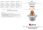
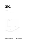
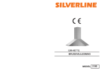
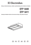
Istruzioni per l'uso e l'installazione
IT
Use and installing instructions
EN
Bedienungs und Wartungsanleitung
DE
Model : Ceiling Ovale
IT
CAPPA ASPIRANTE - Istruzioni d’uso e manutenzione
GB
COOKER HOOD - Use and maintenance instructions
DE
DUNSTABZUGSHAUBE - Bedienungs und Wartungsanleitung
520mm
115mm
230mm
115mm
56,3mm
700mm
380mm
34mm
A
Min 660 mm
A1
2
B
Min 330 mm
B1
C1
520mm
533mm
230mm
11320mm
700mm
C2
24,5mm
380mm
65mm
C3
46,8mm
23,4mm
23,4mm
49mm
115mm
328mm
115mm
49mm
3
Vedi dima di foratura
See drilling template
Bohrschablone
F1
F2
F3
F4
F5
F6
F8
F9
F7
4
IT- Installazione Telecomando
EN - Remote Control Setup
DE - Funksteuerung Einstellung
IT - Per mettere in comunicazione cappa e telecomando premere contemporaneamente,
per alcuni secondi, il tasto E (luce) del comando cappa e il tasto in alto a sinistra del
telecomando.
EN - To set the cooker hood and remote control press simultaneously the light push button
(E) on the hood and the button on upper left corner in the remote control for few seconds.
DE - Um die Haube mit der Fernbedienung in Verbindung zu setzen, drücken Sie fuer einige
Sekunden gleichzeitig die Lichttaste (E) der Haube und die Taste oben links der
Fernbedienung.
INSTALLAZIONE CON MOTORE REMOTO
La cappa può essere installata anche con motore remoto seguendo quanto descritto nelle
istruzioni poste all’interno del kit di installazione che si trova all’interno della cappa.
REMOTE ENGINE INSTALLATION
The cooker hood can be installed with remote engine according to the instruction inside
the installation kit.
INSTALLATION MIT REMOTE MOTOR
Die Haube kann auch in der Version fuer Remote Motor installiert werden, indem Sie die
Anweisungen befolgen,welche im Installations Kit innerhalb der Verpackung befinden.
L
A
B
C
D
1
2
E
5
MANUALE INSTALLAZIONE ED USO
IT
GENERALITA’
Leggere attentamente il contenuto del presente
libretto in quanto fornisce importanti indicazioni
riguardanti la sicurezza di installazione, d’uso e
di manutenzione. Conservare il libretto per ogni
ulteriore consultazione.
ISTRUZIONI D’USO
QUADRO COMANDI (Fig.L)
- Luce ON/OFF
-Riduce la velocità di aspirazione (da 4 a 1).
-ON/OFF. Accende la cappa in prima velocità 1.
Spegne la cappa a qualsiasi velocità.
- Aumenta la velocità di aspirazione (da 1 a 4).
-TIMER - Attiva la funzione timer che spegne
automaticamente la cappa dopo 15 minuti.
Quando la velocità di aspirazione è impostata
su 4 il timer si attiva automaticamente. La
velocità di aspirazione verrà automaticamente
impostata su 3 dopo 15 minuti.
TELECOMANDO (Fig. I)
AVVERTENZE PER LA SICUREZZA
• Non fare cucine alla fiamma, flambè, sotto la
cappa.
• Nel caso in cui nella stanza vengano utilizzati
simultaneamente sia la cappa che altri apparecchi
non alimentati da energia elettrica (es. stufe a
pellet), bisogna provvedere ad areare il locale.
• Evitare fornelli accesi liberi (non utilizzati).
• Controllare costantemente i cibi fritti per evitare
che l’olio surriscaldato prenda fuoco.
• Non toccare le lampade dopo un uso protratto
dell’apparecchio.
• Non cercare di controllare i filtri con la cappa in
funzione.
• Limitare l’uso della cappa a ciò che è stata
progettata: abbattere gli odori di cucina.
Non utilizzarla per altri impieghi.
• Si consiglia di mettere in funzione la cappa poco
prima di procedere a qualsiasi operazione di
cottura e di lasciarla in funzione dopo la cottura
per almeno 10 minuti e comunque fino a quando
ogni odore non sia scomparso.
PULIZIA E MANUTENZIONE
• Il buon funzionamento della cappa è condizionato
dall’assiduità con cui sono effettuate le operazioni
di manutenzione, in modo particolare, del filtro
antigrasso, e del filtro al carbone attivo.
6
• Prima di procedere a qualsiasi operazione di
pulizia scollegare l’apparecchio dal collegamento
elettrico sfilando la spina o agendo sull’ interruttore
generale.
• Pulire frequentemente tutti i depositi sul ventilatore
e sulle altre superfici, usando un panno inumidito
con alcool denaturato o detersivi liquidi neutri non
abrasivi.
FILTRI ANTIGRASSO METALLICI
I filtri antigrasso hanno il compito di trattenere
le particelle grasse in sospensione nell’aria,
pertanto sono soggetti ad intasarsi in tempi variabili
relativamente all’uso dell’apparecchio.
In ogni caso, per prevenire il pericolo di eventuali
incendi, al massimo dopo 2 mesi è necessario pulire
i filtri eseguendo le seguenti operazioni:
• Togliere i filtri dalla cappa e lavarli con una
soluzione di acqua e detergente liquido neutro,
lasciando rinvenire lo sporco.
• Sciacquare abbondantemente con acqua tiepida
e lasciare asciugare.
I filtri possono essere lavati anche in lavastoviglie.
Dopo alcuni lavaggi si possono verificare delle
alterazioni del colore. Questo non dà diritto a
reclamo per l’eventuale sostituzione dei pannelli.
ISTRUZIONI PER L’INSTALLAZIONE
L’apparecchio può essere installato in 2 modalità:
• (Fig. A): l’aria aspirata viene purificata attraverso
i filtri antigrasso metallici e convogliata all’esterno
attraverso un tubo tramite l’apposita condotta
esterna dell’abitazione. Questa installazione
prevede che lo spazio tra controsoffitto e soffitto
sia minimo di 660 mm, con motore installato alla
struttura in posizione verticale (Fig. A1).
• (Fig. B): l’aria aspirata viene purificata attraverso
i filtri antigrasso metallici e convogliata all’esterno
attraverso un tubo tramite l’apposita condotta
esterna dell’abitazione. Questa installazione
prevede che lo spazio tra controsoffitto e soffitto
sia minimo di 330 mm, in questo caso il motore
deve essere applicato alla struttura in posizione
orizzontale (Fig. B1).
A CAUSA DELLE COMPLESSITÀ DELL’APPARECCHIO SI
CONSIGLIA CHE L’INSTALLAZIONE VENGA EFFETTUATA
DA PERSONALE SPECIALIZZATO, RISPETTANDO TUTTE
LE NORMATIVE VIGENTI ED IN PARTICOLARE QUELLE
RELATIVE ALLO SCARICO DELL’ARIA DA EVACUARE E AL
COLLEGAMENTO ELETTRICO. IL PRODUTTORE DECLINA
QUALSIASI RESPONSABILITÀ PER DANNI DOVUTI AD UNA
INSTALLAZIONE NON CORRETTA O NON CONFORME ALLE
REGOLE DELL’ARTE.
IMPORTANTE
•L’apparecchio deve essere installato ad un’altezza
minima di 650 mm dai fornelli elettrici, o 750 mm
dai fornelli a gas o misti.
•Se dovesse essere usato un tubo di connessione
composto di due o più parti, la parte superiore
deve essere all’esterno di quella inferiore.
•Non collegare lo scarico della cappa ad un
condotto in cui circoli aria calda o utilizzato per
evacuare fumi degli apparecchi alimentati da
un’energia diversa da quella elettrica.
•Nel caso in cui nella stanza vengano utilizzati
sia la cappa che apparecchi non azionati da
energia elettrica si deve provvedere a creare una
areazione sufficiente dell’ambiente.
•Per i vari montaggi utilizzare viti e tasselli ad
espansione idonei al tipo di muro (es. cemento
armato, cartongesso, ecc). Nel caso in cui le viti
e i tasselli siano forniti in dotazione con il prodotto
accertarsi che siano idonei per il tipo di parete in
cui deve essere fissata la cappa.
INSTALLAZIONE
• Visionare attentamente i dimensionali (Fig. C1/
C2/C3);
• Fissare il motore, in funzione dell’ installazione
scelta (Fig. A/A1 o B/B1 );
• Praticare il foro cappa (Fig. F1) e i relativi fori
di fissaggio utilizzando l’apposita dima a corredo;
• Inserire e fissare le due staffe di ancoraggio (Fig.
F2/F3);
• Applicare un tubo estensibile, di lunghezza
necessaria all’installazione (da acquistarsi a
parte); collegare la spina alla presa di corrente;
Prendere la cappa e fissarla alle due staffe (Fig.
F4/F5/F6);
• Agganciare i filtri (Fig.F6);
• Applicare la cornice di acciaio alla cappa
precedentemente installata (Fig.F8);
è necessario interporre tra l’apparecchio e la rete
un interruttore omnipolare con apertura minima
tra i contatti 3 mm, dimensionato al carico e
rispondente alle norme vigenti.
CONTROLLO FUNZIONALE
Verificare l’accensione del motore a tutte le velocità
e l’illuminazione.
DISMISSIONE DEGLI ELETTRODOMESTICI
La direttiva Europea 2002/96/CE sui
rifiuti di apparecchiature elettriche ed
elettroniche (RAEE), prevede che gli
elettrodomestici non debbano essere
smaltiti nel normale flusso dei rifiuti solidi
urbani. Gli apparecchi dismessi devono essere
raccolti separatamente per ottimizzare il tasso di
recupero e riciclaggio dei materiali che li compongono
ed impedire potenziali danni per la salute e l’ambiente.
Il simbolo del cestino barrato è riportato su tutti i
prodotti per ricordare gli obblighi di raccolta separata.
Per ulteriori informazioni, sulla corretta dismissione
degli elettrodomestici, i detentori potranno rivolgersi
al servizio pubblico preposto o ai rivenditori.
SI DECLINA OGNI RESPONSABILITÀ PER EVENTUALI DANNI
PROVOCATI DALLA INOSSERVANZA DELLE SUDDETTE
AVVERTENZE. LA GARANZIA NON E’ VALIDA NEL CASO DI
DANNI DERIVANTI DALLA INOSSERVANZA DELLE SUDDETTE
AVVERTENZE.
COLLEGAMENTO ELETTRICO
Verificare che la tensione di rete sia adeguata a
quella richiesta par l’alimentazione della cappa
come indicato sulla targhetta applicata all’interno
dell’ apparecchio.
L’apparecchio è costruito in classe II, perciò
nessun cavo deve essere collegato alla presa
di terra. L’allacciamento alla rete elettrica deve
essere eseguito come segue:
MARRONE= L linea
BLU= N neutro
Se non prevista, montare sul cavo una spina
normalizzata per il carico indicato nella etichetta
caratteristiche.
Se provvista di spina, la cappa deve essere
installata in modo tale che la spina sia accessibile.
Nel caso di collegamento diretto alla rete elettrica
7
USE AND INSTALLING INSTRUCTIONS
EN
WARNING: unplug the appliance or switch off the circuit
breaker before carrying out maintenance operations.
METAL ANTI-GREASE FILTERS
GENERAL INSTRUCTIONS
Carefully read the following important information
regarding installation safety and maintenance.
Keep this information booklet accessible for further
consultations.
USE INSTRUCTIONS
CONTROL PANEL (Fig.L)
- Light ON/OFF
-Reduce fan speed (4 to 1)
-ON/OFF. Switch on the cooker hood at speed 1.
Switch off the cooker hood at any speed.
-Increase fan speed (1 to 4)
-TIMER - Activate the timer function.
The timer will automatically switch off the fan
after 15 minutes. When the fan speed is set
to 4 the timer activates automatically. After 15
minutes of activity the fan will automatically
switch to speed 3.
REMOTE CONTROL (Fig.I)
SAFETY WARNINGS
• The hood has been designed to remove the
kitchen smells; any other additional use shall be
regarded as non-intended.
• Aerate the room if other appliances that are not
supplied by electrical power are being used while
the hood is on.
• Do not leave the cooker on if it is not being used.
•Do not flambé food directly under the cooker
hood to prevent the grease filter catching fire due
to flames.
•Constantly check food frying to avoid that the
overheated oil may become a fire hazard.
•Do not check the status of the filters while the
cooker hood is operating.
•Do not touch the light bulbs after appliance use.
USE AND MAINTENANCE
It is recommended to switch on the appliance
before cooking. It is also recommended to leave
the appliance in operation for 10 minutes after
cooking is terminated in order to completely
eliminate cooking vapours and odours.
The proper function of the cooker hood is
conditioned by the regularity of the maintenance
operations, in particular, the active carbon filter.
Clean the fan and other surfaces of the cooker
hood regularly using a cloth moistened with
denatured alcohol or non abrasive liquid detergent.
8
The metal anti-grease filters capture the grease
particles of the vapours that develop during
cooking, therefore they are subject to clogging
according to the frequency of the use of the
appliance.
In order to prevent fire hazard, it is recommendable to clean the filter every 2 months by carrying
out the following instructions:
• Remove the filters from the cooker hood and
wash them in a solution of water and neutral
liquid detergent, leaving to soak.
• Rinse thoroughly with warm water and leave to
dry.
The filters may also be washed in a dishwasher.
The aluminium panels may alter in colour after
several washes. This is not cause for customer
complaint nor replacement of panels.
INSTALLING INSTRUCTIONS
This hood has been arranged to be installed above
a cooktop. It can be used in 2 ways:
• (Fig. A): the air is purified through the metal grease
filters and discharged to the outside through a tube
through the appropriate conduct outside of the
house. This installation provides that the space
between the false ceiling and the ceiling is at least
660 mm, with the engine installed to the structure
in a vertical position (Fig. A1).
• (Fig. B): the air is purified through the metal grease
filters and discharged to the outside through a tube
through the appropriate conduct outside of the
house. This installation provides that the space
between the false ceiling and the ceiling is at least
330 mm, in this case, the engine must be applied
to the structure in a horizontal position (Fig. B1).
WE SUGGEST TO HAVE INSTALLATION CARRIED OUT BY
QUALIFIED PERSONNEL, IN COMPLIANCE WITH ALL THE
CURRENT REGULATIONS AND IN PARTICULAR WITH THE
ONES CONCERNING AIR EXHAUST AND ELECTRICAL
CONNECTION.THE MANUFACTURER CANNOT BE HELD
LIABLE FOR DAMAGES CAUSED BY IMPROPER INSTALLATION
OR IF IT HAS NOT BEEN CARRIED OUT ACCORDING TO THE
STATE-OF-THE-ART.
IMPORTANT
•The appliance must be installed at a minimum
height of 650 mm from an electric cooker stove,
or 750 mm from gas or combined cooker stoves.
•If a connection tube composed of two parts is
used, the upper part must be placed outside the
lower part.
•Do not connect the cooker hood exhaust to
the same conductor used to circulate hot air
or for evacuating fumes from other appliances
generated by other than an electrical source.
•Take care when the cooker hood is operating
simultaneously with an open fireplace or burner
that depend on the air in the environment and
are supplied by other than electrical energy,
as the cooker hood removes the air from the
environment which a burner or fireplace need for
combustion.
•Provide adequate ventilation in the environment
for a safe operation of the cooker hood.
•Follow the local laws applicable for external air
evacuation.
• Use screws and screw anchors suitable for wall
(e.g. reinforced cement, plasterboard) for the
mounting of the cooker hood. Where screws and
screw anchors are supplied ensure that they are
suitable for the type of wall where the cooker
hood is to be mounted.
INSTALLATION
•• Drill
hole thethe
size,
suchhood
as asize
template
placed
See a
carefully
cooker
(Fig. C1/C2
in the image D.
C3),
Secure the
themotor,
motordepending
accoding to
•• Secure
on the
the installation
installation
choise
(Fig. A,
A/A1
B/B1)
option (Fig.
B or-C),
with .the screws in the kit
• inside
Realize
cooker hood and fixing bracket
thethe
hood.
holes according
the drilling
(Fig. F1),
• Apply
an extendable
hose,template
length required
for
• installation
Insert and fix
theseparately),
two fixing bracket
(Fig.of F2/
(sold
the output
the
F3),
motor and secure it with a clamp (Fig. E).
Apply
extensible
tube,the
length
required
for
•• Lift
the an
hood
and connect
plug to
the power
installation
(sold
separately);
connect
the
plug
outlet (Fig. E).
to the socket, take the cooker hood and fix it to
• Fit the hood into the hole previously created, and
the bracket (Fig. F4/F5/F6),
secure with n. 8 screws and n. 8 plugs (Fig. F).
• Assembly the filters (Fig. F6),
•• Apply
frame of
to the
the hood
hood previously
previously
Apply the
the steel
steel frame
installed
(Fig.
G).
installed (Fig.F8);
• Secure with n. 6 screws to the hood the steel
frame (Fig. H).
standards.
FUNCTIONAL CONTROL
Please control all motor speed and the on / off lights.
DISPOSAL OF OLD ELECTRICAL APPLIANCES
The European Directive 2002/96/EC on
Waste Electrical and Electronic Equipment
(WEEE), requires that old household
electrical appliances must not be disposed
of in the normal unsorted municipal waste
stream. Old appliances must be collected separately
in order to optimise the recovery and recycling of the
materials they contain and reduce the impact on
human health and the environment. The crossed-out
dustbin symbol on the product reminds you of your
obligation regarding separated waste collection.
Consumers should contact their local public service
or their local dealer for more information on the correct
disposal of exhausted household appliances.
THE MANUFACTURER DECLINES ALL RESPONSIBILITY FOR
EVENTUAL DAMAGES CAUSED BY BREAKING THE ABOVE
WARNINGS. THE WARRANTY IS NOT VALID IN THE CASE OF
DAMAGE CAUSED BY FAILURE TO COMPLY WITH THE ABOVE
WARNINGS.
ELECTRICAL CONNECTION
Check that the mains voltage is adequate as required
par the power of the hood as shown on the data
plate inside the ‘unit.
The device is manufactured as a class II, therefore
no cable must be connected to the earth. The
connection to the mains must be carried out as
follows:
BROWN = L line BLUE = N neutral
If not provided, on a standardized plug corresponding
to the load indicated on the description label.
Where a plug, the hood must be installed so that the
plug is accessible. In the case of direct connection
to the mains must be placed between the device
and a network switch with a minimum contact
opening of 3 mm, the electrical load and local
9
BEDIENUNGS UND WARTUNGSANLEITUNG
DE
ALLGEMEINES
Lesen
Sie
diese
Bedienungsanleitung
bitte aufmerksam durch, da sie wichtige
Sicherheitshinweise hinsichtlich der Installation,
dem Gebrauch und der Wartung des Gerätes
enthält. Bewahren Sie die Bedienungsanleitung für
mögliche zukünftige Fragen oder Probleme bitte
auf.
BEDIENUNG UND WARTUNG
STEUERPULT
- Licht ON/OFF
- Verringert die Ansauggeschwindigkeit (von 4 auf 1)
-ON/OFF. Schaltet die Abzugshaube in Stufe 1
ein. Schaltet sie aus, egal in welcher Stufe.
-Erhöht die Ansauggeschwindigkeit (von 1 auf 4)
-TIMER - Aktiviert die Timer-Funktion, die die
Abzugshaube automatisch nach 15 Minuten
abschaltet. Ist die Ansauggeschwindigkeit auf
Stufe 4 eingestellt, wird der Timer automatisch
aktiviert. Die Ansauggeschwindigkeit wird
nach 15 Minuten automatisch auf Stufe 3
zurückgeschaltet.
FERNBEDIENUNG ALS SONDERAUSSTATTUNG (Abb.I).
VORSICHT!
Elektrogeräte können unter gewissen Umständen
gefährlich sein!
•Kontrollieren Sie niemals die Filter, wenn die
Dunstabzugshaube in Betrieb ist.
•Fassen Sie die Lämpchen nach längerem
Betrieb der Dunstabzugshaube nicht an.
•Es ist verboten, unter der Dunstabzugshaube
Speisen zu flambieren.
•Offenes Feuer ist unbedingt zu vermeiden, da
dieses die Filter beschädigen und einen Brand
verursachen kann.
•Kontrollieren Sie beim Frittieren die Speisen
ständig, um eine Entzündung des Öls zu
vermeiden.
•Vor jeglichen Wartungsarbeiten unbedingt den
Netzstecker aus der Steckdose entfernen.
REINIGUNG UND PFLEGE
• Das reibungslose Funktionieren der Haube
wird durch die regelmäßigen Wartungsarbeiten
gewährleistet, dies betrifft ins Besondere die
Reinigung der Metallfettfilter wie auch den
regelmäßigen Austausch des Kohlefilters.
10
Vor jeder Reinigung muss das Gerät von der
Stromversorgung getrennt werden.
• Reinigen Sie regelmäßig die Ablagerungen
auf der Oberfläche und auf dem Lüfter mit
einem leicht feuchten Tuch ohne scheuernde
Reinigungsmittel.
Bitte beachten Sie für die Installation im
Abluftbetrieb, daß der Querschnitt des
Abluftrohres über die gesamte Länge den
Durchmesser von 150 mm nicht unterschreiten
darf.
FETTFILTER AUS METALL
Die Fettfilter haben die Aufgabe, die Fettpartikel
in der Luft zu binden; die Sättigung der Filter
hängt daher von der Häufigkeit ab, mit der die
Dunstabzugshaube betrieben wird.
Um eine mögliche Brandgefahr zu verhindern,
muss der Filter auf jeden Fall spätestens alle zwei
Wochen wie folgt gereinigt werden:
•Entnehmen
Sie
die
Filter
aus
der
Dunstabzugshaube und waschen Sie sie mit
einem Gemisch aus Wasser und flüssigem
Neutralreiniger.
•Wenn notwenig, lassen Sie die Verschmutzungen
kurz einweichen.
•Gründlich mit lauwarmem Wasser abspülen und
abtrocknen lassen. Sie können die Filter auch in
der Geschirrspülmaschine reinigen.
Nach mehrmaligem Waschen der Aluminiumfilter
können Farbveränderungen auftreten.
Daraus resultiert jedoch kein Anspruch auf einen
kostenlosen Ersatz dieser Teile des Geräts.
INSTALLATIONSANWEISUNG
Das Gerät kann in 2 Arten installiert werden:
•(Abb. A): Der Motor wird direkt oberhalbauf
der Deckenhaube installiert und die Abluft
vertikal nach oben abgeführt. Diese Installation
sieht vor, dass der Raum innerhalb der Decke
mindestens 660 mm Platz bietet (Abb.A1).
•(Abb. B): Der Motor wird seitlich auf der
Deckenhaube installiert und die Abluft vertikal
abgeführt. Diese Installation sieht vor, dass der
Raum innerhalb der Decke mindestens 330 mm
Platz bietet (Abb.B1).
WIR EMPFEHLEN DEN ANSCHLUSS UND DIE MONTAGE VON
QUALIFIZIERTEM FACHPERSONAL VORNEHMEN ZU LASSEN.
DER HERSTELLER ÜBERNIMMT FÜR SCHÄDEN, WELCHE
AUS UNSACHGEMÄSSER INSTALLATION ENTSTANDEN SIND,
KEINERLEI HAFTUNG.
WICHTIG
• Das Gerät muss in einer Mindesthöhe von 650
mm über dem Herd, oder 750 mm von der Gasoder gemischten installiert werden.
• Falls ein Verbindungsrohr aus zwei oder
mehreren Teilen zusammengesetzt werden,
muss der obere Teil über den unteren sein.
• Schließen Sie die Dunstabzugshaube nicht mit
einem anderen Rohr wo heiße Luft zirkuliert
oder welches zur Entlüftung von anderen
Geräten gebraucht wird.
• Bitte beachten Sie unbedingt, dass Sie im
Abluftbetrieb dem Küchenraum genügend
Frischluft zuführen. Bitte beachten Sie ebenfalls
die örtlichen Bestimmungen in Bezug auf
Abluftsysteme.
INSTALLATION
• Überprüfen Sie sorgfältig die Masse (Bild C1 /
C2 / C3);
• Befestigen Sie den Motor in Funktion der
ausgewaehlten Installation (Bild A / B oder A1
/ B1.);
• Bohren Sie das Loch in welches die Haube
eingefuehrt werden muss (Bild F1.) sowie die
Befestigungslöcher mit der entsprechenden
Schablone;
• befestigen Sie die beiden Winkel und ziehen Sie
die beiden Ankerhalterungen an (Fig.F2 / F3);
• Montieren Sie ein flexibles Rohr mit der
erforderten Laenge zur Installation, (separat
erfordern oder einkaufen); den Stecker in die
Steckdose einfuehren;
Die Haube an den zwei Befestigungswinkel
befestigen (Fig.F4 / F5 / F6);
• Fuehren Sie die Filter ein (Fig.F6);
• Montieren Sie den Stahlrahmen an die installierte
Haube (Fig.F8);
Überprüfen Sie das Einschalten des Motors bei den 4
Geschwindigkeiten sowie die Beleuchtung.
ENTSORGUNG VON ELEKTROALTGERÄTEN
Gemäß der Europäischen Richtlinie
00/96/EC über Elektro- und ElektronikAltgeräte
(WEEE)
dürfen
Elektrohaushalts-Altgeräte nicht über
den
herkömmlichen
Haushaltsmüllkreislauf entsorgt werden. Altgeräte
müssen separat gesammelt werden, um die
Wiederverwertung und das Recycling der
beinhalteten Materialien zu optimieren und die
Einflüsse auf die Umwelt und die Gesundheit zu
reduzieren.
Das
Symbol
„durchgestrichene
Mülltonne“ auf jedem Produkt erinnert Sie an Ihre
Verpflichtung,
dass
Elektrohaushaltsgeräte
gesondert entsorgt werden müssen. Endverbraucher
können sich an Abfallämter der Gemeinden wenden,
um mehr Informationen über die korrekte Entsorgung
ihrer Elektrohaushaltsgeräte zu erhalten.
FÜR SCHÄDEN, DIE AUF DIE NICHTBEACHTUNG DER OBEN
GENANNTEN ANWEISUNGEN ZURÜCKZUFÜHREN SIND,
WIRD KEINERLEI VERANTWORTUNG ÜBERNOMMEN UND DIE
GARANTIE ERLISCHT SOFORT.
ELEKTROANSCHLUSS
Die Dunstabzugshaube gehört zur Geräteklasse
II, daher müssen keine Leitungen geerdet
warden. Der anschluss an das Stromnetz ist
folgendermassen durchzuführen.
BRAUN = L Leitung
BLAU = N Neutrale Linie
Falls nicht vorhanden, muss ein Normstecker mit
den auf dem Typenschild angegebenen Werten
an das Kabel angeschlossen warden. Wenn
die Dunstabzugshaube mit einem Netzstecker
ausgestattet ist, muss sie so installiert werden,
dass der Stecker gut zugänglich ist.
Beim Direktanschluss an das Stromnetz muss
zwischen Gerät und Stromnetz ein der Netzlast
und den geltenden Vorschriften entsprechender
Mehrpolstecker mit einer Mindestöffnung von 3
mm zwischen den Kontakten installiert werden.
FUNKTIONSKONTROLLE
11
3LIOOV
09 settembre, 2014