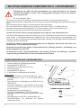
1
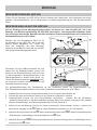
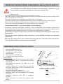
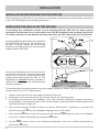
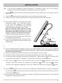
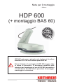
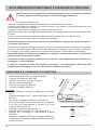
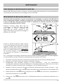
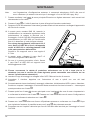
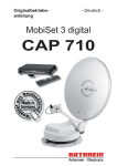
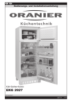
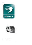
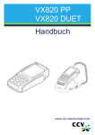
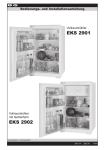
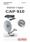
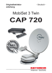
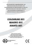
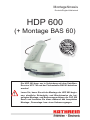
Montagehinweis
Deutsch/Englisch/Italienisch
HDP 600
(+ Montage BAS 60)
Die HDP 600 kann nur in Verbindung mit dem SatellitenReceiver UFS 740 und der Flachantenne BAS 60 betrieben
werden!
Lesen Sie, bevor Sie mit der Montage der HDP 600 beginnen, sämtliche Sicherheits- und Warnhinweise der beigelegten Montage- und Bedienungsanleitung der CAP 600
durch und beachten Sie diese während des kompletten
Montage-, Demontage- bzw. eines Umbauvorganges.
WICHTIGE HINWEISE/ KOMPONENTEN U. LIEFERUMFANG
Die Montage der HDP 160 sollte grundsätzlich von einem Fachmann (z. B. CaravanHändler) durchgeführt werden. Bei unsachgemäßer Montage erlischt der Gewährleistungsanspruch!
Es ist zu beachten, dass:
- Die Antenne und die an der Antenne angeschlossenen Geräte vom Stromnetz getrennt sind
- Die montierende Person schwindelfrei ist und sich sicher auf dem Wohnwagen bzw. Wohnmobil bewegen
kann
- Die montierende Person festes und rutschsicheres Schuhwerk trägt
- Die montierende Person während der Ausführung eine sichere Stand- und Haltepositon hat
- Das Dach und die benutzte Aufstiegshilfe (z. B. Leiter) trocken, sauber und rutschfest sind
- Das Dach der Belastung durch die montierende Person Stand hält
Vorsicht! Es besteht Lebens-/Verletzungsgefahr durch Absturz oder Dachdurchbruch!
- Sich bei der Montage/Demontage der Dreheinheit und der Flachantenne keine Personen, insbesondere
keine Kinder, in unmittelbarer Nähe der Dreheinheit bzw. der Antenne befinden und bewegliche Teile
berühren. Es darf sich während der Montage/Demontage niemand im Wohnwagen-/Wohnmobil-Bereich
unterhalb der Antenne befinden.
Vorsicht! Es besteht Lebens-/Verletzungsgefahr durch möglichen Durchbruch und durch evtl.
herabfallende Teile im Wohnmobil/-wagen
Beachten Sie weiterhin das Kapitel „Sicherheitshinweise - Wichtige Hinweise“ der Montage- und
Bedienungsanleitung CAP 600!
Im Drehbereich (siehe „Sicherheitshinweise und wichtige Hinweise“ der Montage- und Bedienungsanleitung CAP 600) dürfen sich keine Hindernisse befinden!
KOMPONENTEN UND LIEFERUMFANG
1.
2.
3.
4.
5.
6.
Dachdurchführung mit Befestigungsmutter
Montageplatte für HDP 600
Dreheinheit mit integrierter Steuerung
Antennentragarm
Montageplatte für BAS 60
2 Schrauben zur Befestigung der BAS 60
Lieferumfang:
•
Dreheinheit komplett mit Steuerelektronik (3. und 4.)
•
Montageplatten (2. und 5. - je eine für HDP 600 und
BAS 60)
•
Zwei Schrauben zur Befestigung der BAS 60 an der
HDP 600 (6.)
•
Kompletter Kabelsatz: 1 x Koax-Kabel mit 8-m-Länge
und ein Stromführungs-Kabel (10 m) zum Anschluss
an das Bordnetz
•
Dachdurchführung mit Dichtung (1.)
•
Dichtklebemasse Sikaflex® 291 (100-ml-Tube)
•
Montage- und Bedienungsanleitung MobiSet 2 digital
CAP 600
•
Montagehinweise HDP 600 (+ Montage BAS 60)
•
Sicherheitshinweis zum Absenken der Antenne
während der Fahrt
2
6.
MONTAGE
MONTAGEVORGANG HDP 600
Führen Sie die Montage der HDP 600 auf Ihrem Caravan oder Wohnmobil, unter Beachtung der angegebenen Sicherheitshinweise, wie in der Montage- und Bedienungsanleitung der CAP 600 beschrieben
durch.
MONTAGE BAS 60 AUF DIE HDP 600
Bei der Erklärung dieses Montagevorganges gehen wir davon aus, dass die HDP 600, wie in der
Montage- und Bedienungsanleitung der CAP 600 beschrieben, ordnungsgemäß aufgebaut, installiert und eingerichtet wurde. Beachten Sie bitte zusätzlich die Sicherheitshinweise der ausführlichen
Betriebsanleitung des UFS 740sw!
Bereiten Sie die Flachantenne BAS 60 für
die Montage an der HDP 600, wie in der Abbildung rechts dargestellt, vor. Führen Sie
dazu den Austausch der alten Montagehalterung an der BAS 60 durch die mit der HDP
600 mit gelieferte Montageplatte durch.
Schrauben Sie die LNB-Schutzhaube ab und
drehen Sie die Rändelschrauben heraus. Als
Ersatz für die Rändelschrauben sind bei Punkt
13 die beiliegenden Flachkopfschrauben in die
LNB-Schutzhaube zu drehen (siehe Punkt 13).
Führen Sie diesen Austausch unbedingt durch,
da sonst eine Kollision zwischen Antenne und
Automatik-Positioner erfolgt.
Zur Montage/Demontage der Flachantenne an der Dreheinheit gehen Sie folgendermaßen vor:
(Die Tastenbezeichnungen beziehen sich auf die Fernbedienung des Receivers UFS 740sw)
1.
Schalten Sie den Receiver mit dem Netzschalter an der Frontseite des Gerätes ein
2.
Drücken Sie eine der Nummern-Tasten um den Receiver in Betrieb zu nehmen
3.
Gegebenenfalls müssen Sie eine Erst-Installation durchführen - Hinweis: Bei der Einstellung
„Antennen-Konfiguration“ in der Erst-Installation muss bei dem Punkt „System“ zwingend „CAP“ gewählt
werden (siehe Montage- und Bedienungsanleitung CAP 600 „Seite 46“)!
4.
Warten Sie bis die Meldung „Position von Astra ist unbekannt. Suche starten?“ kommt – brechen Sie
dann diesen Vorgang mit der -Taste ab (diese Einblendung erscheint nur im CAP-Modus)
5.
Wechseln Sie im Anschluss mit der -Taste ins Hauptmenü und mit den -Tasten auf den Menüpunkt
„Einstellungen“ und bestätigen Sie die Auswahl mit der -Taste
6.
Wechseln Sie mit den -Tasten auf den Menüpunkt „Antennen-Konfiguration“ und bestätigen Sie die
Auswahl mit der -Taste
3
MONTAGE
Hinweis: Bei der Einstellung „Antennen-Konfiguration“ muss bei dem Punkt „System“ zwingend „CAP“
gewählt werden (siehe Montage- und Bedienungsanleitung CAP 600 „Seite 48“)!
7.
8.
9.
Wechseln Sie mit den -Tasten auf den Menüpunkt Elevation und geben Sie mit den Zifferntasten der
Fernbedienung „400“ ein
Drücken Sie die -Taste und die Dreheinheit fährt den gewählten Elevationswinkel an
Schalten Sie den UFS 740 mit dem Netzschalter an der Frontseite aus und trennen Sie ihn vom
Stromkreis
10. Montieren Sie jetzt die BAS 60, unter Berücksichtigung der benötigten Polarisationseinstellung (siehe Montage- und Bedienungsanleitung
CAP 600 „Polarisationseinstellung“) auf die HDP
600 mit Hilfe der beiden mitgelieferten Schrauben
(siehe Grafik rechts)
Beachten Sie dabei, dass sich das Sat-ZFKabel der HDP 600 in der für das Kabel vorgesehenen Aussparung an der HDP 600 und dem
LNB-Gehäuse an der Rückseite der Antenne
befindet, damit es nicht beschädigt wird.
Ziehen Sie die Innensechskant-Schrauben mit
einem Drehmoment von 6-7 Nm an
6-7 Nm
11. Verbinden Sie jetzt das Sat-ZF-Kabel der
HDP 600 mit dem LNB-Eingang der BAS 60
12. Befestigen Sie, sofern noch nicht geschehen, das
Sat-ZF-Kabel der HDP 600 in der Kabelhalterung
des LNB-Gehäuses
13. Befestigen Sie die LNB-Schutzhaube wieder an der Antenne mit den beiliegenden Flachkopfschrauben (nicht mit den alten Rändelschrauben, dies würde zu einer Kollision zwischen Antenne und Automatik-Positioner führen!!)
14. Verlassen Sie den Montageort und schließen Sie den UFS 740sw wieder an den Stromkreis an
15. Schalten Sie den Receiver zuerst mit dem Netzschalter und anschließend mit einer der NummernTasten ein
16. Als nächstes wird Ihnen „Bitte warten, HDP wird initalisiert“ angezeigt. Warten Sie bis die Meldung
„Position von Astra ist unbekannt. Suche starten?“ kommt – brechen Sie diesen Vorgang mit der
Taste ab
-
17. Wechseln Sie im Anschluss mit der -Taste ins Hauptmenü und mit den -Tasten auf den Menü-
-Taste. Wechseln Sie mit den bestätigen Sie die Auswahl mit der -
punkt „Einstellungen“ und bestätigen Sie die Auswahl mit der
Tasten auf den Menüpunkt „Antennen-Konfiguration“ und
Taste
18. Wechseln Sie mit den -Tasten auf den Menüpunkt „Drehantenne zurücksetzen“ und bestätigen Sie
mit der -Taste. Nach dem die Antenne zurückgesetzt wurde, können Sie mit der -Taste zum normalen Fernsehbild zurückkehren
19. Fahren Sie jetzt mit dem Kapitel „Bedienungsanleitung CAP 600“ der Montage- und Bedienungsanleitung CAP 600 fort.
4
TECHNISCHE DATEN/SONSTIGES
Typ
HDP 600
Bestell-Nr.
20410029
Versorgungsspannung (Autobatterie)
Stromaufnahmen aus dem 12-V-Bordnetz:
- Einschaltstrom
- Satellitensuche
- TV-Empfang
- Stand-by
Stromaufnahme aus dem Receiver
Einstellbereich:
- Elevation
- Azimut
- Skew
10,9-13,8
A
Typ. 10, max. 12
Typ. 3
Typ. 1,2
Typ. 0,024
mA
Typ. 160
°
Gewicht
Verpackungs-Einheit/Gewicht
Zündsignal
Suchzeit erster Satellit
Suchzeit weitere Satelliten
Anfahrzeit LSM
V
0-80
370
-15/0/+15
kg
8,0
St./kg
1/12,75
12…24 V
(typ.) 10…120 s
(typ.) 2…30 s
2…15 s
KONFORMITÄTSERKLÄRUNG
Siehe Konformitätserklärung in der Montage- und Bedienungsanleitung
CAP 600.
ENTSORGUNGSHINWEIS
Elektronische Geräte gehören nicht in den Hausmüll, sondern müssen - gemäß Richtlinie
2002/96/EG DES EUROPÄISCHEN PARLAMENTS UND DES RATES vom 27. Januar 2003
über Elektro- und Elektronik-Altgeräte fachgerecht entsorgt werden.
Bitte geben Sie dieses Gerät am Ende seiner Verwendung zur Entsorgung an den dafür vorgesehenen öffentlichen Sammelstellen ab.
SERVICE
Sollten Sie trotz Studiums dieses Montagehinweises und der Montage- und Bedienungsanleitung der
CAP 600 noch Fragen zur Inbetriebnahme oder Bedienung haben, oder sollte wider Erwarten ein Problem
auftreten, setzen Sie sich bitte mit Ihrem Fachhändler in Verbindung.
Weiterhin steht Ihnen auch unsere Kathrein-Kunden-Hotline zur Verfügung. Telefon: 08031/184-700
5
Installation instructions
- English -
HDP 600
(+ installation of the BAS 60)
The HDP 600 can be operated only in conjunction with the
UFS 740 satellite receiver and the BAS 60 planar antenna!
Before starting the installation of the HDP 600, please read
all safety and warning instructions in the accompanying
CAP 600 installation and operating instructions and comply
with them throughout the installation, deinstallation and
any modification work.
IMPORTANT INSTRUCTIONS/ COMPONENTS AND SCOPE OF SUPPLY
The installation of the HDP 160 should always be performed by a specialist (e.g. the
caravan dealer). Improper installation will render the warranty void.
Make sure that:
- The antenna and connected units are disconnected from the power
- The person carrying out the installation does not suffer from vertigo and can move around safely on the
roof of the caravan or motor home
- The person carrying out the installation is wearing sturdy non-slip shoes
- The person carrying out the installation has a secure position to stand and hold on while working
- The roof and the climbing equipment used (e.g. ladder) are dry, clean and non-slip
- The roof can withstand the weight of the person carrying out the installation
Caution! Risk of death or injury due to falling or roof collapsing!
- No persons, especially small children, should be in the immediate area of the turntable or antenna and
touch movable parts during installation/deinstallation of the turntable and planar antenna. Nobody should
be below the antenna inside the caravan / motorhome during dismantling / installation.
Caution! Risk of death or injury due to possible roof collapsing and falling parts on the motor
home/caravan
Note also the chapter “Important safety instructions” in the CAP 600 installation and operating
instructions!
Make sure the antenna has a clear unobstructed swing path (see “Important safety instructions”
in the CAP 600 installation and operating instructions)!
COMPONENTS AND SCOPE OF SUPPLY
1.
2.
3.
4.
5.
6.
Roof gland with retaining nut
Mounting plate for the HDP 600
Turntable with integral controls
Antenna boom
Mounting plate for the BAS 60
2 screws for securing the BAS 60
6.
Items supplied:
•
Turntable complete with control electronics (3. and 4.)
•
Mounting plates (2. and 5. - one each for the HDP 600
and BAS 60)
•
Two screws for securing the BAS 60 to the
HDP 600 (6.)
•
Complete cabling set: 1 x coax cable 8 m long, and
one power supply cable (10 m) for connection to the
on-board power supply
•
Roof gland with sealing gasket (1.)
•
Sikaflex® 291 adhesive sealant (100 ml tube)
•
MobiSet 2 digital CAP 600 installation and operating
instructions
•
Installation instructions HDP 600 (+ installation
BAS 60)
•
Safety instructions for lowering the antenna whilst
driving
7
INSTALLATION
INSTALLATION PROCEDURE FOR THE HDP 600
Whilst installing your HDP 600 on your caravan or motorhome, comply with the relevant safety instructions
in the CAP 600 installation and operating instructions.
INSTALLING THE BAS 60 ON THE HDP 600
In describing this installation process we are assuming that the HDP 600 has been properly
assembled, installed and set up as described in the CAP 600 installation and operating instructions.
The safety instructions in the detailed operating manual for the UFS 740sw must also be followed!
Prepare the BAS 60 planar antenna for installation
on the HDP 600 as shown in the illustration on
the right. To do this, replace the old mounting
bracket on the BAS 60 with the mounting plate
supplied with the HDP 600.
Unscrew the LNB protective cover and unscrew
the knurled screws from it. Screw the flat-head
screws item 13 into the LNB protective cover,
replacing the knurled screws (see item 13). The
replacement is essential because otherwise a
collision will occur between the antenna and the
automatic positioner.
To dismantle/install the planar antenna from the turntable, proceed as follows: (the key names refer to the
remote control for the UFS 740sw receiver)
1.
Switch on the receiver at the main switch on the front of the unit.
2.
Pressing any of the numeric buttons will bring the receiver into operating mode.
3.
If necessary, first perform a first installation - note: If the “Antenna configuration” setting is selected in
first installation, it is essential to select “CAP” for the “System” parameter (see CAP 600 installation and
operating instructions, page 46)!
4.
Wait until the message “Position of Astra is not known. Start search?” is displayed – then abort this
procedure using the key (this message is displayed only in CAP mode)
5.
6.
8
button to go to the main menu and use the buttons to move to the “Settings”
menu item. Confirm the selection by pressing the button.
Use the buttons to move to the “Antenna Configuration” menu item. Confirm the selection by
pressing the button.
Next, press the
INSTALLATION
Note:
If the "Antenna configuration" setting is selected, it is essential to select “CAP” for the "System"
parameter (see CAP 600 installation and operating instructions, page 48)!
7.
Use the buttons to select the Elevation option and use the number keys on the remote control to
enter “400”
8.
9.
Press the button and the turntable will move to the selected elevation angle.
Switch off the UFS 740 at the main switch on the front, and disconnect it from the power.
10. Now install the BAS 60, (observing the required
polarisation setting - see “Polarisation setting”
in the CAP 600 installation and operating
instructions) on to the HDP 600, using the two
screws supplied (see diagram on the right)
Make sure that the Sat-IF cable for the HDP
600 runs in the recess provided for it on the
HDP 600 and the LNB housing at the rear of the
antenna, so that it is protected from damage.
Sleeve
Tighten the cap screws to a torque of 6-7 Nm.
11. Now connect the Sat-IF cable on the HDP 600 to
the LNB input on the BAS 60
6-7 Nm
12. If you have not already done so, secure the Sat-IF
cable on the HDP 600 in the cable bracket on the
LNB housing
#
13. Use the flat-head screws supplied to secure the LNB protective cover back on to the antenna
(do not use the old knurled screws, because otherwise a collision will occur between the antenna
and the automatic position!!)
14. Leave the installation location and reconnect the UFS 740sw to the power supply
15. Switch the receiver on firstly with the main switch and then with any of the numeric buttons
16. You will then see the message “Please wait, initialising HDP”. Wait until the message “Position of Astra
is not known. Start search?” is displayed – then abort this procedure using the button.
17. Next, press the
button to go to the main menu and use the
buttons to move to the
buttons
to move to the “Antenna Configuration” menu item. Confirm the selection by pressing the button.
“Settings” menu item. Confirm the selection by pressing the
button. Use the
18. Use the buttons to move to the menu item “Reset the motorised antenna”. Confirm the selection
button. Once the antenna has been reset, you can return to the normal TV picture
by pressing the button.
by pressing the
19. Now continue with the actions described in chapter “CAP 600 operating instructions” of the CAP 600
installation and operating instructions.
9
TECHNICAL DATA / OTHER MATTERS
Type
HDP 600
Order no.
20410029
Power supply (vehicle battery)
Power consumption from the 12 V vehicle electrical system:
- Inrush current
- Satellite search
- TV reception
- Stand-by
Current consumption from the receiver
Setting range:
- Elevation
- Azimuth
- Skew
V
10.9-13.8
A
Type 10, max. 12
Type 3
Type 1.2
Type 0.024
mA
Type 160
°
Weight
Packing unit/weight
Ignition signal
Search time for first satellite
Search time for further satellites
Search time for LSM (Last Satellite Memory)
0-80
370
-15/0/+15
kg
8.0
pc./kg
1/12.75
12…24 V
(typ.) 10…120 s
(typ.) 2…30 s
2…15 s
DECLARATION OF CONFORMITY
See the conformity declaration in the CAP 600 installation and operating
instructions.
DISPOSAL INSTRUCTION
Electronic equipment is not domestic waste - in accordance with directive 2002/96/EC OF
THE EUROPEAN PARLIAMENT AND THE COUNCIL dated 27th January 2003 concerning
used electrical and electronic appliances, it must be disposed of properly.
At the end of its service life, take this unit for disposal to an appropriate official collection
point.
SERVICE
If, despite studying these installation instructions and the CAP 600 installation and operating instructions,
you still have questions about getting started with the unit or using it correctly, or if unexpected problems
occur, please contact your specialist dealer.
10
Nota per il montaggio
- Italiano -
HDP 600
(+ montaggio BAS 60)
HDP 600 può essere azionato solo insieme al ricevitore
satellitare UFS 740 e all’antenna piatta BAS 60!
Prima di iniziare il montaggio di HDP 600, leggere tutte
le norme di sicurezza e le avvertenze contenute nelle
istruzioni per il montaggio e l’uso di CAP 600, tenendole in
considerazione durante tutta la procedura di montaggio,
smontaggio e conversione.
NOTE IMPORTANTI/COMPONENTI E STANDARD DI FORNITURA
HDP 160 deve essere montato da un tecnico specializzato (ad es. rivenditore di roulotte).
È escluso qualsiasi diritto di garanzia in caso di montaggio improprio!
È necessario verificare che:
- l'antenna e gli apparecchi collegati alla stessa siano sconnessi dalla rete elettrica
- la persona incaricata del montaggio non soffra di vertigini e sia capace di muoversi liberamente e con
sicurezza sulle roulotte o sui camper
- la persona incaricata del montaggio porti scarpe solide e antiscivolo
- la persona incaricata del montaggio abbia una posizione e un appoggio stabili e sicuri durante l'esecuzione
dei lavori
- il tetto e i mezzi di salita (per esempio la scala) siano ben asciutti, puliti e non sdrucciolevoli
- il tetto resista al carico della persona incaricata del montaggio.
Attenzione! Persiste un'imminente pericolo di morte/lesione in seguito alla caduta dal tetto o a
una rottura dello stesso!
- Durante il montaggio/lo smontaggio dell'unità di rotazione e dell’antenna piatta, accertarsi che non sostino
persone, soprattutto bambini, nelle vicinanze delle stesse e dei componenti mobili. Durante le operazioni
di montaggio e smontaggio, nessuno deve trovarsi sotto l'antenna nell'area della roulotte/camper.
Attenzione! Esiste un pericolo di morte/lesione in seguito a una possibile rottura o all'eventuale
caduta di parti nell'area della roulotte
Consultare in merito il capitolo «Informazioni di sicurezza – note importanti» delle istruzioni per il
montaggio e l’uso di CAP 600!
Il campo di rotazione (si veda «Informazioni di sicurezza – note importanti di CAP 600») delle
istruzioni per il montaggio e l’uso non deve essere intralciato da ostacoli.
COMPONENTI E STANDARD DI FORNITURA
1.
2.
3.
4.
5.
6.
Attraversamento del tetto con dado di fissaggio
Piastra di montaggio per HDP 600
Unità di rotazione con controllo integrato
Braccio portante dell'antenna
Piastra di montaggio per BAS 60
2 viti per il fissaggio di BAS 60
Dotazione:
•
Unità di rotazione completa di elettronica di comando
(3 e 4)
•
Piastre di montaggio (2 e 5 – una per HDP 600 e una per
BAS 60)
•
Due viti per il fissaggio di BAS 60 a HDP 600 (6.)
•
Kit di cavi completo: 1 cavo coassiale di 8 m di lunghezza
e un cavo per l'alimentazione di corrente (10 m) da
collegare alla rete di bordo
•
Passacavi del tetto con guarnizione (1)
•
Sigillante adesivo Sikaflex® 291 (tubetto da 100 ml)
•
Istruzioni per il montaggio e l’uso MobiSet 2 digital
CAP 600
•
Note per il montaggio HDP 600 (+ montaggio di BAS 60)
•
Informazioni di sicurezza per l’abbassamento dell’antenna
durante la marcia
12
6.
MONTAGGIO
PROCEDURA DI MONTAGGIO DI HDP 600
Montare HDP 600 nella roulotte e nel camper, nel pieno rispetto delle informazioni di sicurezza specificate,
come descritto nelle istruzioni per il montaggio e l’uso di CAP 600.
MONTAGGIO DI BAS 60 SU HDP 600
Nell'ambito della spiegazione di questo procedimento di montaggio, si suppone che HDP 600 sia
stata correttamente montata, installata e predisposta, come descritto nelle istruzioni di montaggio
e d’uso di CAP 600. Sono da osservare anche le indicazioni di sicurezza riportate nel manuale
d'istruzione dettagliato dell'UFS 740sw!
Preparare l’antenna piatta BAS 600 per
il montaggio su HDP 600 come mostrato
nella figura a destra. Procedere alla
sostituzione del vecchio supporto di mon
taggio di BAS 60 con la piastra di montaggio in
dotazione con HDP 600.
Avvitare la calotta di protezione LNB e togliere
le viti a testa zigrinata. Al posto delle viti a testa
zigrinata, avvitare nella calotta di protezione
LNB le viti a testa piatta in dotazione (si veda il
punto 13). Questa sostituzione è obbligatoria.
Se non viene eseguita, si potrebbe verificare
una collisione tra l’antenna e il posizionatore
automatico.
Per il montaggio/lo smontaggio dell'antenna piatta sull'unità di rotazione procedere nel modo seguente:
(Le denominazioni dei tasti si riferiscono al telecomando del ricevitore UFS 740sw)
1.
Accendere il ricevitore attraverso l'interruttore generale situato sul lato anteriore dell'apparecchio.
2.
Premere uno dei tasti numerici per mettere in funzione il ricevitore.
3.
Probabilmente sarà necessario eseguire la prima installazione – nota: con l’impostazione
«Configurazione antenna» alla prima installazione, è necessario selezionare «CAP» alla voce di menu
«Sistema» (si vedano le istruzioni per il montaggio e l’uso di CAP 600 «pag. 46»)!
4.
Attendere, finché non compare il messaggio «Posizione di Astra sconosciuto. Avviare la ricerca?» – interrompere questa procedura con il tasto (questa schermata viene visualizzata sono nella modalità CAP)
5.
Passare quindi con il tasto al menu principale e con i tasti alla voce di menu «Impostazioni» e
confermare la selezione con il tasto .
6.
Passare con i tasti alla voce di menu «Configurazione antenna» e confermare la selezione con il
tasto .
13
MONTAGGIO
Note:
con l’impostazione «Configurazione antenna», è necessario selezionare «CAP» alla voce di
menu «Sistema» (si vedano le istruzioni per il montaggio e l’uso di CAP 600 «pag. 48»)!
7.
Passare mediante i tasti al menu principale Elevazione e digitare attraverso i tasti numerici del
telecomando la cifra «400».
8.
Premere il tasto e l’unità di rotazione si porta all’angolo d’elevazione selezionato.
9.
Spegnere l'UFS 740 attraverso l'interruttore generale situato sul lato anteriore e scollegare l'apparecchio
dal circuito di corrente.
10. A questo punto montare BAS 60, tenendo in
considerazione la necessaria regolazione della
polarizzazione (si vedano le istruzioni per il
montaggio e l’uso di CAP 600 «Regolazione della
polarizzazione») su HDP 600 con l’ausilio delle
due viti in dotazione (si veda la figura a destra)
Per evitare danneggiamenti, assicurarsi che il
cavo Sat-FI di HDP 600 si trovi nell’apposita
cavità di HDP 600 e nell’alloggiamento LNB
sulla parte posteriore dell’antenna.
Boccola
Serrare le viti esagonali cave a una coppia di
6-7 Nm.
11. A questo punto collegare il cavo Sat-FI di
HDP 600 all’ingresso LNB di BAS 60
6-7 Nm
12. Se non si è ancora provveduto a farlo, fissare
il cavo Sat-FI di HDP 600 nel supporto cavo
dell’alloggiamento LNB.
13. Fissare nuovamente la calotta di protezione sull’antenna con le viti a testa piat ta in
dotazione (non con le vecchie viti a testa zigrinata; questo causerebbe una collisione tra l’an
tenna e il posizionatore automatico!)
14. Lasciare il luogo di montaggio e collegare infine l'UFS 740sw al circuito di corrente.
15. Accendere il ricevitore dapprima con l’interruttore di rete e quindi con uno dei tasti
numerici.
16. Successivamente viene visualizzato il messaggio «Attendere, inizializzazione HDP in corso». Attendere,
finché non compare il messaggio «Posizione di Astra sconosciuta. Avviare la ricerca?» – interrompere
questa procedura con il tasto al menu principale e con i tasti alla voce di menu «Impostazioni»
e confermare la selezione con il tasto . Passare con i tasti alla voce di menu «Configurazione
antenna» e confermare la selezione con il tasto .
Passare con i tasti alla voce di menu «Ripristinare antenna» e confermare con il tasto . Dopo
aver ripristinato l’antenna, è possibile tornare con il tasto alla schermata normale
17. Passare quindi con il tasto
18.
19. Procedere ora con il capitolo «Istruzioni per l’uso di CAP 600» delle istruzioni per il montaggio e l’uso di
CAP 600.
14
DATI TECNICI/ALTRO
Tipo
HDP 600
N. d'ordine
20410029
Tensione di alimentazione (batteria veicolo)
Assorbimento di corrente da rete di bordo da 12 V:
- Corrente di entrata:
- Ricerca del satellite
- Ricezione TV
- Stand-by
Corrente assorbita dal ricevitore
Campo di regolazione:
- Elevazione
-Azimut
- Skew
V
10,9-13,8
A
Tip. 10, max. 12
Tip. 3
Tip. 1,2
Tip. 0,024
mA
Tipo 160
°
Peso
Unità d'imballaggio/peso
Segnale di accensione
Tempo di ricerca del primo satellite
Tempo di ricerca di altri satelliti
Tempo di avviamento LSM
0-80
370
-15/0/+15
kg
8,0
Pz./kg
1/12,75
12…24 V
(tip.) 10…120 s
(tip.) 2…30 s
2…15 s
DICHIARAZIONE DI CONFORMITÀ
Si veda la dichiarazione di conformità nelle istruzioni per il montaggio e l’uso di
CAP 600.
NOTA PER LO SMALTIMENTO
Gli apparecchi elettronici non vanno smaltiti nei rifiuti urbani, bensì in maniera appropriata
conformemente alla direttiva 2002/96/CE del Parlamento europeo e del Consiglio del 27
gennaio 2003 sui rifiuti di apparecchiature elettriche e elettroniche.
Quando questo apparecchio non servirà più, portarlo presso uno degli appositi centri di
raccolta locali.
ASSISTENZA
Se dopo aver letto accuratamente le presenti note per il montaggio e le istruzioni per il montaggio e l'uso
di CAP 600 si dovessero avere ancora dubbi sulla messa in funzione e sul comando o nel caso dovessero
verificarsi complicazioni, si prega di contattare il proprio rivenditore specializzato.
15
Internet: http://www.kathrein.de
KATHREIN-Werke KG • Anton-Kathrein-Straße 1 - 3
Postfach 100 444 • 83004 Rosenheim GERMANY
936.3412/-/0708/ZWT - Technische Änderungen vorbehalten!/Technical data subject to change/ Si riservano modifi che dei dati tecnici