1
Putting the Units into Operation
3 Putting the Units into Operation
Safety information
Attention: It is essential to read the Safety Information in Chapter 1 before starting up.
Checking the package contents 8
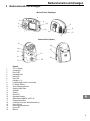
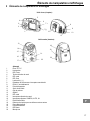
The package contains:
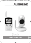
one camera unit
(transmitter)
one monitor unit
(receiver)
5 rechargeable, special NiMH
batteries for the receiver
two power adapter plugs
one audio/video cable
one belt clip
an operating manual
Connecting the transmitter
Attention: Position the transmitter with a minimum distance of 1 m to other electronic devices,
otherwise there is a risk of mutual disturbance.
Operating with a power adapter plug
Ensure you use the correct power adapter plug. The transmitter must be connected by means
of the smaller power adapter plug which has an output power of 300 mA.
Connect the cylindrical plug on the power adapter plug to the transmitter’s power supply socket
(9 V DC).
Connect the power adapter plug to a power outlet (230 V).
Operation with batteries or rechargeable batteries
Open the battery compartment on the rear side of the transmitter. Loosen and remove the screw and
slide the battery compartment cover downwards.
Insert the battery pack or batteries, paying attention to correct polarity. Refer to the diagrams in the
battery compartment.
The transmitter can be operated with 4 AA" batteries (not contained in the material supplied)
or with rechargeable batteries of the same type. Please remember that the batteries cannot
be recharged using the power adapter plug supplied. A commercially available charging unit
is required.
Close the battery compartment, reinsert and retighten the screw.
The Power LED turns orange when the battery charge is too low.
Wall installation
Be careful not to drill into electrical lines or water pipes! Ensure that no lines or pipes are under
the required installation location!
Dowels and screws are not contained in the material supplied.
Drill two holes (5 mm diameter) 38 mm apart and horizontal to each other.
Insert a dowel (5 mm diameter) in each hole.
Insert a screw (4 mm diameter) in each dowel.
Leave approx. 3 mm from the head of the screw to the wall.
Guide the recesses in the transmitter over the screw heads and pull the unit down gently.
42