1
Pag. 2 di 8
I
IMPORTANTI ISTRUZIONI DI SICUREZZA
PER L’INSTALLAZIONE
ATTENZIONE - UNA SCORRETTA INSTALLAZIONE PUÓ PORTARE A DANNI RILEVANTI
SEGUIRE TUTTE LE ISTRUZIONI PER UNA CORRETTA INSTALLAZIONE
1° - Questo libretto d'istruzioni è rivolto esclusivamente a del personale specializzato che sia a
conoscenza dei criteri costruttivi e dei dispositivi di protezione contro gli infortuni per i cancelli, le
porte e i portoni motorizzati (attenersi alle norme e alle leggi vigenti).
2° - Se non é previsto nella centralina elettrica, installare a monte della medesima un'interruttore di tipo
magnetotermico (onnipolare con apertura minima dei contatti pari a 3mm) che riporti un marchio di
conformità alle normative internazionali.
3° - Per la sezione ed il tipo dei cavi la RIB consiglia di utilizzare un cavo di tipo NPI07VVF con sezione
minima di 1,5mm2 e comunque di attenersi alla norma IEC 364 e alle norme di installazione vigenti
nel proprio Paese.
F
IMPORTANT MODE D’EMPLOI DE SECURITE
POUR L’INSTALLATION
ATTENTION - UNE INSTALLATION INCORRECTE PEUT CAUSER DE GRANDS DOMMAGES
SUIVRE TOUTES INSTRUCTIONS POUR UNE CORRECTE INSTALLATION
1° - Ce manuel d'instruction est adressé seulement au personnel specialisé qui a une
connaissance des critères de construction et des dispositifs de protection contre les accidents en ce
qui concerne les portails, les portes et les portes cochères motorisées (suivre les normes et les lois
en vigueur).
2° - A fin de procéder à l'entretien des parties électriques, connecter à l'installation un disjoncteur
differentiel magneto thermique (qui disconnait toutes les branchements de la ligne avec ouverture
min. des branchements de 3 mm ) et qui soit conforme aux normes internationales.
3° - Pour la section et le type des câbles à installer nous vous conseillons d’utiliser un cable <HAR>
avec une section min de 1,5 mm2 en respectant quand même la norme IEC 364 et les normes
nationales d'installation.
GB
IMPORTANT SAFETY INSTRUCTION
FOR INSTALLATION
WARNING -INCORRECT INSTALLATION CAN LEAD TO SEVERE INJURY
FOLLOW ALL INSTALLATION INSTRUCTIONS
1° - This instruction booklet is exclusively dedicated to specialized staff who are aware of the
construction criteria and of the accident prevention protection devices for motorized gates and
doors (according to the current regulations and laws).
2° - To maintain electrical parts safely it is advisable to equip the installation with a differential thermal
magnetic switch (onnipolar with a minimum opening of the contacts of 3mm) and must comply
with the international rules.
3° - As for electric cable type and section RIB suggests cable type <HAR> with minimum section of
1,5mm2 and however respect IEC 364 rule and general national security regulations.
D
WICHTIGE SICHERHEITSVORSCHRIFTEN
FÜR DIE INSTALLATION
ACHTUNG - EINE FALSCHE INSTALLATION KANN ZU BEDEUTENDEN SHÄDEN FÜHREN
FÜR EINE KORREKTE ANLAGE ALLE ANWEISUNGEN BEFOLGEN
1° - Diese Montageanweisung ist ausschließlich für geschultes Fachpersonal bestimmt, das
mit den Montagevorschriften und den Schutzvorrichtungen zur Verhinderung von Unfällen bei
motorisierten Toren vertraut ist (nach den aktuellen Normen und Gesetzen).
2° - Für die Wartung der elektrischen Teile ist es ratsam, zwischen der Anlage und dem
Netzanschluß einen magnetisch-thermischen Differenzialschalter (mit Mindestöffnung aller
Kontakte von 3 mm) zu montieren, der allen internationalen Normen entspricht.
3° - Für den Kabelquerschnitt und die Kabeltypen halten Sie sich an den Normen IEC 364 (MindestKabelquerschnitt von 1,5 mm2 mit der Bezeichnung <HAR>) und für die Montage an die Normen
des jeweiligen Landes.
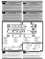
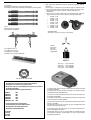
Fig. 1
ABCDEFGLM-
Elettroriduttore K600-FE
Fotocellule esterne
Cremagliera
Selettore a chiave
Antenna radio
Lampeggiatore
Limitatori di corsa
Costa meccanica
Costa pneumatica
ABCDEFGLM-
K600-FE operator
Photoelectric cells (external)
Rack
Key selector
Tuned aerial
Flashing lamp
Limit switch cam
Mechanical strip
Pneumatic strip
Electro-réducteur K600-FE
Photocellules p/protec. externe
Cremaillere
Selecteur
Antenne radio
Signal electrique
Camme en fin de course
Cordon mécanique
Cordon pneumatique
ABCDEF GL M-
Torantrieb K600-FE
Photozelle Toraussenseitig
Zahnstange
Schlußelschalter
Antenne
Blinkleuchte
Endschalter
Mechanische Kontaktleiste
Pneumatische Kontaktleiste
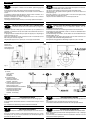
Fig. 3
Fig. 2
I
A B CDE F GL M-
CONTROLLO PRE-INSTALLAZIONE
N.B. È obbligatorio uniformare le caratteristiche del cancello alle norme e
leggi vigenti.
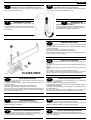
É necessario che la guida abbia alle sue estremità due fermi meccanici (L) (Fig. 2).
Inoltre, le colonne devono avere superiormente delle guide antideragliamento (Fig. 3).
Il cancello deve essere protetto da involontari sganciamenti e deve muoversi senza
attriti. N.B.: Eliminare fermi meccanici del tipo indicato descritto in figura 3.
Non devono essere presenti, al di sopra del cancello, fermi meccanici perché non
sufficientemente sicuri.
GB
PRE-INSTALLATION CHECKS
ATTENTION: It is compulsory to conform the gate characteristics to the
current regulations and laws.
The guide needs to have two mechanical stops (L) of the type indicated at its ends (Fig.
2).
In addition, the columns must have anti-deraillement guides at the top (Fig. 3).
The gate must be protected against unintentional derailment and must move without
frictions. N.B. Eliminate the mechanical stops of the type indicated in Fig. 3.
There must be no mechanical stops above the gate, as they are not safe enough.