1
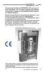
K-FACTOR SRL Stabilizzatori di tensione trifase elettromeccanici Serie RTG Istruzioni per l’uso e la manutenzione Electromechanical voltage stabiliser STABILISER WORK NO. POWER KVA INPUT VOLTAGE V± OUTPUT VOLTAGE V± RTG series Directions for use FREQUENCY 50/60 Hz Nota: Questo manuale si riferisce al modello per tensione di rete 230V monofase/400V trifase. Per altri paesi, con le medesime caratteristiche, gli stabilizzatori Ideomat sono fornibili con tensione di rete 220V o 240V (380V o 415V trifase) o altre a richiesta. Controllate che la tensione nominale dell’apparecchio corrisponda a quella del paese dove viene installato. Warning: this handbook refers to the model for network voltage of 230V single phase/400V three phase. For other countries, under the same characteristic, Ideomat stabilisers are supplied with rated voltage 220V or 240V (380V or 415V three phase). Check that the rated voltage on the plate of the apparatus is conforming to the country network one and to the installation of the stabiliser. INDICE 1. Generalità 2. Principio di funzionamento 3. Caratteristiche elettriche 4. Comandi e strumentazione 5. Istruzioni per l'installazione 6. Norme particolari per serie RTG "triangolo" 230V 7. Norme per un corretto utilizzo - Manutenzione 8. Intervento di pulizia dei variatori 9. Schemi essenziali 10. Dati tecnici 11. In caso di assistenza 12. Garanzia 1. GENERALITÀ Gli stabilizzatori trifase elettromeccanici della serie RTG a bilancia elettronica dispongono di controllo indipendente per ciascuna fase consentendo, anche in presenza di carichi squilibrati, una regolazione costante della tensione. Tre circuiti elettronici di controllo, tre servomotori e sei variatori di regolazione accoppiati garantiscono le migliori prestazioni con la massima affidabilità. Questa tipologia costruttiva rende la serie RTG adatta ad alimentare qualsiasi apparecchiatura che necessiti di una tensione di alimentazione costante, dalle macchine operatrici a controllo numerico ai centri elaborazione dati. La serie RTG, montata in un solido mobile dotato di sportello di protezione, non introduce distorsioni armoniche, è particolarmente silenziosa e assolutamente priva di dispersione magnetica. Per un corretto collegamento è importante ricordare che la linea di alimentazionedeve essere dotata di neutro. L'uscita è realizzata con un collegamento a stella delle tre apparecchiature monofase, con il neutro accessibile. 2. PRINCIPIO DI FUNZIONAMENTO Le serie RTG utilizza, per la regolazione di ogni fase, il principio del trasformatore "serie". Uno o due variatore/i, regolati tramite un circuito di comando in base alla tensione di uscita risultante, alimentano un trasformatore il cui secondario è posto in serie sulla fase. La tensione che scaturisce dal secondario del trasformatore va a sommarsi o a sottrarsi alla tensione di ingresso. La lettura continua della tensione di uscita permette al circuito di comando di fornire un impulso di rotazione al motore in c.c. che regola la tensione di uscita del variatore. Ogni modulo di fase viene collegato agli altri due con una configurazione circuitale a "stella" che comporta l'utilizzo del neutro in ingresso e la disponibilità dello stesso sull'uscita, come riportato nello schema 1. 3. CARATTERISTICHE ELETTRICHE Di seguito sono citate le caratteristiche elettriche degli apparecchi stabilizzatori. La tensione di uscita viene mantenuta costante entro il ±1% del valore nominale nelle seguenti condizioni: tensione compresa tra il ±15% della tensione nominale, ovvero tra 340V e 460V trifase (da 323V a 437V per il modello 380V) frequenza 50-60Hz carico compreso tra 0 e 100% Quando varia la tensione di ingresso, un impulso di regolazione muove la spazzola del/dei variatore/i che, attraverso il trasformatore serie, aggiunge o sottrae diversi valori di tensione per rientrare nell'errore stabilito. La velocità di regolazione è stimata in ca. 20msec. (o 30msec, a seconda dei modelli) per ogni Volt da regolare. Gli stabilizzatori della serie RTG non risentono delle variazioni del fattore di potenza (cos-phi) del carico. Il rendimento a pieno carico è ca. il 94%-98% secondo i modelli. Lo stabilizzatore è protetto da un interruttore magnetotermico quadripolare di portata adeguata di serie, se non diversamente stabilito dalla specifica tecnica del singolo prodotto. 4. COMANDI E STRUMENTAZIONE Sul pannello frontale sono presenti: a- analizzatore di rete con display visualizzazione b- commutatori per la visualizzazione della tensione su di ingresso e di uscita c- viti di regolazione della tensione della tensione di uscita d- interruttore automatico 5. ISTRUZIONI PER L'INSTALLAZIONE a. Aprire il pannello frontale con l’apposita chiave, verificando che l’interruttore automatico sia abbassato. b. Lo stabilizzatore è provvisto di una morsettiera di collegamento così composta: nr.4 morsetti denominati R,S,T,N per "ingresso" nr.4 morsetti denominati R,S,T,N per "uscita" nr.1 o 2 morsetti di terra 2 Collegare la linea di alimentazione del carico ai morsetti denominati "uscita" o "carico" rispettando la successione delle tre fasi (R,S,T) e neutro (N). Accertarsi che il carico sia spento. Collegare la tensione di rete ai morsetti denominati "ingresso" rispettando la successione delle tre fasi (R,S,T) e neutro (N). ATTENZIONE: IL COLLEGAMENTO DEL NEUTRO IN INGRESSO ALLO STABILIZZATORE È NECESSARIO, ANCHE SE NON RICHIESTO DAL CARICO. c. Richiudere il pannello e sollevare l'interruttore magnetotermico. Non appena acceso lo stabilizzatore, verificare che la potenza richiesta dal carico sia inferiore alla potenza di targa dello stabilizzatore. Per fare ciò, è opportuno misurare con una pinza amperometrica la corrente di ogni fase o utilizzare l’analizzatore di rete fornito in dotazione. La potenza assorbita da ogni fase NON DEVE SUPERARE UN TERZO della potenza di targa dello stabilizzatore. Ad esempio uno stabilizzatore da 60KVA può sopportare al massimo 20KVA su ogni fase. Un eventuale squilibrio del carico è perfettamente tollerato dallo stabilizzatore, purchè la potenza assorbita non superi il limite di un terzo della potenza di targa. I tre voltmetri indicano, per ogni fase, la tensione in entrata o in uscita a seconda che la leva sottostante sia posta rispettivamente nella posizione -in- o -out-. Per l’utilizzo dell’analizzatore di rete, fate riferimento al manuale relativo allegato e. Con un cacciavite inserito nei fori dalla denominazione "- -------- +" è possibile regolare in modo fine il punto centrale di regolazione. Girando in senso antiorario lo stabilizzatore si regola su una tensione inferiore a 400V sulla fase interessata; in senso orario la tensione diventa superiore a 400V. (Si consiglia di compiere questa operazione una sola volta, all'inizio dell'uso dell'apparecchio. In genere, tuttavia, tale operazione non si rende necessaria). 6. NORME PARTICOLARI PER SERIE RTG TRIANGOLO - 230V Nel caso abbiate acquistato uno stabilizzatore trifase in configurazione "T" (triangolo) per reti non dotate di neutro, lo schema di collegamento è riportato in allegato al n.3. Il collegamento in entrata e uscita e tutte le regolazioni vanno effettuate allo stesso modo, ricordando le seguenti avvertenze: I I morsetti di ingresso e uscita sono privi del morsetto N (neutro). Il collegamento del neutro non è previsto e non è necessario per il funzionamento dell'apparecchio. II I voltmetri in entrata e uscita leggono le tensioni tra fase e fase: RS-ST-RT. Dovranno pertanto indicare, in caso di corretto funzionamento, 230V ±15% in ingresso, 230V ±1% in uscita. 7. NORME PER UN CORRETTO UTILIZZO - MANUTENZIONE 1. Lo stabilizzatore non deve operare in ambienti polverosi o in presenza di agenti chimici corrosivi. 2. Non pulire mai la superficie dell'apparecchio con prodotti aggressivi. Non usare olio o solventi chimici. 3. Non utilizzare mai l'interruttore magnetotermico dello stabilizzatore come interruttore generale dell'apparecchio utlizzatore. Tale operazione, se ripetuta nel tempo, può a lungo andare danneggiare l'apparecchio. 4. Alcuni modelli sono dotati di ventole di raffreddamento. Fate attenzione a non coprire tali ventole per evitare l'eccessivo riscaldamento dell'apparecchio. Non appoggiare oggetti, libri o altro sul coperchio dello stabilizzatore, evitando inoltre di collocarlo vicino a fonti di calore. 5. Se vengono rispettate con cura le norme precedenti, lo stabilizzatore non richiederà interventi di manutenzione per diversi anni. E' bene, saltuariamente, verificare che su ogni fase la tensione venga regolata correttamente, controllando le tensioni in entrata e uscita. 8. INTERVENTO DI PULIZIA DEI VARIATORI Può essere necessario, con una periodicità di 30-36 mesi, effettuare una pulizia dei variatori. Per effettuare tale operazione seguire le seguenti indicazioni: 1. Scollegare lo stabilizzatore dalla rete 2. Svitare le viti dei tre pannelli frontali di fase e staccare il connettore degli strumenti 3. Portare lentamente a fine corsa il braccetto con la spazzola del variatore spostandolo con la mano 4. Utilizzando carta vetrata molto fine pulire la superficie di contatto con la spazzola, fino a quando la grafite e la polvere depositate non siano eliminate 5. Spostare leggermente il braccetto delle spazzole per pulire anche nel punto di fine corsa. Verificare, ruotando lentamente il braccetto con la mano, che il percorso della spazzola sia regolare e privo di asperità. 6. Effettuare la stessa operazione per le altre fasi e richiudere l'apparecchio. 3 9. SCHEMI ESSENZIALI A B 4 10. DATI TECNICI Tensione nominale entrata Tensione di uscita Precisione della tensione di uscita Frequenza Tempo di risposta Fattore di potenza del carico Distorsione armonica introdotta Squilibrio ammesso dal carico Rendimento a pieno carico Temperatura Potenza nom. 40KVA 50KVA 60KVA 80KVA 100KVA 150KVA 200KVA 300KVA Codice ord. RTG040K RTG050K RTG060K RTG080K RTG100K RTG150K RTG200K RTG300K 400V± 15% 400V ±1% 50-60Hz 20 millisec. per Volt qualsiasi inferiore all'1% qualsiasi 98% -10°C +40°C Disegno A A A A A B B B Dimensioni mm. 600 x 400 x h 1300 600 x 400 x h 1300 600 x 600 x h 1970 600 x 600 x h 1970 600 x 600 x h 1970 1200 x 600 x h 1970 1200 x 600 x h 1970 1200 x 800 x h 1970 Peso Kg. 280 315 350 350 380 450 500 580 Dotazione: - interruttore automatico quadripolare - analizzatore di rete digitale - 3 commutatori per l'indicazione in-out del voltmetro - regolazione fine della tensione per ogni fase - morsettiere per il collegamento alla rete e al carico 11. IN CASO DI ASSISTENZA La ditta confida in una completa collaborazione della Clientela al fine di migliorare il proprio servizio. Pertanto ricordiamo alcuni dati da riconoscere prima di interpellare il ns servizio tecnico: a. Modello della macchina......................................................................................................................... b. Numero di matricola .............................................................................................................................. c. Acquistato da.......................................................... il ........................................................................... d. Tipo di carico......................................................................................................................................... e. Assorbimento inserito............................................................................................................................ ( rilevabile sulle targhe di caratteristiche degli apparecchi) f. Difetto riscontrato................................................................................................................................... In caso di restituzione per riparazione, allegare sempre alla macchina una lettera citando i dati richiesti, insieme all'imballo originale ed in PORTO FRANCO. 5 INDEX 1. 2. 3. 4. 5. 6. 7. 8. 9. 10. 11. Generality Working principles Electrical characteristic Controls and tools Rules for installation Instructions for RTG "triangle" 230V series Instructions for a correct use - Maintenance Cleaning of variable transformers Essential schemes Technical specifications Instructions for correct transportation and warehousing 1. GENERAL DATA The RTG series electromechanical stabilisers with electronic balancing, feature independent control on each phase to allow constant voltage regulation even in the case of unbalanced loads. Three electronic control circuits, six servo motors and six paired variable transformers guarantee high level performance and dependability. This configuration makes the RTG series ideal for powering any apparatus requiring a constant voltage power supply, ranging from NC machines to computer centres. The RTG series, installed in a robust cabinet with a protective door, does not introduce harmonic distortion, is particularly silent-running and totally free from magnetic leakage. For correct connection, it is important to remember that the power line must be provided with a neutral connection. The RTG series stabilisers are fitted with automatic 4-pole switches or fused 4-pole switches, digital voltmeters with switch for input and output voltage readings on the phases R,S,T, three A-meters for current reading on each phase, terminal board for simplified connection to the mains and load. 2. WORKING PRINCIPLES The RTG series uses, for the regulation of each phases, the rule of the "buck-boost" transformer. One or more variable transformers, regulated by a control circuit according to output voltage, feed a power transformer: the secondary of the transformer is connected in series with the phase. The input voltage is increased or decreased by the voltage of the secondary winding of the transformer. The continuous reading of the output allows to the control circuit to give an impulse of rotation to the d.c. servo motor that regulates the output voltage of the variable transformers. Each phase is connected to the others through a “star” circuit configuration that allows the use of the neutral on input and the availability of the same on the output, as per scheme n.1. 3. ELECTRICAL CHARACTERISTIC The output voltage is kept constant within the ±1,5% of the nominal value in the following conditions: - voltage included between 340V and 460V three phase (from 323V to 437V for 380V type) - frequency 50-60 Hz - load included between 0 and 100% When the input voltage changes, one impulse of regulation moves the brush of variable transformer that, through the series transformer, adds or subtracts different values of voltage to return in the expected accuracy. The regulation speed is about 20/1000 sec. for each volt to be regulated. The RTG stabilisers are not affected by the load power factor variations (cos-phi). The efficiency is about 94-98% according to different models. The stabiliser is protected by a 4-pole magnetothermal circuit breaker or by a 4-pole fused circuit breaker. 4. CONTROLS AND TOOLS On the frontal panel there are: -a- Voltage analyser -b- switches for the IN/OUT voltage reading -c- screws for fine regulation of the output voltage -d- input switch. 5. RULES FOR INSTALLATION a. Remove the frontal panel opening the front door with the special key, making sure that the switch is off. b. The stabiliser is provided with a terminal board with: - 4 terminals marked R,S,T, N for "INPUT” - 4 terminals marked R,S,T, N for "OUTPUT” - 1 or 2 earth terminals Connect the feeding main of the load to the terminals marked OUTPUT following the succession of the 3ph. (R,S,T) and neutral (N). Make sure the load is off. Connect the line voltage to the terminals marked INPUT following (R,S,T) and neutral (N). Warning: the connection of the neutral on input of the stabiliser is necessary even if not requested by the load. ( only for the models 380V-400V-415V 3ph.) c. Remember to check first that the power required by the load is less than the rated power of the stabiliser measuring, with an instrument, the current for each phase. The power consumption of each phase must not 6 d. e. exceed a third of the plate power of the stabiliser. For example a 60KVA stabiliser can suffer 20KVA for each phase. Close the panel and turn on the switch. The three displays show, for each phase, the input or output voltage in accordance to the position of the switch (-in- or -out-) below. For the use of the voltage analyser, please refer to its enclosed instruction manual. With a screwdriver fitted in the holes signed "out control" it is possible to regulate carefully the central point of regulation. Turning anti-clockwise the stabiliser regulate itself on a voltage lower than 400V on the chosen phase; turning clockwise the voltage becomes higher than 400V. (We suggest to do this only once at the beginning of the working of the stabiliser). Remember that the voltmeters are showing the voltage value of each phase. I.e., the voltmeters of a 400V rated stabiliser will show a value around 230V (±1.5% ±voltmeter accuracy) 6. INSTRUCTIONS FOR RTG "TRIANGLE" 220V SERIES In case you have bought a 3ph stabiliser in configuration "T" (triangle) for networks without neutral, the connection scheme is reported in scheme 2. The connection for input and output and all the regulation must be made all in the same way, following the below notices: - The in/out terminals have got no neutral (N). The connection of the N is not foreseen and it is not necessary for the working of the apparatus. - The in/out voltmeters read the voltages between phases: RS-ST-RT. They should indicate, in case of correct working, 220V (230V) ±15% for input, 220V (230V) ±1% for output. 7. INSTRUCTIONS FOR A CORRECT USE - MAINTENANCE - The stabiliser must not work in dusted ambient or in presence of chemical corrosive material. - Do not clean the surface of the apparatus with aggressive products. Do not use oils or chemical solvents. - Do not use the magneto thermal switch of the stabiliser as general switch of the users apparatus. This operation could damage the stabiliser. - Some models are fitted with cooling fans. Take care to not cover the fans to avoid the excessive heating inside the stabiliser. Do not lay things, books or something else on the top of the stabiliser, avoiding to place it near heat sources. - If you follows the above warnings the stabiliser will not need maintenance for several years. Sometime, it is better to check that on each phase the voltage is correctly regulated reading the input and output voltages. 8. CLEANING OF VARIABLE TRANSFORMERS It can be necessary every 30-36 months to clean the surface of the variable transformers - Disconnect the stabiliser from the network. - Open the front panel - Slowly turn to the end-run the brush of each variable transformer moving it by hand. - Using very thin sand-paper clean the surface in contact with the brush, until the graphite and the dust will disappear. - Move slightly the brush to clean also the end-run. Check that the course of the brush is regular and without roughness. - Make the same operation for each phase and close the stabiliser. 7 9. ESSENTIAL SCHEMES A 10. TECHNICAL SPECIFICATIONS RTG Rated input voltage Output voltage Output voltage accuracy Frequency Response time Load power factor Harmonic distortion Tolerable load unbalanced Full load efficiency Ambient temperature *according to rated voltage required RTG-T 220V Rated input voltage Output voltage Output voltage accuracy Frequency Response time Load power factor Harmonic distortion Tolerable load unbalanced Full load efficiency Ambient temperature *according to rated voltage required B 400V 3phase +N in a.c. ±15% (415V or 380V)* 400V (415V or 380V)* ±1,5% 50-60Hz 20/1000 sec / Volt any less than 1% any 94% -10°C +40°C 220V 3phase ±15% (230V or 240V)* 220V 3phase (230V or 240V)* ±1,5% 50-60Hz 20/1000 sec / Volt any less than 1% any 98% -10°C +40°C 8 Power Item No. Dimensions (mm.) DWG 40KVA RTG040K 600X400X1300 50KVA RTG050K 600X400X1300 60KVA RTG060K 600x600x h 2040 80KVA RTG080K 600x600x h 2040 100KVA RTG100K 600x600x h 2040 150KVA RTG150K 1200x800x h 2040 200KVA RTG200K 1200x800x h 2040 Dimensions and weight may vary according to customer’s request A A A A A B B Approx. Weight Kg 280 315 350 395 430 570 680 Fitted with: - 4-pole (or 3-pole) input circuit breaker * - 3 switches for the indication in/out of the Voltmeter - 4 displays voltage analyser with input/output voltage reading - fine regulation of the voltage for each phase - terminal boards for the connection to the network and to the load * according to power and request, the stabiliser is fitted with automatic switch or fuse switch 11. INSTRUCTIONS FOR CORRECT TRANSPORTATION AND WAREHOUSING 1.The RTG stabilisers are delivered in a wooden box on a pallet. 2.For a correct warehousing, the RTG stabilisers should be placed in a protected area, with a temperature from +10°C up to 40°C, at a maximum humidity of 90%. 3.If the wooden box is taken off, the main switch must be kept in “OFF” position with the doors closed. 9 GARANZIA L'apparecchio come ogni suo componente è stato sottoposto ad accurati collaudi ed è garantito per un periodo di 24 mesi dalla data di acquisto o non oltre 25 mesi dalla data di spedizione. Per data di acquisto si intende quella indicata sulla fattura o ricevuta fiscale rilasciata dal venditore. Per garanzia si intende la sostituzione o riparazione gratuita dei componenti riconosciuti dalla ditta produttrice inefficienti o difettosi di fabbricazione. Per l'intervento in garanzia, l'apparecchio deve essere consegnato o inviato franco di porto al servizio di assistenza più vicino, allegando lettera con dati apparecchiatura descritti nel paragrafo precedente. Il trasporto avverrà a rischio e pericolo dell'acquirente. L'apparecchio riparato in garanzia verrà restituito all'acquirente appena possibile e a sue spese e rischio. Sono escluse dalla garanzia le rotture accidentali, distruzioni o folgorazioni da eventi naturali, i danni provocati da incuria, uso ed installazione errati, impropri o non conformi alle avvertenze riportate. La garanzia decade qualora l'apparecchio sia stato manomesso o riparato da personale non autorizzato o abbia subito interventi per vizi o verifiche di comodo. E' esclusa la sostituzione dell'apparecchio o il prolungamento della garanzia in caso di intervento. E' escluso altresì il risarcimento di danni diretti o indiretti di qualsiasi natura a persone, cose o animali per l'uso e la sospensione d'uso dell'apparecchio. GUARANTEE This guarantee is offered as an extra benefit and does not affect your legal rights. All the voltage stabilisers and line conditioners are guaranteed by the Company for 24 months against faulty material or workmanship. If any part is found to be defective in this way within the first twelve months from the purchase date, we or our authorised service agents, we will replace or at our option repair that part without any charge for materials or labour, provided that the appliance has been used only in accordance with the instruction provided with each stabiliser and that it has not been connected to an unsuitable electricity supply, or subjected to misuse, neglect or damage or modified or repaired by any person not authorised by us. The correct electricity supply voltage and frequency is shown on the rating plate on the appliance. This guarantee is normally available only to the original purchaser of the appliance, but the company will consider written applications for transfer. Should any defect arise in any voltage stabilisers or line conditioners a claim under guarantee become necessary, the appliance should be carefully packed and returned to your local service agent. This copy of the guarantee should be attached to the appliance. Guarantee is applied only if the equipment is returned F.O.T. our factory. No technical intervention may be claimed for any reason at the place of installation under guarantee. Cut and send to our address for the validity of the guarantee Model/type Work no. Modello No. Matricola Manuf. Year Anno fabbricazione Tested by Firma collaudo Tagliare e inviare in busta chiusa per la validità della garanzia Data di acquisto/Purchase date: _______________ Nome e indirizzo dell’acquirente/Name and address of the owner: (Inviare entro 15 gg. dalla data di acquisto/to be sent within 15 days from the purchase date) 10