1
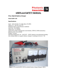
ROTARY ELECTRIC CONVERTER (THREE PHASE) The contents of this document are subject to revision without notice due to continued progress in methodology, design, and manufacturing. SHIMATSU Japan Technology User Manual IMPORTANT SAFETY WARNING ROTARY ELECTRIC CONVERTERS OPERATE AT MAINS VOLTAGES. INSTALLATION, CONNECTION AND MAINTENANCE MUST BE CARRIED OUT BY SUITABLY QUALIFIED PERSONNEL ONLY AND IN ACCORANCE WITH GOOD ENGINEERING PRACTICE. IT IS IMPORTANT THAT THE INSTRUCTION MANUAL IS CAREFULLY READ BEFORE ANY WORK IS COMMENCED NOTE: Before first time switching ON the Rotary Electric Converter must be visually inspect both externally and internally. This is to ensure that there has been no damage or that there is no dust or other foreign objects that have accumulated during transportation or installation. Pay particular care to the variable transformer brushes and tracks. NOTE: Ensure that the Rotary Electric Converter is connected to a good protective earth. NOTE: Ensure that the installation location of the Rotary Electric Converter allows adequate ventilation and is not causing overheating. NOTE: The Rotary Electric Converter may not be installed in an explosive material area or in an inflammable gas environment. NOTE: Ensure that the Rotary Electric Converter has Normal-By Pass (also marked as StableLine) transfer function. No work should be commenced at live line conditions. NOTE: Before installation Rotary Electric Converter, desiccant agent (Silica Gel) bag and residual matter should be removed from Rotary Electric Converter and surely inspected. 1 2014-07-03 Rev B SHIMATSU Japan Technology User Manual Table of content 1. Introduction 2. Features 3. Specifications 3.1 Electrical specifications 3.2 Mechanical specifications 4. Technical guide 4.1. User Interface 4.2. Part location 4.3 Control board 4.4 Auto transformer 4.5 Voltage control board (PCB1) 4.6 Over, under voltage protection board (PCB2) 5. Principle of operation 5.1 Design 5.2 Electrical principle diagram 5.3 Monitor and control circuit 5.4 Over, under voltage protection principle 5.5 Other protection circuit 6. Installation, Adjustment and Operation 6.1. Installation procedure 7 Maintenance 2 2014-07-03 Rev B SHIMATSU Japan Technology User Manual 1. Introduction STB Series Rotary Electric Converters are designed and manufactured utilizing advanced compensation technique. The Rotary Electric Converter’s offer high capacity and high efficiency. They are easy to operate, require simple maintenance and offer high reliability. The Rotary Electric Converter can match any load type, especially unmanned operation of equipment in telecommunication centers. The Rotary Electric Converter’s provide stable output voltage supply for electronic equipment such as telecom base station, CNC machines, computerized topography, printing machines, production lines and others. For up to 500KVA capacity STB Series Rotary Electric Converter’s employ roller type brush. The electrical design combines three phase overall control with independent phase adjustments. 2. Features 32bit microprocessor control system (ARM Cortex-M3) Wide input voltage range. Wide load power factor range (resistive, capacitive, inductive). Continuous operation and short time over load rated. Long life roller type carbon brush. Negligible wave distortion to the output. Isolation transformer can be connected at the input or at the output of the Rotary Electric Converter. The △/Y or Y/△ isolation transformer option offers 3rd harmonic rejection. Protection circuit (over, under voltage and over current with shutdown delays). Manual By-Pass. Normal (Stable) breaker and By-Pass (Line) breaker are mechanically interlocked. Vacuum pressure impregnation process for F or H class insulation of the magnetic components. Surge protection option is available on request. Multiple outputs or other output voltages are available on request. 3. Specifications 3.1Electrical specifications Input voltage range: Maximum allowed280V-450Vac 50Hz Non-destructive 0-500Vac 50Hz Input frequency range: 50Hz +/-5Hz Nominal output voltage: Three phase 380Vac 50Hz Over voltage shutdown: Output voltage >253Vac (+15%), 4-7s delay before cut off. Automatic restart when mains voltage decreases. Under voltage shutdown: Output voltage< 176Vac (-20%), 4-7s delay before cut off. Automatic restart when mains voltage increases. Output voltage accuracy: Selectable ±1% to 5%.Factory preset at ±1.5% Long term Stability: <±2% Overload protection: Automatic circuit breaker rated at 130% Overload capability for heavy start load. Manual By-pass: Rated for 130% nominal current. Efficiency: >98% (Without isolation transformer). 3 2014-07-03 Rev B SHIMATSU Japan Technology User Manual 3.2 Mechanical specifications Environment: Protection class: IP20 Electrical safety: CE equivalent Ambient Operating temperature: -20 °C to +45 °C Relative humanity: <90% Dimensions: Dimensions (mm) Serial No. Rating* (kVA) STB -30KVA-F 30 300×1270×720 STB -50KVA-F 50 300×1270×720 STB -80KVA-F 80 300×1270×720 STB -100KVA-F 100 300×1270×720 STB -150KVA-F 150 400×1600×900 STB -200KVA-F 200 400×1600×900 STB -300KVA-F 300 500×1800×1050 STB -400KVA-F 400 500×1800×1050 STB -500KVA-F 500 600×2000×1250 (W×H×D) 4 2014-07-03 Rev B SHIMATSU Japan Technology 4. User Manual Technical guide 4.1 Parts Location NO. A B C E E F G Function Compensation transformer(T1a、T1b、T1c) Auto transformer(T2) Control board Normal circuit breaker(QF1)and By-Pass breaker Contactor(KM) Current instrument transformer( T Aa ,T Ab, T Ac) Input and output terminals (XT) circuit 5 2014-07-03 Rev B SHIMATSU Japan Technology User Manual 4.2 Control board Main Control PCB Relay PCB Sample PCB Fans Check PCB No. Item 1 Main Control PCB All the data’s computing center 2 Relay PCB Control the contactors ,motors action 3 Sample PCB Samples the voltage and current 4 Fans Check PCB Function Check all the fans 6 2014-07-03 Rev B SHIMATSU Japan Technology User Manual 4.3 Variable auto transformer A Motor(Ma, Mb, Mc) B End stop switch(SA4, SA5) C E Carbon brush Screw adjustment for spanning steel cable Steel cable F Plug socket for motor (Xpa) G coil H Capacitor (C) D 7 2014-07-03 Rev B SHIMATSU Japan Technology User Manual 5. Principle of operation 5.1 Design The converter consist of compensation transformer, variable autotransformer: isolation transformer (optional), voltage detection and control circuit, over voltage and under voltage protection circuit, servomotor and driving mechanism. (Fig 1) Fig 1:Main block diagram 5.2 Electrical principle diagram Fig 1 Fig2. Electric principle diagram The converter consist of compensation transformer T1 and regulator T2. Refer to Fig2. U2=U1±△ U, where: U1 is input voltage, U2 is output voltage and △U is compensation voltage. When the input voltage and/or the load are varied the output voltage is maintained constant by adjusting the compensation voltage. Sample of the output, after it has been rectified and filtered, is compared with the reference voltage. The amplified difference is then used to control the motor drive and move the brushes along the autotransformers 8 2014-07-03 Rev B SHIMATSU Japan Technology User Manual conducting surface. Such change to the input voltage of compensating transformer allows the output voltage to remain within the required range. The control is maintained in both directions. Fig3.Main Circuit Diagram of Three Phase converter (Subject to change without notice) Note: 1: QF1 (Normal) and QF2 (By Pass) are mechanically interlocked. 2: T1, T2, T3 are compensation transformers. 9 2014-07-03 Rev B SHIMATSU Japan Technology User Manual 6. Micro-controller System 6.1 Basic Function: No Function 1 2 3 Stabilization Stop Auto Recover Description Stabilize the voltage and then output Stop Power output Go back to Stabilization state when fault disappears 6.2 Working Step when power-on 1st: three-phase self-checking one by one; 2nd: Stabilize the voltage and then output; 6.3 HMI: 6.3.1 LCD Displayer and Key panel For voltage stabilize working more quickly, we reduce the speed of communication between display and the main-board, there are a delay time of 2 ~ 5 s between them. There are 5 screens in the LCD monitor. No. KEY Function 1 2 3 4 5 6 Up Down Left Right Enter 1.Move items; 2.Value plus one 1.Move items; 2.Value minus one 1.Last Screens 2.Move the cursor 1.Next Screens 2.Move the cursor Confirm the modify data Press the “Regulation” key, the unit will go to Regulation state after a seconds delay. No Bypass state in this Unit.(Bypass=Stop) Press the “Stop”key, the unit will go to Stop state after a seconds delay. Regulation 7 8 Bypass Stop 10 2014-07-03 Rev B SHIMATSU Japan Technology User Manual 6.3.2 Screen1: (Default) The screen1 show the input/output Voltage, autotransformer/output Current in one screen. Phase A No . 1 2 Phase B Phase C Item Unit Description Vi Vo V V 3 It A 4 Io A Input Voltage Output Voltage Autotransformer Current Output Current 6.3.3 Screen2: The screen 2 show the power parameter in detail. No. Item Unit Description 1 2 3 4 5 6 7 8 9 10 11 12 13 14 15 16 Input Va Input Vb Input Vc Output Va Output Vb Output Vc VT Ia VT Ib VT Ic Output Ia Output Ib Output Ic Active Pa Active Pb Active Pc ∑Active P V V V V V V A A A A A A W W W W Phase A input voltage Phase B input voltage Phase C input voltage Phase A output voltage Phase B output voltage Phase C output voltage Phase A autotransformer current Phase B autotransformer current Phase C autotransformer current Phase A output current Phase B output current Phase C output current Phase A active power Phase B active power Phase C active power Total active power 11 2014-07-03 Rev B SHIMATSU Japan Technology 17 18 19 20 21 22 23 24 25 26 27 28 User Manual Reactive Pa Reactive Pb Reactive Pc ∑Rct.Power Apparent Pa Apparent Pb Apparent Pc ∑App.Power Act.Energy SavingRateA SavingRateB SavingRateC Var Var Var Var VA VA VA VA Wh % % % Phase A reactive power Phase B reactive power Phase C reactive power Total reactive power Phase A apparent power Phase B apparent power Phase C apparent power Total apparent power Active Energy Phase A Saving Rate Phase B Saving Rate Phase C Saving Rate 6.3.4 Screen3: No. Item Unit Description 1 2 3 4 5 6 7 8 9 10 11 12 13 Rated Voltage Accuracy Max Vin Min Vin Over Voltage Under Voltage Max I out Max VT I CT Out CT at Switch T Recover T Fan Work V % V V V V A A / / s s % Rated Output Voltage Accuracy Alarms of Maximum Input voltage Alarms of Minimum Input voltage Alarms of Over Voltage(Output voltage) Alarms of Under Voltage(Output voltage) Alarms of Maximum output current Alarms of Maximum autotransformer current CT value of output CT value of autotransformer The time of state switch The time of auto recover after no failure n% of autotransformer current 6.3.5 How to modify the parameters: 1. Press UP or DOWN key select a item. 2. Press ENTER key to modify. 3. Press LEFT or RIGHT key select one digit. 4. Press UP or Down key increase/decrease it. 5. Press ENTER key confirm the modification. There are about 2s delay. 12 2014-07-03 Rev B SHIMATSU Japan Technology User Manual 6.3.6 Screen4: The screen 4 show the temperature of the PCB. 6.3.7 Screen5: The screen 5 show the failure information. When a failure happens .The failure information will pop out on the screen. Table of failure information: No. Item Description 1 2 3 4 5 6 7 8 9 10 11 12 13 14 15 16 17 18 19 20 A Vin Over B Vin Over C Vin Over A Vin Under B Vin Under C Vin Under V out Over V out Under A I out Over B I out Over C I out Over A It Over B It Over C It Over Flash Err Tran Over Temp Over Vin Asymmetric Fan failure Other Err Phase A input over voltage Phase B input over voltage Phase C input over voltage Phase A input under voltage Phase B input under voltage Phase C input under voltage Output over voltage (any phase) Output under voltage (any phase) Phase A output over current Phase B output over current Phase C output over current Phase A autotransformer over current Phase B autotransformer over current Phase C autotransformer over current Flash Rom IC in the PCB error. Compensating transformer overheating PCB temperature overheating Input voltage Asymmetric Fans broke Or Smoke sensor working No failure *Note: When a failure happens, The Failure information shows in the “Last Err” 13 2014-07-03 Rev B SHIMATSU Japan Technology User Manual 6.4 Fault detection and handling: No. Detecting 1 Lacking phase 2 3 Input overvoltage Input undervoltage Output overvoltage Output undervoltage Output overcurrent 4 5 6 7 8 Autotransformer over-current Fan failures 9 10 Smoke Detecting Can’t Stabilization 11 Overheating Handling Delay for 6 seconds, Start the alarm and cut off the output, and then back to the end; After power back to normal it automatic recovery DITTO DITTO DITTO DITTO Delay for 15 seconds, Start the alarm and cut off the output, and then back to the end; After power back to normal it automatic recovery DITTO Delay for 6 seconds, Start the alarm and cut off the output DITTO If the unit can’t stabilize the voltage in 20s after power-on, it will alarms. When compensating transformer Overheating ,Cut off output 14 2014-07-03 Rev B SHIMATSU Japan Technology User Manual 7. Installation, Adjustment and Operation The Rotary Electric Converter should be installed in dust free, dry area with sufficient airflow for ventilation. Also see the SAFETY WARNING section. The mains connection must have adequate capacity to match the Rotary Electric Converter’s input requirements. The three phases should be well balanced. The installation floor should be leveled to prevent the Rotary Electric Converter from sliding. Also check the floor loading capacity. To install the Rotary Electric Converter, please confirm the distances to surrounding surfaces as per the drawing below: Installation procedure a. The Rotary Electric Converter when installed should be inspected carefully for physical damage during shipment, loosen screws, dust or other foreign objects. Particular attention should be paid to the roller brushes-autotransformer assembly. If necessary clean the mechanical surfaces with soft brush. Make sure that mains supply is OFF, Normal (Stable) breaker is OFF and Output switch on the front panel is OFF! b. Connect input and output cables to terminals marked “INPUT” and “OUTPUT”, terminal marked “N” connects the output neutral wire. The terminal marked ” ” connects the protective earth. The earth resistance should be less than 0,1 Ohm. See the picture below: 15 2014-07-03 Rev B SHIMATSU Japan Technology User Manual Size and configuration of input and output cables Model Input Cable Min dimension mm2 30kVA 50kVA 80kVA 150kVA 200kVA 300KVA 400kVA 500KVA L1 16 25 35 70 95 150 240 300 L2 16 25 35 70 95 150 240 300 L3 1 2 3 7 9 15 24 30 N 1 2 3 7 9 1 2 3 Output Cable Min dimension mm2 L1 L2 1 1 2 2 3 3 7 7 9 9 150 150 240 240 300 300 L3 1 2 3 7 9 150 240 300 N 1 2 3 7 9 150 240 300 1 1 2 3 5 7 120 150 c. After the connection is completed and verified mains can be turned ON. Switch ON the Normal (Stable) breaker (QF1). Then turn ON the “Start/Stop” button on the front panel. After 1-3 seconds delay, the Rotary Electric Converter will start up and provide stabilized output voltage. d. Check to see if each output phase voltage is OK and stable. e. Verify the By-Pass (Line) operation. Warning: To transfer from “By Pass” or “Normal” should always first turn the power OFF. Turn ON breaker (QF2). The output of Rotary Electric Converter is directly provided from AC power line. After the verification is completed set again to Normal (Stable) (QF1). This should be the default mode of operation. f. In case of electrical fault, overheating, loud noise, smoke or any other abnormal phenomenon, switch OFF the “Start/Stop” button and turn OFF the Normal (Stable) breaker (QF1) immediately, then turn OFF the power. Power can only be restored after the problem has been solved. 8. Maintenance Warning: Maintenance can only be performed by qualified personnel. Make sure that maintenance procedures are performed to an Rotary Electric Converter unit disconnected from mains. Equipment: AC voltmeter(multimeter), electrical screwdriver set, spanners, soft brush, lubricant oil, pliers. Intervals: The Rotary Electric Converter should be maintained (periodically) every 6 to 12 months. Preventive Maintenance: After every 6 to 12 months of operation the Rotary Electric Converter must be cleaned from dust and carbon powder. Pay attention to the roller brush surface and the autotransformer surface where the roller brushes are touching. Clean it with soft brush or dry cloth. It is also essential to lubricate the gear and the drive parts with a small amount of lubricant oil every regular interval. Inspect the mechanical fasteners and tighten any loose screws. The three brush groups should be on one level line. 16 2014-07-03 Rev B