1
GB
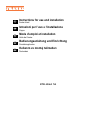
Instructions for use and installation
IT
Istruzioni per l’uso e l’installazione
FR
Mode d’emploi et installation
DE
Bedienungsanleitung und Einrichtung
TR
Kullanım ve montaj talimatları
Cooker Hood
Cappa
Hotte de Cuisine
Dunstabzugshaube
Davlumbaz
FPD 4506 I XS
INDEX
EN
RECOMMENDATIONS AND SUGGESTIONS ..................................................................................................................... 3
CHARACTERISTICS ............................................................................................................................................................. 4
INSTALLATION...................................................................................................................................................................... 6
USE ...................................................................................................................................................................................... 15
MAINTENANCE ................................................................................................................................................................... 17
INDICE
IT
CONSIGLI E SUGGERIMENTI............................................................................................................................................ 19
CARATTERISTICHE............................................................................................................................................................ 20
INSTALLAZIONE ................................................................................................................................................................. 22
USO...................................................................................................................................................................................... 31
MANUTENZIONE ................................................................................................................................................................ 33
SOMMAIRE
FR
CONSEILS ET SUGGESTIONS.......................................................................................................................................... 35
CARACTERISTIQUES......................................................................................................................................................... 36
INSTALLATION.................................................................................................................................................................... 38
UTILISATION ....................................................................................................................................................................... 47
ENTRETIEN......................................................................................................................................................................... 49
INHALTSVERZEICHNIS
DE
EMPFEHLUNGEN UND HINWEISE ................................................................................................................................... 51
CHARAKTERISTIKEN ......................................................................................................................................................... 52
MONTAGE ........................................................................................................................................................................... 54
BEDIENUNG........................................................................................................................................................................ 63
WARTUNG........................................................................................................................................................................... 65
IÇERIKLER
TR
TAVSIYELER VE ÖNERILER.............................................................................................................................................. 67
ÖZELLIKLER........................................................................................................................................................................ 68
MONTAJ............................................................................................................................................................................... 70
KULLANIM ........................................................................................................................................................................... 81
BAKIM .................................................................................................................................................................................. 82
2
2
RECOMMENDATIONS AND SUGGESTIONS
The Instructions for Use apply to several versions of this appliance. Accordingly, you may find descriptions of individual features that do not apply to
your specific appliance.
INSTALLATION
• The manufacturer will not be held liable for any damages resulting from incorrect or improper
installation.
• The minimum safety distance between the cooker top and the extractor
hood is 650 mm (some models can be installed at a lower height, please refer to the paragraphs on working dimensions and installation).
• Check that the mains voltage corresponds to that indicated on the rating plate fixed to the inside of the hood.
• For Class I appliances, check that the domestic power supply guarantees adequate earthing.
Connect the extractor to the exhaust flue through a pipe of minimum diameter 120 mm. The
route of the flue must be as short as possible.
• Do not connect the extractor hood to exhaust ducts carrying combustion fumes (boilers, fireplaces, etc.).
• If the extractor is used in conjunction with non-electrical appliances (e.g. gas burning appliances), a sufficient degree of aeration must be guaranteed in the room in order to prevent the
backflow of exhaust gas. The kitchen must have an opening communicating directly with the
open air in order to guarantee the entry of clean air.
USE
• The extractor hood has been designed exclusively for domestic use to eliminate kitchen
smells.
• Never use the hood for purposes other than for which it has been designed.
• Never leave high naked flames under the hood when it is in operation.
• Adjust the flame intensity to direct it onto the bottom of the pan only, making sure that it does
not engulf the sides.
• Deep fat fryers must be continuously monitored during use: overheated oil can burst into
flames.
• Do not flambè under the range hood; risk of fire
• This appliance is not intended for use by persons (including children) with reduced physical,
sensory or mental capabilities, or lack of experience and knowledge, unless they have been
given supervision or instruction concerning use of the appliance by a person responsible for
their safety.
• Children should be supervised to ensure that they do not play with the appliance.
• “ CAUTION: Accessible parts may become hot when used with cooking appliances”.
MAINTENANCE
• Switch off or unplug the appliance from the mains supply before carrying out any maintenance work.
• Clean and/or replace the Filters after the specified time period (Fire hazard).
• Clean the hood using a damp cloth and a neutral liquid detergent.
The symbol
on the product or on its packaging indicates that this product may not be treated
as household waste. Instead it shall be handed over to the applicable collection point for the recycling of electrical and electronic equipment. By ensuring this product is disposed of correctly,
you will help prevent potential negative consequences for the environment and human health,
which could otherwise be caused by inappropriate waste handling of this product. For more detailed information about recycling of this product, please contact your local city office, your
household waste disposal service or the shop where you purchased the product.
EN
3
3
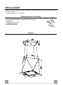
CHARACTERISTICS
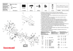
Components
Ref.
1
2
3
4
5
Ref.
11
12h
12c
EN
Q.ty
1
1
1
1
1
Q.ty
4
4
5
Q.ty
1
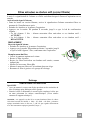
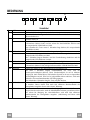
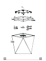
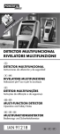
Product Components
Hood Canopy complete with: Controls, Light, Filters, Motor.
Hood support Plate
Power supply cable lock
Cable raceway
Cover for Hood support Plate
Installation Components
Wall plugs ø 10
Screws M5 x 70
Screws 2.9 x 9.5
Documentation
Instruction Manual
4
4
2
5
12c
4
3
12c
11
12h
1
EN
5
5
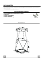
INSTALLATION
This hood is designed to be mounted on the ceiling/on a shelf, above a free-standing Hob (min. 650
mm), in:
• Recirculation version: Internal recirculation.
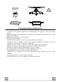
Sequence of operations - Installation
•
•
•
•
•
•
Preparing for installation
Drilling the Ceiling/Shelf and Fixing the support plate
Connections
Fitting the hood body
Functional Check
Disposal of Packaging
Dimensions
EN
6
6
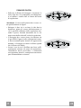
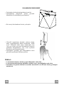
Ceiling/Shelf drilling and Plate Fixing
CEILING/SHELF DRILLING
• Use a plumb-line and mark the centre of the cooking hob on the Support Ceiling/Shelf
• Rest the Plate against the Ceiling/Shelf, making sure it is the right way up, as shown in the
figure.
• Mark the centres of the holes in the plate.
• Drill the following points:
• Ceilings in solid concrete: As per concrete plugs used.
• Ceilings in hollow bricks with 20 mm resistance thickness: Drill a hole ø 10 mm (insert
Plugs 11 supplied immediately).
• Ceilings with Wood Beams: As per Wood Screws used (not supplied).
• Wooden shelf, with a resistant thickness of 15 mm: drill a hole ø 7 mm.
• Feeding the electric supply cable: drill a hole ø 10 mm.
• Insert two screws, crossing them and leaving 4-5 mm from the ceiling:
• for solid concrete, concrete plugs, not provided.
• for hollow bricks with approx. 20 mm resistance thickness, screws 12h, provided.
• for wooden beams, wood screws, not provided.
• for wooden shelves, screws with washers and nuts, not provided.
EN
7
7
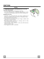
FIXING THE PLATE
• Lift up the Fixing plate and fit the slots onto the
two screws previously inserted in the ceiling, and
turn until they are at the centre of the adjustment
slot.
1
2
1
2
Warning: The plate must be facing in the direction
shown in the figure
• Tighten the two screws completely and screw in
the other two provided; before locking the screws
completely it is possible to make adjustments by
turning the piece, making sure that the screws do
not come out of the adjustment slot.
• The unit must be securely fastened both due to the
weight of the Hood and the stress caused by
occasional sideways pressure on the Appliance
when in position. Once the unit has been fixed,
make sure that the plate is stable.
• In all cases where the Ceiling is not sufficiently
strong at the point of suspension, the Installation
technician must strengthen it with suitable plates
and counterplates, anchored to structurally sound
elements.
EN
8
8
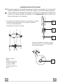
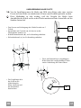
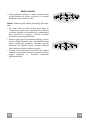
CONNECTING HOOD-PLATE CABLES
N.B. Before proceeding with installation the Hood must be raised to a height of at
least 650 mm above the cooker hob by means of a support or with the assistance
of another person.
This operation is essential, as the Hood Cables are to be connected to the Plate
mounted on the ceiling, and this must be done without the weight of the Hood
bearing down on the structure.
• The system used to fix the 4 Cables comprises 3 components:
• Threaded pawl (a) already mounted on the ceiling Plate.
• Cable locking screw (b), provided.
• Safety knob (c), provided.
a
b
c
• Pass the 4 cables (fastened to the Hood
Canopy) through the respective holes in
the Plate Cover.
• Insert the Cable
raceway
4 in the hole on the
Plate Cover and pass
the Hood power
supply cable
through it.
EN
4
9
9
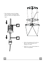
• Pay attention to which side of the Plate
is fixed to the ceiling, final installation
must be as shown in the figure.
B
C
• Insert the safety knobs (c) into the
respective cables, with the thread to the
top.
• Insert the cable locking screws (b) into
the respective cables.
EN
1
10
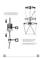
• Pass the Cables into the slots on the threaded pawls (a) and
tighten the cable locking screws (b) into the pawls
themselves.
• When the operation has been
completed, the result should be as
shown in the figure for all 4
cables.
• At this point, all 4 cables are now
connected to the Plate.
Tension the Cables by pushing them
upwards, so that they slide inside the
cable locking screw and out through the
slot in the threaded pawl.
This is possible because the cable
locking screw involves a system that
allows the Cable to slide in one direction
only, preventing it from sliding in the
other direction.
Make sure that the Cables are all the
same length, to facilitate final levelling
operations.
EN
1
11
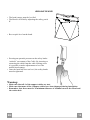
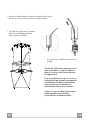
LEVELLING THE HOOD
• The hood canopy must be levelled.
• The Hood is levelled by adjusting the safety pawls
C.
• Rest a spirit level on the hood.
• Exerting an upwards pressure on the safety knobs
“unlocks” movement of the Cable. By inserting or
extracting the cable from the cable locking screw
it is possible to make adjustments to level the
mobile hood canopy.
• Once the hood has been set level, the safety knobs
must be tightened.
Warning:
• Make sure that all 4 of the support cables are taut.
• Make sure that none of the 4 support cables have been damaged during installation.
• Remember that there must be a minimum distance of 650mm between the Hood and
the cooker hob.
EN
1
12
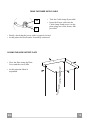
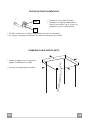
FIXING THE POWER SUPPLY CABLE
12c
3
• Take the Cable clamp 3 provided.
• Insert the Power cable into the
Cable clamp 3 and screw it to the
plate using one of the Screws 12c
provided.
• Finally, check that the power cable is properly locked.
• At this point, the Hood can be electrically connected.
CLOSING THE HOOD SUPPORT PLATE
• Close the Plate using the Plate
Cover and the screws 12c.
• At this point the Hood is
suspended.
EN
1
13
ELECTRICAL CONNECTION
• Connect the hood to the mains through a two-pole switch having a contact gap of at least 3 mm.
• Remove the grease filters (see paragraph Maintenance) being
sure that the connector of the feeding cable is correctly inserted
in the socket placed on the side of the fan.
Warning! Electrical connection must be carried out by a certified, approved electrician. Always comply with the regu‐
lations imposed by the relevant electrical safety authorities and with those indicated by the power supply company. When connecting the appliance it is essential that it be properly earthed. EN
1
14
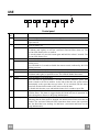
USE
S1
L
T1
T2
T3
T4
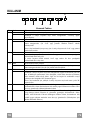
Control panel
Butt Led
on
L T1
-
T2
Fixed
T3
Fixed
T4
Fixed
S1
Fixed
Flashing
EN
Function
Turns the lights ON/OFF at maximum strength.
Press and hold the button for approximately 2 seconds to turn the Courtesy
Lights On/Off.
Turns the Motor off.
Press and hold the button for approximately 5 seconds, with all the loads turned
off (Motor and Lights), to turn the Activated Charcoal Filter alarm on. The
relevant LED flashes twice to confirm.
To turn the alarm off, press the button again and hold for at least 5 seconds. The
relevant LED flashes once.
Turns the motor on at speed one.
Press and hold for 5 seconds to enable the remote control, indicated by the LED
flashing twice.
Press and hold for 5 seconds to disable the remote control, indicated by the LED
flashing just once.
Turns the Motor on at speed two.
Press and hold the button for approximately 5 seconds, with all the loads turned
off (Motor and Lights), to perform a reset. The LED S1 flashes three times.
Turns the Motor on at speed three.
Press and hold for approximately 2 seconds to activate Intensive speed. This
speed is timed to run for 10 minutes. At the end of this time, the system returns
automatically to the speed that was set before. If it is activated with the motor
turned off, the hood will switch to OFF at the end of the time.
To disable this function, press and hold the button for 2 seconds or press T1.
Signals the Metal Grease Filter saturation alarm, indicating that it is necessary to
wash the filters. The alarm is triggered after the Hood has been in operation for
100 working hours. (Reset see the parag. Maintenance)
When this is activated, it signals the Activated Charcoal Filter saturation alarm,
indicating that the filter must be changed; the Metal Grease Filters must also be
washed. The Activated Charcoal Filter saturation alarm comes into operation
after the Hood has been working for 200 hours. (Activation and Reset see the
parag. Maintenance)
1
15
REMOTE CONTROL
The appliance can be controlled using a remote control powered
by a 1.5 V carbon-zinc alkaline batteries of the standard LR03AAA type (not included).
• Do not place the remote control near to heat sources.
• Used batteries must be disposed of in the proper manner.
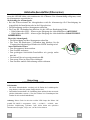
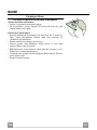
Cleaning the Comfort Panels
• Pull the Comfort Panel to open it.
• Disconnect the panel from the hood canopy by sliding the fixing pin lever.
• The comfort panel must never be washed in a dishwasher.
• Clean the outside by using a damp cloth and neutral liquid detergent.
• Clean the inside as well by using a damp cloth and neutral detergent; do not use wet cloths or sponges, or jets of water; do
not use abrasive substances.
• When the above operation has been completed, hook the panel
back to the hood canopy and close it by turning the knob in the
opposite direction.
EN
1
16
MAINTENANCE
Grease filters
CLEANING THE SELF-BEARING METAL GREASE FILTERS
Resetting the alarm signal
• Turn the Lights and the Suction Motor off.
• Press T3 and hold for at least 5 seconds, until LED F flashes
three times in confirmation.
Cleaning the Filters
• These filters can be washed in a dishwasher, and require
cleaning approximately once every 2 months or more
frequently in the case of particularly intensive use.
• Open the Suction panel by pulling it.
• Remove the Filter, pushing it towards the back of the unit and
at the same time pulling downward.
• Wash the Filter without bending it, and leave it to dry
completely before replacing.
• Replace, taking care to ensure that the handle faces forwards.
• Close the Suction panel.
EN
1
17
Activated Charcoal Filter (Recirculation Version)
This cannot be washed or regenerated, and must be changed when led S1 starts to flash, or at
least once every 4 months. The alarm signal only appears when the Suction motor is turned on.
Activating the alarm signal
• In Recirculation Version Hoods, the Filter Saturation Alarm must be activated on
installation or at a later date.
• Turn the Lights and the Suction Motor off.
• Press button T1 and hold it for 5 seconds until the LED flashes in confirmation:
• Led flashes twice – Activated Charcoal Filter saturation alarm ACTIVATED.
• Led flashes once – Activated Charcoal Filter saturation alarm DEACTIVATED.
CHANGING
Resetting the alarm signal
• Turn the Lights and the Suction Motor off.
• Press T3 and hold for at least 5 seconds, until LED F flashes
three times in confirmation.
Changing the Filter
• Open the Suction panel by pulling it.
B
A
• Remove the Grease Filter
• Remove the saturated activated charcoal filter as shown (A).
• Fit the new filters (B).
• Fit the new Filter, hooking it into place.
• Fit the Grease filter and the Light Unit back into place.
Lighting unit
REPLACING OF THE LED UNIT
LED
• To remove the lighting unit a screwdriver can be used in order to
slightly press the side part of the unit.
• Remove the unit, remove the electrical connector and replace the unit
with a new one. ("To purchase contact technical support")
Warning: This appliance is fitted with a white LED lamp classed as 1M
according to EN 60825-1: 1994 + A1:2002 + A2:2001 standards; maximum optical power emitted @439nm: 7µW. Do not look directly at the
light through optical devices (binoculars, magnifying glasses…).
EN
1
18
CONSIGLI E SUGGERIMENTI
Questo libretto di istruzioni per l'uso è previsto per più versioni dell' apparecchio.
É possibile che siano descritti singoli particolari della dotazione, che non riguardano il Vostro apparecchio.
INSTALLAZIONE
• Il produttore declina qualsiasi responsabilità per danni dovuti ad installazione non corretta o non conforme alle regole dell’arte.
• La distanza minima di sicurezza tra il Piano di cottura e la Cappa deve essere di 650
mm, (alcuni modelli possono essere installati ad un’altezza inferiore, fare riferimento ai
paragrafi ingombro e installazione).
• Verificare che la tensione di rete corrisponda a quella riportata nella targhetta posta
all’interno della Cappa.
• Per Apparecchi in Classe Ia accertarsi che l’impianto elettrico domestico garantisca un
corretto scarico a terra.
• Collegare la Cappa all’uscita dell’aria aspirata con tubazione di diametro pari o superiore a 120 mm. Il percorso della tubazione deve essere il più breve possibile.
• Non collegare la Cappa a condotti di scarico dei fumi prodotti da combustione (caldaie,
caminetti, ecc.).
• Nel caso in cui nella stanza vengano utilizzati sia la Cappa che apparecchi non azionati
da energia elettrica (ad esempio apparecchi utilizzatori di gas), si deve provvedere ad
una aerazione sufficiente dell’ambiente. Se la cucina ne fosse sprovvista, praticare
un’apertura che comunichi con l’esterno, per garantire il richiamo d’aria pulita.
USO
• La Cappa è stata progettata esclusivamente per uso domestico, per abbattere gli odori
della cucina.
• Non fare mai uso improprio della Cappa.
• Non lasciare fiamme libere a forte intensità sotto la Cappa in funzione.
• Regolare sempre le fiamme in modo da evitare una evidente fuoriuscita laterale delle
stesse rispetto al fondo delle pentole.
• Controllare le friggitrici durante l’uso: l’olio surriscaldato potrebbe infiammarsi.
• Non preparare alimenti flambè sotto la cappa da cucina; pericolo d'incendio.
• Questo apparecchio non deve essere utilizzato da persone (bambini inclusi) con ridotte
capacità psichiche, sensoriali o mentali, oppure da persone senza esperienza e conoscenza, a meno che non siano controllati o istruiti all’uso dell’apparecchio da persone
responsabili della loro sicurezza.
• I bambini devono essere supervisionati per assicurarsi che non giochino con
l’apparecchio.
• “ATTENZIONE: Le parti accessibili possono diventare molto calde se utilizzate con degli apparecchi di cottura”.
MANUTENZIONE
• Prima di procedere a qualsiasi operazione di manutenzione, disinserire la Cappa togliendo la spina elettrica o spegnendo l’interruttore generale.
• Effettuare una scrupolosa e tempestiva manutenzione dei Filtri secondo gli intervalli
consigliati (Rischio di incendio).
• Per la pulizia delle superfici della Cappa è sufficiente utilizzare un panno umido e detersivo liquido neutro.
Il simbolo
sul prodotto o sulla confezione indica che il prodotto non deve essere considerato
come un normale rifiuto domestico, ma deve essere portato nel punto di raccolta appropriato per
il riciclaggio di apparecchiature elettriche ed elettroniche. Provvedendo a smaltire questo prodotto in modo appropriato, si contribuisce a evitare potenziali conseguenze negative per l’ambiente
e per la salute, che potrebbero derivare da uno smaltimento inadeguato del prodotto. Per informazioni più dettagliate sul riciclaggio di questo prodotto, contattare l’ufficio comunale, il servizio
locale di smaltimento rifiuti o il negozio in cui è stato acquistato il prodotto.
IT
1
19
CARATTERISTICHE
Componenti
Rif.
1
2
3
4
5
Rif.
11
12h
12c
IT
Q.tà
1
1
1
1
1
Q.tà
4
4
5
Q.tà
1
Componenti di Prodotto
Corpo Cappa completo di: Comandi, Luce, Filtri, Motore.
Piastra supporto Cappa
Bloccacavo alimentazione
Passacavo
Coperchio Piastra supporto Cappa
Componenti di Installazione
Tasselli ø 10
Viti M5 x 70
Viti 2,9 x 9,5
Documentazione
Libretto Istruzioni
2
20
2
5
12c
4
3
12c
11
12h
1
IT
2
21
INSTALLAZIONE
Questa Cappa è predisposta per essere installata a Soffitto/Mensola, sopra (650 mm min.) un Piano
di Cottura a isola in:
• Versione Filtrante: Ricircolo interno.
Sequenza operazioni Installazione
•
•
•
•
•
•
Preparazione all’Installazione
Foratura Soffitto/Mensola e Fissaggio Piastra di sostegno
Connessioni
Montaggio Corpo Cappa
Controllo Funzionale
Smaltimento Imballi
Ingombro
IT
2
22
Foratura Soffitto/Mensola e Fissaggio Piastra
FORATURA SOFFITTO/MENSOLA
• Con l’ausilio di un Filo a piombo riportare sul Soffitto/Mensola di supporto il centro del
Piano Cottura.
• Appoggiare al Soffitto/Mensola la Piastra facendo attenzione a posizionarla nel verso giusto,
come indicato in figura.
• Segnare i centri dei Fori della Piastra.
• Forare i punti seguenti:
• Soffitto in Calcestruzzo massiccio: secondo Tasselli per Calcestruzzo impiegati.
• Soffitto in Laterizio a camera d’aria, con spessore resistente di 20 mm: Forare ø 10 mm
(inserire subito i Tasselli 11 in dotazione).
• Soffitto in Travatura di Legno: secondo Viti per Legno impiegate (non fornite).
• Mensola in Legno, con spessore resistente di 15 mm: forare ø 7 mm.
• Passaggio del Cavo elettrico di Alimentazione: forare ø 10 mm.
• Avvitare, incrociandole e lasciando 4-5 mm dal soffitto, due viti:
• per Calcestruzzo massiccio, Tasselli per Calcestruzzo, non in dotazione.
• per Laterizio a camera d’aria, con spessore resistente di 20 mm circa, Viti 12h, in dotazione.
• per Travatura di legno, Viti per legno, non in dotazione.
• per Mensola di legno, Viti con Rondelle e Dadi non in dotazione.
IT
2
23
FISSAGGIO PIASTRA
• Sollevare la Piastra di fissaggio e incastrare le
asole sulle due viti predisposte precedentemente al soffitto e ruotare fino al centro dell’asola
di regolazione.
1
2
1
2
Attenzione: Il verso della piastra deve essere come quello indicato in figura
• Stringere le due viti e avvitare le altre due in
dotazione; prima di serrare definitivamente le
viti è possibile effettuare delle regolazioni ruotando il pezzo, facendo attenzione che le viti
non escano dalla sede dell’asola di regolazione.
• Il fissaggio deve essere sicuro in relazione sia
al peso della Cappa sia alle sollecitazioni causate da occasionali spinte laterali all’Apparecchio
montato. A fissaggio avvenuto verificare quindi
che la Piastra sia stabile.
• In tutti i casi in cui il Soffitto non fosse sufficientemente robusto sul punto di sospensione,
l’Installatore dovrà provvedere a irrobustirlo
con opportune piastre e contropiastre ancorate a
parti strutturalmente resistenti.
IT
2
24
COLLEGAMENTO CAVI CAPPA-PIASTRA
N.B. Prima di proseguire con l’Installazione è necessario portare la Cappa all’altezza
di almeno 650 mm dal piano di cottura con un supporto o con l’aiuto di una seconda persona.
Questo accorgimento è fondamentale in quanto andremo a collegare i Cavi della
Cappa alla Piastra montata sul soffitto necessariamente senza avere il peso della Cappa che gravi sulla struttura.
• Il sistema di fissaggio dei 4 Cavi è formato da 3 parti:
• Nottolino filettato (a) già montato sulla Piastra a soffitto.
• Vite bloccacavo (b) in dotazione.
• Pomello di sicurezza (c) in dotazione.
a
b
c
• Passare i 4 cavi (agganciati al Corpo
Cappa) nei rispettivi fori del Coperchio
Piastra.
• Inserire il Passacavo
4 nel foro sul Coperchio Piastra e
passarci il Cavo alimentazione della
Cappa.
IT
4
2
25
• Fare attenzione al verso della Piastra
fissata al soffitto, l’istallazione finale
deve essere come indicato in figura.
B
C
• Infilare i pomelli di sicurezza (c) nei rispettivi cavi con la filettatura verso
l’alto.
• Infilare le Viti bloccacavo (b) nei rispettivi cavi.
IT
2
26
• Passare i Cavi nelle asole dei Nottolini filettati (a) ed avvitare le Viti bloccacavo (b) ai Nottolini stessi.
• Ad operazione terminata il risultato deve essere come indicato in
figura per tutti e 4 i Cavi.
• Arrivati a questo punto abbiamo tutti e
4 i Cavi collegati alla Piastra.
Portare in tensione i Cavi spingendoli
verso l’alto in modo che scorrano dentro
la Vite bloccacavo e fuori dall’asola del
Nottolino filettato.
Questo è possibile perché la Vite bloccacavo ha un sistema che permette lo scorrimento del Cavo al suo interno in un
solo verso bloccando lo scorrimento nel
verso contrario.
Fare attenzione che i Cavi abbiano tutti
la stessa lunghezza per agevolare
l’operazione di livellamento finale.
IT
2
27
LIVELLAMENTO DELLA CAPPA
• E’ necessario effettuare il livellamento del corpo
cappa.
• Il livellamento della Cappa viene effettuato agendo sui Nottolini di sicurezza C.
• Appoggiare una livella sulla cappa.
• Esercitando una pressione, verso l’alto, sui Pomelli di sicurezza si “sblocca” il movimento del Cavo.
Inserendo od estraendo il cavo dalla vite Bloccacavo è possibile effettuare le registrazioni che
permettono il livellamento del corpo mobile della
cappa.
• Una volta livellata a misura la Cappa, andremo a
stringere i pomelli di sicurezza.
Attenzione:
• Accertarsi che tutti e 4 i Cavi di sostegno siano in tensione.
• Accertarsi che tutti e 4 i Cavi di sostegno non abbiano subito danni durante
l’installazione.
• Va ricordato che la distanza minima trà la Cappa e il piano di cottura della cucina deve essere di 650mm.
IT
2
28
FISSAGGIO DEL CAVO ALIMENTAZIONE
12c
3
• Prendere il Bloccacavo 3 in dotazione.
• Infilare il Cavo alimentazione nel
Bloccacavo 3 e avvitarlo alla piastra
con una Vite 12c in dotazione.
• Verificare infine che il cavo di alimentazione sia bloccato correttamente.
• A questo punto è possibile effettuare il collegamento elettrico della Cappa.
CHIUSURA PIASTRA SUPPORTO CAPPA
• Chiudere la Piastra con il Coperchio Piastra usando le Viti 12c.
• A questo punto la Cappa è appesa.
IT
2
29
CONNESSIONE ELETTRICA
• Collegare la Cappa all’Alimentazione di Rete interponendo un
Interruttore bipolare con apertura dei contatti di almeno 3 mm.
• Rimuovere i Filtri antigrasso (vedi par. “Manutenzione”) e assicurarsi che il connettore del Cavo di alimentazione sia correttamente inserito nella presa dell’Aspiratore
Attenzione! Il collegamento elettrico deve essere fatto da un installatore‐elettricista certificato ed autorizzato. Vanno rispettate le normative delle autorità competenti in materia di sicurezza elettrica e quelle dell’ente locale erogatore dell’energia elettrica. Nell’effettuare il collegamento deve assolutamente essere realizzata la messa a terra dell’apparecchio. IT
3
30
USO
S1
L
T1
T2
T3
T4
Quadro comandi
Tasto Led
L T1 -
T2
Fisso
T3
Fisso
T4
Fisso
S1
Fisso
Lampeggiante
IT
Funzione
Accende/Spegne le luci alla massima luminosità.
Tenendo premuto il tasto per circa 2 secondi Accende/Spegne le Luci di Cortesia.
Spegne il motore.
Tenendo il tasto premuto per circa 5 secondi, quando tutti i carichi sono spenti
(Motore+Luce), si attiva l’allarme dei Filtri al Carbone attivo visualizzando un
doppio lampeggio del relativo Led.
Per disattivarlo, si preme di nuovo il tasto per altri 5 secondi visualizzando un
lampeggio singolo del relativo Led.
Accende il motore alla prima velocità.
Tenendo premuto per 5 secondi si abilità il telecomando visualizzando un doppio
lampeggio del medesimo led.
Tenendo il tasto premuto per 5 secondi si disabilita il telecomando visualizzando
il lampeggio del rispettivo led una sola volta.
Accende il motore alla seconda velocità.
Tenendo premuto il tasto per circa 5 secondi, quando tutti i carichi sono spenti
(Motore+Luce), si effettua il reset visualizzando il triplo lampeggio del Led S1.
Accende il motore alla terza velocità.
Tenendo premuto il tasto per circa 2 secondi attiva la velocità Intensiva. Questa
velocità è temporizzata a 10 minuti. Terminato il tempo, il sistema ritorna automaticamente alla velocità precedentemente selezionata. Se attivata da motore
spento una volta finito il tempo passa alla modalità OFF.
Per disattivarlo tenere il tasto premuto per 2 secondi o premere T1.
Segnala l’allarme saturazione Filtri Antigrasso Metallici e la necessità di lavarli.
L’allarme entra in funzione dopo 100 ore di lavoro effettivo della Cappa. (Reset
vedi parag. Manutenzione)
Segnala, quando è attivato, l’allarme saturazione Filtro Antiodore al Carbone
Attivo, che deve essere sostituito; devono anche essere lavati i Filtri Antigrasso
Metallici. L’allarme saturazione Filtro Antiodore al Carbone Attivo entra in funzione dopo 200 ore di lavoro effettivo della Cappa. (Attivazione e Reset vedi
parag. Manutenzione)
3
31
TELECOMANDO
Questo apparecchio può essere comandato per mezzo di un telecomando, alimentato con pile alcaline zinco-carbone da 1,5 V del
tipo standard LR03-AAA (non incluse).
• Non riporre il telecomando in prossimità di fonti di calore.
• Non disperdere le pile nell’ambiente, depositarle negli appositi
contenitori.
Pulizia dei Comfort Panel
• Aprire il Comfort Panel tirandolo.
• Sganciare il pannello dal corpo cappa facendo scorrere
l’apposita leva del perno di fissaggio.
• Il comfort panel non va assolutamente lavato in lavastoviglie.
• Pulirlo esternamente con un panno umido e detersivo liquido
neutro.
• Pulirlo anche internamente utilizzando un panno umido e detergente neutro; non utilizzare panni o spugne bagnate, né getti
d’acqua; non utilizzare sostanze abrasive.
• Ad operazione ultimata riagganciare il pannello al corpo cappa
e richiuderlo.
.
IT
3
32
MANUTENZIONE
Filtri antigrasso
PULIZIA FILTRI ANTIGRASSO METALLICI AUTOPORTANTI
Reset del segnale di allarme
• Spegnere le Luci e il Motore di aspirazione.
• Premere il tasto T3 per almeno 5 secondi, sino al triplo lampeggio di conferma del led F.
Pulizia Filtri
• Sono lavabili anche in lavastoviglie, e necessitano di essere
lavati ogni 2 mesi circa di utilizzo o più frequentemente, per un
uso particolarmente intenso.
• Aprire il Pannello Aspirante tirandolo.
• Togliere il Filtro spingendolo verso la parte posteriore del
gruppo e tirando contemporaneamente verso il basso.
• Lavare il Filtro evitando di piegarlo, e lasciarlo asciugare prima di rimontarlo.
• Rimontarlo facendo attenzione a mantenere la maniglia verso
la parte visibile esterna.
• Richiudere il Pannello Aspirante.
IT
3
33
Filtri antiodore al Carbone attivo (Versione Filtrante)
Non è lavabile e non è rigenerabile, va sostituito quando il led S1 lampeggia o almeno ogni 4
mesi. La segnalazione di allarme si verifica solo quando é azionato il Motore di aspirazione.
Attivazione del segnale di allarme
• Nelle Cappe in Versione Filtrante, la segnalazione di Allarme saturazione Filtri va attivata al
momento dell’installazione o successivamente.
• Spegnere le Luci e il Motore di aspirazione.
• Premere il Tasto T1 per 5 secondi sino al lampeggio di conferma del Led:
• 2 lampeggi Led - Allarme saturazione Filtro antiodore al Carbone attivo ATTIVATO.
• 1 lampeggio Led - Allarme saturazione Filtro antiodore al Carbone attivo DISATTIVATO.
SOSTITUZIONE
Reset del segnale di allarme
• Spegnere le Luci e il Motore di aspirazione.
• Premere il tasto T3 per almeno 5 secondi, sino al triplo lampeggio di conferma del led F.
Sostituzione Filtro
• Aprire il Pannello Aspirante tirandolo.
• Rimuovere il Filtro antigrasso
• Rimuovere i Filtri antiodore al Carbone attivo saturi, come indicato (A).
• Montare i nuovi Filtri, come indicato (B).
• Montare il nuovo Filtro agganciandolo nella sua sede.
• Rimontare il Filtro antigrasso e il gruppo illuminazione.
B
A
Illuminazione
SOSTITUZIONE LAMPADE
Faretto Led
• Con l’aiuto di un cacciavite, fare una leggera pressione sulle estremità
del blocco illuminazione per sbloccare tutto il gruppo.
• Estrarlo, scollegare la connessione e sostituirlo con uno di uguali caratteristiche. ("Per l'acquisto rivolgersi all'assistenza tecnica").
Attenzione: Questo apparecchio è provvisto di una luce LED bianca di
classe 1M secondo la norma EN 60825-1: 1994 + A1:2002 + A2:2001;
massima potenza ottica emessa@439nm: 7µW. Non osservare direttamente con strumenti ottici (binocolo, lente d’ingrandimento….).
IT
3
34
CONSEILS ET SUGGESTIONS
La présente notice d'emploi vaut pour plusieurs versions de l'appareil. Elle peut contenir des descriptions d'accessoires ne figurant pas dans votre appareil.
INSTALLATION
• Le fabricant décline toute responsabilité en cas de dommage dû à une installation non
correcte ou non conforme aux règles de l’art.
• La distance minimale de sécurité entre le plan de cuisson et la hotte doit être de 650
mm au moins (certains modèles peuvent être installés à une hauteur inférieure : se reporter aux paragraphes « Encombrement » et « Installation »).
• Vérifier que la tension du secteur correspond à la valeur qui figure sur la plaquette
apposée à l’intérieur de la hotte.
• Pour les Appareils appartenant à la Ière Classe, veiller à ce que la mise à la terre de
l’installation électrique domestique ait été effectuée conformément aux normes en vigueur.
• Connecter la hotte à la sortie d’air aspiré à l’aide d’une tuyauterie d’un diamètre égal ou
supérieur à 120 mm. Le parcours de la tuyauterie doit être le plus court possible.
• Ne pas connecter la hotte à des conduites d’évacuation de fumées issues d’une combustion tel que (Chaudière, cheminée, etc…).
• Si vous utilisez des appareils qui ne fonctionnent pas à l’électricité dans la pièce ou est
installée la hotte (par exemple: des appareils fonctionnant au gaz), vous devez prévoir
une aération suffisante du milieu. Si la cuisine en est dépourvue, pratiquez une ouverture qui communique avec l’extérieur pour garantir l’infiltration de l’air pur.
UTILISATION
• La hotte a été conçue exclusivement pour l’usage domestique, dans le but d’éliminer
les odeurs de la cuisine.
• Ne jamais utiliser abusivement la hotte.
• Ne pas laisser les flammes libres à forte intensité quand la hotte est en service.
• Toujours régler les flammes de manière à éviter toute sortie latérale de ces dernières
par rapport au fond des marmites.
• Contrôler les friteuses lors de l’utilisation car l’huile surchauffée pourrait s’enflammer.
• Ne pas préparer d’aliments flambés sous la hotte de cuisine : risque d’incendie
• Cet appareil ne doit pas être utilisé par des personnes (y compris les enfants) ayant
des capacités psychiques, sensorielles ou mentales réduites, ni par des personnes
n’ayant pas l’expérience et la connaissance de ce type d’appareils, à moins d'être sous
le contrôle et la formation de personnes responsables de leur sécurité.
• Les enfants doivent être surveillés pour s'assurer qu'ils ne jouent pas avec l'appareil.
• « ATTENTION : Les parties accessibles peuvent devenir très chaudes si utilisées avec
des appareils de cuisson. »
ENTRETIEN
• Avant de procéder à toute opération d’entretien, retirer la hotte en retirant la fiche ou en
actionnant l’interrupteur général.
• Effectuer un entretien scrupuleux et en temps dû des Filtres, à la cadence conseillée
(Risque d’incendie).
• Pour le nettoyage des surfaces de la hotte, il suffit d’utiliser un chiffon humide et détersif liquide neutre.
Le symbole
sur le produit ou son emballage indique que ce produit ne peut être traité comme
déchet ménager. Il doit plutôt être remis au point de ramassage concerné, se chargeant du recyclage du matériel électrique et électronique. En vous assurant que ce produit est éliminé correctement, vous favorisez la prévention des conséquences négatives pour l’environnement et la santé
humaine qui, sinon, seraient le résultat d’un traitement inapproprié des déchets de ce produit. Pour
obtenir plus de détails sur le recyclage de ce produit, veuillez prendre contact avec le bureau municipal de votre région, votre service d’élimination des déchets ménagers ou le magasin où vous avez
acheté le produit.
FR
3
35
CARACTERISTIQUES
Composants
Réf.
1
2
3
4
5
Réf.
11
12h
12c
FR
Q.té
1
1
1
1
1
Q.té
4
4
5
Q.té
1
Composants du produit
Corps hotte équipé de : Commandes, lumière, filtres, moteur.
Plaque support hotte
Serre-câble alimentation
Passe-câble
Couvrir pour Plaque support hotte
Composants de l’installation
Chevilles ø 10
Vis M5 x 70
Vis 2,9 x 9,5
Documentation
Manuel d’instructions
3
36
2
5
12c
4
3
12c
11
12h
1
FR
3
37
INSTALLATION
Cette hotte est prévue pour être installée au plafond/étagère, au-dessus (650 mm min.) d’un plan de
cuisson en îlot en :
• Version filtrante Recirculation intérieure.
Séquence opérations d’installation
•
•
•
•
•
•
Préparation à l’installation
Perçage plafond/étagère et fixation plaque de support
Connexions
Montage du corps de hotte
Contrôle fonctionnel
Élimination des emballages
Encombrement
FR
3
38
Perçage plafond/étagère et fixation plaque
PERÇAGE PLAFOND/ÉTAGÈRE
• À l’aide d’un fil à plomb, ramener sur le plafond/étagère de support le centre du plan de
cuisson.
• Appuyer la plaque au plafond/étagère en veillant de la positionner dans le bon sens, comme
indiqué dans la figure.
• Marquer les centres des trous de la plaque.
• Percer les points suivants :
• Plafond en béton massif : selon les chevilles pour béton employées.
• Plafond en béton et chambre à air, avec une épaisseur résistante de 20 mm : percer ø 10
mm (insérer tout de suite les chevilles 11 fournies).
• Plafond en poutres de bois : selon les vis pour bois employées (non fournies).
• Étagère en bois, avec une épaisseur résistante de 15 mm : percer ø 7 mm.
• Passage du câble électrique d’alimentation : percer ø 10 mm.
• Serrer en diagonale et en laissant 4-5 mm du plafond les deux vis :
• pour béton massif, les chevilles pour béton, non fournies.
• pour béton avec chambre à air, avec une épaisseur résistante d’environ 20 mm, vis 12h
fournies.
• pour poutres de bois, vis pour bois, non fournies.
• pour étagère de bois, vis avec rondelles et écrous non fournies.
FR
3
39
FIXATION PLAQUE
• Soulever la plaque de fixation, emboîter les trous sur
les deux vis précédemment prévues au plafond et
tourner jusqu’au centre du trou de réglage.
1
2
1
2
Attention : Le sens de la plaque doit être celui indiqué
dans la figure.
• Serrer les deux vis et visser les deux autres fournies ;
avant de serrer définitivement les vis vous pouvez
effectuer des réglages en tournant la pièce, en faisant
attention à ce que les vis ne sortent pas du siège du
trou de réglage.
• La fixation doit être sûre aussi bien par rapport au
poids de la hotte qu’aux contraintes provoquées par
des poussées occasionnelles latérales à l’appareil
monté. À la fin de la fixation, vérifier que la plaque
est stable.
• Au cas où le plafond ne serait pas suffisamment
robuste sur le point de suspension, l’installateur
devra le renforcer à l’aide de plaques et de contreplaques opportunes ancrées sur des parties
structurellement résistantes.
FR
4
40
CONNEXION CÂBLES HOTTE-PLAQUE
N.B. Avant de continuer l’installation, amener la hotte à une hauteur d’au moins 650
mm de la plaque de cuisson, à l’aide d’un support ou d’une deuxième personne.
Cette mesure est absolument nécessaire, car lors de la connexion des câbles de
la hotte à la plaque montée au plafond, il est indispensable que le poids de la
hotte ne pèse pas sur la structure.
• Le système de fixation des 4 câbles est constitué de 3 parties :
• Cliquet fileté (a) déjà monté sur la plaque au plafond.
• Vis serre-câble (b) fournie.
• Pommeau de sécurité (c) fourni.
a
b
c
• Passer les 4 câbles (accrochés au corps
de hotte) dans les trous correspondants
du couvercle plaque.
• Insérer le passecâble
4 dans le trou sur le
couvercle plaque et
y passer le câble
d’alimentation de la
hotte.
FR
4
4
41
• Faire attention au sens de la plaque
fixée au plafond, l’installation finale
doit être comme celle indiquée dans la
figure.
B
C
• Insérer les pommeaux de sécurité (c)
dans les câbles respectifs avec le
filetage vers le haut.
• Enfiler les vis serre-câble (b) dans les
câbles correspondants.
FR
4
42
• Passer les câbles dans les trous des cliquets filetés (a) et
serrer les vis serre-câble (b) à ces mêmes cliquets.
• À la fin de l’opération, le résultat
doit être celui indiqué dans la
figure pour les 4 câbles.
• À ce point, les 4 câbles sont reliés à la
plaque.
Tendre les câbles en les poussant vers le
haut de manière à ce qu’ils coulissent
dans la vis serre-câble et hors du trou
du cliquet fileté.
Cela est possible parce que la vis serrecâble possède un système permettant le
coulissement du câble à son intérieur
dans un seul sens, en bloquant le
coulissement dans le sens contraire.
Veiller à ce que les câbles aient tous la
même longueur, pour faciliter
l’opération de nivellement finale.
FR
4
43
NIVELLEMENT DE LA HOTTE
• Il est nécessaire d’effectuer le nivellement du
corps de hotte.
• Le nivellement de la hotte s’effectue en
intervenant sur les cliquets de sécurité C.
• Appuyer un niveau sur la hotte.
• Pour débloquer le mouvement du câble, pousser
vers le haut les pommeaux de sécurité. Insérer ou
extraire le câble de la vis serre-câble pour
effectuer les réglages qui permettent le
nivellement du corps mobile de la hotte.
• Après avoir nivelé la hotte à la mesure nécessaire,
serrer les pommeaux de sécurité.
Attention :
• S’assurer que les 4 câbles de soutien sont en tension.
• S’assurer que les 4 câbles de soutien n’ont pas été endommagés durant l’installation.
• N’oubliez pas que la distance minimum entre la hotte et le plan de cuisson de la cuisine
doit être de 650 mm.
FR
4
44
FIXATION DU CÂBLE D’ALIMENTATION
12c
• Prendre le serre-câble 3 fourni.
• Introduire le câble d’alimentation
dans le serre-câble 3 et le visser à la
plaque avec une vis 12c fournie.
3
• Vérifier ensuite que le câble d’alimentation est serré correctement.
• À ce point, vous pouvez effectuer la connexion électrique de la hotte.
FERMETURE PLAQUE SUPPORT HOTTE
• Fermer la plaque avec le couvercle
plaque en utilisant les vis 12c.
• La hotte est maintenant accrochée.
FR
4
45
BRANCHEMENT ELECTRIQUE
• Brancher la hotte sur le secteur en interposant un interrupteur
bipolaire avec ouverture des contacts d’au moins 3 mm.
• Enlever les filtres à graisse (voir § "Entretien") et s'assurer que
le connecteur du câble d'alimentation soit bien branché dans la
prise du diffuseur.
Attention ! La connexion électrique doit être réalisée par un installateur‐électricien certifié et autorisé. Respecter les normes des autorités compétentes en matière de sécurité électrique et celles du fournisseur local d’électricité. Lors de la réalisation de la connexion, la mise à la terre de l'appareil est impérativement obligatoire. FR
4
46
UTILISATION
S1
L
T1
T2
T3
T4
Tableau des commandes
Touch Led
e
L T1
-
T2
Fixe
T3
Fixe
T4
Fixe
S1
Fixe
Clignotante
FR
Fonction
Allume/Éteint les lumières à la luminosité maximum.
Garder la touche appuyée pendant environ 2 secondes pour Allumer/Éteindre les
lumières de courtoisie.
Éteindre le moteur.
Garder la touche appuyée pendant environ 5 secondes, lorsque toutes les charges
sont éteintes (Moteur+ Éclairage), l’alarme des filtres au charbon actif
s’enclenche et la led correspondante clignotera 2 fois.
Pour la désactiver, appuyer de nouveau sur la touche pendant 5 secondes. La led
correspondante clignotera 1 fois.
Démarre le moteur à la première vitesse.
Garder la touche appuyée pendant environ 5 secondes pour valider la
télécommande. La led correspondante clignotera 2 fois.
Garder la touche appuyée pendant 5 secondes pour invalider la télécommande.
La led correspondante clignotera 1 seule fois
Démarre le moteur à la deuxième vitesse.
Garder la touche appuyée pendant environ 5 secondes, lorsque toutes les charges
sont éteintes (Moteur+ Éclairage), le reset est effectué et la led S1 clignotera 3
fois.
Démarre le moteur à la troisième vitesse.
Garder la touche appuyée pendant environ 2 secondes pour activer la vitesse
intensive. Cette vitesse est temporisée à 10 minutes. Après ce délai, le système
retourne automatiquement à la vitesse précédemment sélectionnée. Si activée
avec le moteur à l’arrêt, à la fin du délai le système passe en mode OFF.
Pour la désactiver, garder l’appui sur la touche pendant 2 secondes ou appuyer
sur T1.
Signale l’alarme saturation filtres à graisse métalliques et la nécessité de les laver.
L’alarme entre en fonction après 100 heures de travail effectif de la hotte. (Reset
voir paragraphe Entretien)
Lorsque l’alarme de saturation du filtre anti-odeur est activée, c’est l’indice que
le filtre doit être remplacé. Laver aussi les filtres à graisse métalliques. L’alarme
de saturation filtre anti-odeur au charbon actif entre en fonction après 200 heures
de travail effectif de la hotte. (Activation et Reset voir paragraphe Entretien)
4
47
TELECOMMANDE
Il est possible de commander cet appareil au moyen d’une télécommande, alimentée avec des piles alcalines zinc-charbon 1,5 V
du type standard LR03-AAA25 (ne fournis pas).
• Ne pas ranger la télécommande à proximité de sources de chaleur.
• Ne pas jeter les piles; il faut les déposer dans les récipients de
récolte spécialement prévus à cet effet.
Nettoyage des Confort Panel
• Ouvrir le Confort Panel, en tirant ce dernier.
• Décrocher le panneau du corps de la hotte, en faisant coulisser
le levier du goujon de fixation spécialement prévu.
• En aucun cas, le confort panel ne doit être lavé au lavevaisselle.
• Le nettoyer à l’extérieur à l’aide d’un chiffon humide et d’un
détergent liquide neutre.
• Le nettoyer également à l’intérieur, en utilisant un chiffon humide et un détergent neutre; ne pas utiliser des chiffons ou des
éponges mouillées, ni des jets d’eau; ne pas utiliser des substances abrasives.
• Lorsque l‘opération est achevée, accrocher à nouveau le panneau sur le corps de la hotte, puis le refermer, en tournant le
bouton dans le sens inverse par rapport à l’ouverture.
FR
4
48
ENTRETIEN
Filtres à graisse
NETTOYAGE DES FILTRES À GRAISSE MÉTALLIQUES PORTEURS
Reset du signal d'alarme
• Éteindre les lumières et le moteur d’aspiration.
• Appuyer sur la touche T3 pendant au moins 5 secondes jusqu’à
ce que la led F clignote 3 fois, confirmant ainsi l’opération :
Nettoyage filtres
• Ils sont lavables même au lave-vaisselle. Ils doivent être lavés
environ tous les 2 mois d’utilisation ou plus fréquemment en
cas d’utilisation particulièrement intensive.
• Ouvrir le panneau aspirant en le tirant.
• Retirer le filtre en le poussant vers l’arrière du groupe et en
tirant en même temps vers le bas.
• Laver le filtre en évitant de le plier et veiller à ce qu’il soit sec
avant de le remonter
• Le remonter en faisant attention de garder la poignée vers la
partie visible externe.
• Refermer le panneau aspirant.
FR
4
49
Filtres anti-odeur au charbon actif (version filtrante)
Il n’est ni lavable, ni régénérable. Le remplacer lorsque la led S1 clignote ou au moins tous les
4 mois. La signalisation de l’alarme se vérifie seulement lorsque le moteur d’aspiration est en
marche.
Activation du signal d’alarme
• Dans les hottes en version filtrante, activer la signalisation d’alarme saturation filtres au
moment de l’installation ou après.
• Éteindre les lumières et le moteur d’aspiration.
• Appuyer sur la touche T1 pendant 5 secondes jusqu’à ce que la led de confirmation
clignote :
• La led clignote 2 fois - Alarme saturation filtre anti-odeur et au charbon actif –
ACTIVÉE ;
• La led clignote 1 fois - Alarme saturation filtre anti-odeur et au charbon actif –
DÉSACTIVÉE.
REMPLACEMENT
Reset du signal d'alarme
• Éteindre les lumières et le moteur d’aspiration.
• Appuyer sur la touche T3 pendant au moins 5 secondes jusqu’à
ce que la led F clignote 3 fois, confirmant ainsi l’opération.
Remplacement du filtre
• Ouvrir le panneau aspirant en le tirant.
• Retirer le filtre à graisse
• Retirer les filtres anti-odeur au charbon actif saturés, comme
indiqué (A).
• Monter les nouveaux filtres (B).
• Monter le nouveau filtre en l’accrochant dans son siège.
• Remonter le filtre à graisse et le groupe d’éclairage.
B
A
Éclairage
REMPLACEMENT DES AMPOULES
Spot à DEL
• Avec un tournevis, exercer une légère pression sur les extrémités du
bloc d’éclairage pour débloquer tout le groupe.
• Extraire le bloc et débrancher le raccord, puis remplacer le bloc par
un autre présentant les mêmes caractéristiques. ("Pour acheter
contacter le support technique ")
Attention : cet appareil est doté d’un voyant lumineux blanc de classe
1M selon la norme EN 60825-1: 1994 + A1:2002 + A2:2001 ; puissance
optique maximale émise à 439 nm : 7 µW. Ne pas regarder directement
avec des instruments optiques (jumelles, loupe...).
FR
5
50
EMPFEHLUNGEN UND HINWEISE
Diese Gebrauchsanleitung gilt für mehrere Geräte-Ausführungen. Es ist möglich, dass
einzelne Ausstattungsmerkmale beschrieben sind, die nicht auf Ihr Gerät zutreffen.
MONTAGE
• Der Hersteller haftet nicht für Schäden, die auf eine fehlerhafte und unsachgemäße Montage zurückzuführen sind.
• Der minimale Sicherheitsabstand zwischen Kochmulde und Haube muss 650 mm betragen (einige Modelle können an einer geringeren Höhe installiert werden, beziehen Sie sich
dazu auf den Absatz Raumbedarf und Installation).
• Prüfen, ob die Netzspannung mit dem Wert auf dem im Haubeninneren angebrachten Schild übereinstimmt.
• Bei Geräten der Klasse I ist sicherzustellen, dass die elektrische Anlage des Wohnhauses
über eine vorschriftsmäßige Erdung verfügt.
• Das Anschlussrohr der Haube zur Luftaustrittsöffnung muss einen Durchmesser von 120
mm oder darüber aufweisen. Der Rohrverlauf muss so kurz wie möglich sein.
• Die Haube darf an keine Entlüftungsschächte angeschlossen werden, in die Verbrennungsgase (Heizkessel, Kamine usw.) geleitet werden.
• Werden im Raum außer der Dunstabzugshaube andere, nicht elektrisch betriebene (z.B.
gasbetriebene) Geräte verwendet, muss für eine ausreichende Belüftung gesorgt werden.
Sollte die Küche diesbezüglich nicht entsprechen, ist an einer Aussenwand eine Öffnung
anzubringen, die Frischluftzufuhr gewährleistet.
BEDIENUNG
• Die Dunstabzugshaube ist ausschließlich zum Einsatz im privaten Haushalt und zur Beseitigung von Küchengerüchen vorgesehen.
• Unsachgemäßer Einsatz der Haube ist zu unterlassen.
• Große Flammen bei eingeschalteter Haube niemals unbedeckt lassen.
Achtung! Große Flammen bei eingeschalteter Haube niemals unbedeckt lassen.
• Die Intensivität der Flamme ist so zu regulieren, dass sie den Topfboden nicht überragt.
Achtung! Frittiergeräte müssen während des Gebrauchs stets beaufsichtigt werden: Überhitztes Öl kann sich entzünden.
• Frittiergeräte müssen während des Gebrauchs stets beaufsichtigt werden: überhitztes Öl
kann sich entzünden.
• Keine flambierten Speisen unter der Abzugshaube zubereiten: Brandgefahr.
• Dieses Gerät darf nicht von Personen, auch Kindern, mit verminderten psychischen, sensorischen und geistigern Fähigkeiten, oder von Personen ohne Erfahrung und Kenntnisse
benutzt werden, sofern sie nicht von für ihre Sicherheit verantwortlichen Personen beaufsichtigt und beim Gebrauch des Geräts angeleitet werden.
• Kinder dürfen sich nicht unbeaufsichtigt in der Nähe des Geräts aufhalten und auf keinen
Fall mit dem Gerät spielen.
• “ACHTUNG: Die zugänglichen Teile können sehr heiß werden, wenn sie mit Kochgeräten
eingesetzt werden.”.
WARTUNG
• Bevor Wartungsarbeiten durchgeführt werden, muss die Stromzufuhr zur Haube unterbrochen werden, indem der Stecker gezogen oder der Hauptschalter abgeschaltet wird.
• Bei der Filterwartung müssen die vom Hersteller empfohlenen Zeiträume zum Austauschen der Filter genauestens eingehalten werden (Brandgefahr).
• Zur Reinigung der Haubenflächen Wir empfehlen ein feuchtes Tuch und ein mildes Flüssigreinigungsmittel.
• Bitte keine Reinigungsmittel mit Scheuermittel verwenden. Die Oberfläche wird damit verkratzt.
Das Symbol
auf dem Produkt oder seiner Verpackung weist darauf hin, dass dieses Produkt nicht als
normaler Haushaltsabfall zu behandeln ist, sondern an einem Sammelpunkt für das Recycling von elektrischen und elektronischen Geräten abgegeben werden muss. Durch Ihren Beitrag zum korrekten Entsorgen
dieses Produkts schützen Sie die Umwelt und die Gesundheit Ihrer Mitmenschen. Umwelt und Gesundheit
werden durch falsches Entsorgen gefährdet. Weitere Informationen über das Recycling dieses Produkts erhalten Sie von Ihrem Rathaus, Ihrer Müllabfuhr oder dem Geschäft, in dem Sie das Produkt gekauft haben.
DE
5
51
CHARAKTERISTIKEN
Komponenten
BezugMenge Produktkomponenten
1
1 Haubenkörper, komplett mit: Bedienelemente, Beleuchtung, Filter, Motor
2
1 Platte der Haubenhalterung
3
1 Kabelklemme Stromversorgung
4
1 Kabelführung
5
1 Deckel Platte der Haubenhalterung
BezugMenge Installationskomponenten
11
4 Dübel ø 10 mm
12h
4 Schrauben M5 x 70
12c
5 hrauben 2,9 x 9,5
Menge Dokumentation
1 Betriebsanleitung
DE
5
52
2
5
12c
4
3
12c
11
12h
1
DE
5
53
MONTAGE
Diese Haube ist für die Installation an einer Decke/Konsole über (Mindestabstand 650 mm) einer
Kochinsel vorbereitet:
• Umluftversion: Innere Rezirkulation.
Sequenz der Installationsarbeiten
•
•
•
•
•
•
Vorbereitung zur Installation
Bohren von Decke/Konsole und Befestigung der Halteplatte
Anschlüsse
Montage des Haubenkörpers
Funktionskontrolle
Entsorgung des Verpackungsmaterials
Platzbedarf
DE
5
54
Bohren von Decke/Konsole und Befestigung der Platte
BOHREN VON DECKE/KONSOLE
Achtung: Bitte beachten Sie bei der Montage das Gewicht der kompletten Haube. Die
Tragfähigkeit der Decke oder alternativ der Trägerplatte für diese Zugbelastung muss
vor der Montage geprüft und gegebenenfalls durch die Anbringung von geeigneten
Befestigungs- oder Stabilisierungselementen hergestellt werden. Kann eine
hinreichende Tragfähigkeit nicht sichergestellt werden, ist von einer Montage
abzusehen.
•
•
•
•
Mit Hilfe eines Lotfadens an Decke/Haltekonsole die Mitte des Kochfelds anzeichnen.
Die Platte in der korrekten Einbaurichtung an der Decke/Konsole anlegen.
Die Mitte der Löcher der Platte markieren.
Die folgenden Punkte bohren:
• Decke aus Massivbeton: je nach den verwendeten Betondübeln.
• Decke aus Hohlziegeln mit 20 mm fester Stärke: Mit ø 10 mm bohren (sofort die
mitgelieferten Dübel 11 einsetzen).
• Decke aus Holzträgern: je nach den verwendeten Holzschrauben (nicht mitgeliefert).
• Holzkonsole mit 15 mm fester Stärke: ø 7 mm bohren.
• Stromkabeldurchgang: ø 10 mm bohren.
• Zwei Schrauben über Kreuz einschrauben und 4-5 mm Abstand von der Decke belassen:
• für Massivbeton, Betondübel, nicht mitgeliefert.
• für Hohlziegel mit circa 20 mm fester Stärke, Schrauben 12h, mitgeliefert.
• für Holzträger, Holzschrauben, nicht mitgeliefert.
• für Holzkonsole, Schrauben mit Unterlegscheiben und Muttern, nicht mitgeliefert.
DE
5
55
BEFESTIGUNG DER PLATTE
• Die Platte anheben, die Langlöcher an den zwei
zuvor an der Decke angebrachten Schrauben
einhängen und bis zur Mitte der Einstellöse
drehen.
1
2
1
2
Achtung: Die Einbaurichtung der Platte muss wie in
der Abbildung gezeigt sein.
• Die beiden Schrauben festziehen und die beiden
anderen mitgelieferten Schrauben einschrauben.
Bevor die Schrauben endgültig festgezogen
werden, kann durch Drehen des Teils reguliert
werden, wobei darauf zu achten ist, dass die
Schrauben nicht aus den Einstellösen fallen.
• Die Befestigung muss entsprechend des Gewichts
der Haube und den Belastungen durch seitliche
Stoßeinwirkungen auf das installierte Gerät sicher
befestigt werden. Nach erfolgter Befestigung
sicherstellen, dass die Platte stabil ist.
• In allen Fällen, in denen die Decke am
Aufhängepunkt nicht robust genug sein sollte,
muss der Installateur sie durch Platten und
Konterplatten verstärken, die an stabilen
Strukturteilen verankert werden.
DE
5
56
KABELVERBINDUNG HAUBE-PLATTE
NB: Vor der Installation muss die Haube mit Hilfe einer Stütze oder einer zweiten
Person auf eine Höhe von mindestens 650 mm vom Kochfeld gebracht werden.
Diese Maßnahme ist sehr wichtig, weil das Gewicht der Haube beim
Anschließen der Kabel an die an der Decke montierten Platte keinesfalls auf der
Struktur lasten darf.
• Das System zur Befestigung der 4 Kabel besteht aus 3
Teilen:
• Sperrklinke mit Gewinde (a), die bereits an der
Deckenplatte montiert ist.
• Kabelklemmschraube (b), im Lieferumfang enthalten
• Sicherheitsknauf (c), im Lieferumfang enthalten.
a
b
c
• Die 4 am Haubenkörper eingehängten
Kabel durch die entsprechenden Löcher
an der Abdeckung der Platte führen.
• Die Lippklampe 4 in
das Loch an der
Abdeckung der
Platte einsetzen und
das Stromkabel
durchziehen.
DE
4
5
57
• Auf die Einbaurichtung der Platte an
der Decke achten, das Ergebnis muss
sein, wie in der Abbildung gezeigt.
B
C
• Die Sicherheitsknäufe (c) mit nach
oben zeigendem Gewinde auf die
entsprechenden Kabel stecken.
• Die Kabelklemmschrauben (b) auf die
entsprechenden Kabel aufstecken.
DE
5
58
• Die Kabel durch die Langlöcher der Sperrklinke mit
Gewinde (a) stecken und die Kabelklemmschrauben (b) an
den Sperrklinken selbst festschrauben.
• Das Ergebnis dieser Operation
muss bei allen 4 Kabeln wie
abgebildet aussehen.
• Damit sind alle 4 Kabel an die Platte
angeschlossen.
Die Kabel spannen, in dem sie nach
oben geschoben werden, so dass sie in
der Kabelklemmschraube und aus dem
Langloch der Sperrklinke mit Gewinde
gleiten.
Dies ist möglich, weil die
Kabelklemmschraube über ein System
verfügt, welches das Gleiten des Kabels
in ihrem Innern in nur eine Richtung
erlaubt, während das Gleiten in die
andere Richtung unterbunden wird.
Sicherstellen, dass alle Kabel gleich lang
sind, damit die abschließende
Nivellierung erleichtert wird.
DE
5
59
NIVELLIEREN DER ABZUGSHAUBE
• Der Haubenkörper muss nivelliert werden.
• Die Nivellierung der Haube erfolgt durch
Einwirken auf die Sicherheits-Sperrklinke C.
• Eine Wasserwaage auf die Haube legen.
• Die Sicherheitsknäufe nach oben drücken, so dass
das Kabel beweglich wird. Durch Hin- und
Herschieben des Kabels in der
Kabelklemmschraube kann der bewegliche Körper
der Haube nivelliert werden.
• Nachdem die Haube nivelliert wurde, die
Sicherheitsknäufe wieder festschrauben.
Achtung:
• Sicherstellen, dass alle 4 Haltekabel gespannt sind.
• Kontrollieren, ob die 4 Haltekabel während der Installation beschädigt wurden.
• Der Abstand der Haube vom Kochfeld muss mindestens 650mm betragen.
DE
6
60
BEFESTIGUNG DES STROMKABELS
12c
3
• Die mitgelieferte Kabelklemme 3
zur Hand nehmen.
• Das Stromkabel in die
Kabelklemme 3 stecken und mit
einer mitgelieferten Schraube 12c
an der Platte festschrauben
• Abschließend sicherstellen, dass das Kabel korrekt befestigt ist.
• Jetzt kann der elektrische Anschluss hergestellt werden.
VERSCHLIESSEN DER HAUBENHALTERUNGSPLATTE
• Die Platte unter Verwendung der
Schrauben 12c mit der Abdeckung
verschließen.
• Damit ist die Haube aufgehängt.
DE
6
61
Elektroanschluss
•
•
Vor der Installation die Netzspannung durch herausdrehen der
Sicherung oder ausschalten des Hauptschalters stromlos machen.
Bei Anschluss der Haube an das Stromnetz muss ein
zweipoliger Schalter mit einem Öffnungsweg von
mindestens 3 mm zwischengeschaltet werden.
Entfernen Sie die Fettfilter (s. Abschnitt „Wartung“) und
versichern Sie sich, daß die Kabelverbindung in die Steckdose des Gebläses einwandfrei eingesteckt wird.
Achtung: Das Gerät nur an die Netzspannung die im Typenschild angegeben ist anschließen.
Achtung! Der Elektroanschluß muß durch einen zugelassenen konzessionierten Elektroinstallateur erfolgen. Dabei sind die VDE‐Bestimmungen und die am Anschlußort geltenden Vorschriften des örtlichen Versorgungsunternehmens zu beachten. Die Erdung des Gerätes muß unbedingt bei dem Anschluß berücksichtigt werden. DE
6
62
BEDIENUNG
S1
L
T1
T2
T3
T4
Schalttafel
Taste LED
L T1
-
T2
Bleibend
T3
Bleibend
T4
Bleibend
S1
Bleibend
Blinkend
DE
Funktion
Schaltet die Beleuchtung bei maximaler Intensität ein/aus.
Mit zirka 2 Sekunden langem Gedrückthalten der Taste wird die Notbeleuchtung
aktiviert/deaktiviert.
Stellt den Motor ab.
Mit zirka 5 Sekunden langem Gedrückthalten der Taste bei abgeschalteten
Verbrauchern (Motor+Licht) wird der Alarm für Aktivkohlefilter aktiviert und
die entsprechende LED blinkt zwei Mal
Zum Abstellen die Taste erneut 5 Sekunden lang drücken, die entsprechende
LED blinkt ein Mal.
Schaltet den Motor bei der ersten Betriebsgeschwindigkeit ein.
Mit 5 Sekunden langem Drücken wird die Fernbedienung aktiviert und die
entsprechende LED blinkt zwei Mal.
Mit 5 Sekunden langem Drücken wird die Fernbedienung deaktiviert und die
entsprechende LED blinkt nur ein Mal.
Schaltet den Motor bei der zweiten Betriebsgeschwindigkeit ein.
Mit zirka 5 Sekunden langem Gedrückthalten der Taste bei abgeschalteten
Verbrauchern (Motor+Licht) erfolgt ein Reset und die LED S1 blinkt drei Mal.
Schaltet den Motor bei der dritten Betriebsgeschwindigkeit ein.
Mit zirka 2 Sekunden langem Gedrückthalten der Taste wird die
Intensivgeschwindigkeit aktiviert. Diese Geschwindigkeit ist auf 10 Minuten
zeitgeregelt. Nach Ablauf dieser Zeit kehrt das System zu der zuvor eingestellten
Geschwindigkeit zurück. Wird sie bei abgestelltem Motor aktiviert, wird nach
Ablauf der Zeit zum Betriebsmodus OFF übergegangen.
Zum Abschalten 2 Sekunden lang die Taste oder T1 drücken.
Meldet den Alarm für Sättigung der Metallfettfilter und die Notwendigkeit, diese
zu waschen. Dieser Alarm wird nach 100 effektiven Betriebsstunden der
Abzugshaube ausgelöst. (Reset siehe Absatz. Wartung).
Meldet, sofern aktiviert, den Alarm für Sättigung des Aktivkohlefilters, der
ausgewechselt werden muss; auch die Metallfettfilter müssen gewaschen werden.
Der Alarm für Sättigung des Aktivkohlefilters wird nach 200 effektiven
Betriebsstunden der Abzugshaube ausgelöst. (Aktivierung und Reset siehe
Absatz. Wartung).
6
63
FERNBEDIENUNG
Dieses Gerät kann mit einer Fernbedienung gesteuert werden,
welche mit alkalischen Zink-Kohle-Batterien 1,5 V des Standardtyps LR03-AAA versorgt wird (nicht mitgeliefert).
• Die Fernbedienung nicht in die Nähe von Hitzequellen legen.
• Batterien müssen vorschriftsmäßig entsorgt werden.
Reinigung der Comfort Panel
• Den Comfort Panel durch Ziehen öffnen.
• Die Platte vom Haubenkörper aushaken, indem der Hebel des
Befestigungsstiftes verschoben wird.
• Die Comfort Panel darf keinesfalls im Geschirrspüler gewaschen werden.
• Außen mit einem feuchten Lappen und neutralem Flüssigreiniger säubern.
• Innen mit einem feuchten Lappen und neutralem Reinigungsmittel säubern; keine nassen Lappen oder Schwämme oder
Wasserstrahl verwenden; kein Scheuermittel verwenden.
• Am Ende die Platte wieder am Haubenkörper einhaken und
schließen, indem der Drehknopf in die dem Öffnen entgegengesetzte Richtung gedreht wird.
DE
6
64
WARTUNG
Fettfilter
REINIGUNG DER SELBSTTRAGENDEN METALLFETTFILTER
Reset des Alarmsignals
• Die Beleuchtung und den Absaugmotor abstellen.
• Die Taste T3 mindestens 5 Sekunden lang drücken, bis der
Vorgang durch dreimaliges Blinken der LED F bestätigt wird.
Reinigung der Filter
• Die Filter sind spülmaschinenfest und sollten ungefähr alle 2
Monate gewaschen werden, bei intensiver Nutzung auch öfter.
• Das Absaugpaneel herausziehen.
• Den Filter zu dem hinteren Teil der Gruppe schieben und
gleichzeitig nach unten ziehen.
• Den Filter waschen, ohne ihn zu verbiegen, und vor dem
erneuten Einbau trocknen lassen.
• Nun den Filter wieder einbauen, so dass der Griff nach der
äußeren Sichtseite zeigt.
• Das Saugpaneel wieder verschließen.
DE
6
65
Aktivkohle-Geruchsfilter (Filterversion)
Der Aktivkohlefilter ist weder waschbar, noch regenerierbar und muss ausgewechselt werden,
wenn die LED S1 blinkt, oder mindestens alle 4 Monate. Die Alarmmeldung erfolgt nur, wenn
der Absaugmotor zugeschaltet ist.
Aktivierung des Alarmsignals
• Bei den Filterversionen der Abzugshauben wird die Alarmanzeige für Filtersättigung im
Augenblick der Installation oder in der Folge aktiviert.
• Die Beleuchtung und den Absaugmotor abstellen.
• Die Taste T1 5 Sekunden lang drücken, bis die LED zur Bestätigung blinkt:
• 2 Mal blinken der LED – Alarm wegen Sättigung des Aktivkohlefilters AKTIVIERT.
• 1 Mal blinken der LED – Alarm wegen Sättigung des Aktivkohlefilters DEAKTIVIERT.
AUSWECHSELN
Reset des Alarmsignals
• Die Beleuchtung und den Absaugmotor abstellen.
• Die Taste T3 mindestens 5 Sekunden lang drücken, bis der
Vorgang durch dreimaliges Blinken der LED F bestätigt wird.
Auswechseln des Filters
• Das Absaugpaneel herausziehen.
B
A
• Den Fettfilter ausbauen.
• Den gesättigten Aktivkohle-Geruchsfilter wie gezeigt entfernen (A).
• Die neuen Filter wie gezeigt montieren (B).
• Den neuen Filter in seinen Sitz einhängen.
• Den Fettfilter und die Beleuchtung wieder einbauen.
Beleuchtung
AUSWECHSELN DER LAMPE
LED-Strahler
• Mit einem Schraubendreher vorsichtig auf die Enden der Leuchtkörperfassung drücken, so dass die gesamte Gruppe befreit wird.
• Den Strahler herausnehmen, die Verbindung lösen und durch einen neuen mit
gleichen Merkmalen ersetzen. ("Fuer den Einkauf von Ersatzlampen bitte
wenden Sie sich an den Kundendienst")
Achtung: Dieses Gerät ist mit einer weißen LED-Lampe der Klasse 1M
gemäß EN 60825-1 ausgestattet: 1994 + A1:2002 + A2:2001; max.
gelieferte Lichtleistung @439nm: 7µW. Nicht direkt mit optischen
Instrumenten (Fernglas, Lupe, usw.) in das Licht schauen.
DE
6
66
TAVSIYELER VE ÖNERILER
Bu kullanma talimatι birden fazla cihaz modeli için geçerlidir.
Cihazιnιza uymayan bazι donanιm özellikleri tarif edilmiş olabilir.
MONTAJ
• Yalnιş veya eksik montajdan doğan herhangi bir zararιn sorumluluğu üreticiye
ait değildir.
• Davlumbaz ile pişirici cihazιn ocak kιsmι arasιndaki minimum güvenlik mesafesi 650 mm.dir (bazı modeller daha alçak seviyede bir yüksekliğe kurulabilir,
hacim ve kurulum ile ilgili paragraflara bakınız).
• Besleme voltajιnιn, davlumbaz içerisine yerleştirilen bilgi etiketinde belirtilenle
aynι olup olmadιğιnι kontrol edin.
• Sιnιf I elektrikli aletleri için, güç kaynağιnιn yeterli topraklamayι sağlayιp
sağlamadιğιnι kontrol edin. Minimum 120 mm çapιnda bir boru yoluyla
davlumbazι çιkιş bacasιna bağlayιn. Baca bağlantιsι mümkün oldu- ğunca
kιsa olmalιdιr.
• Davlumbaz borusunu yanιcι duman taşιyan baca deliğine (buhar kazanι, şömine, vb.) bağlamayιn.
• Davlumbazιn elektrikle çalιşmayan aletlerle (örneğin; gazlι cihazlar) bağιntιlι
olarak kullanιlmamasι halinde çιkιş gazιnιn geri tepmesini önlemek amacιyla
odada yeterli bir havalandιrma sağlanmalιdιr. Temiz hava girişini temin etmek
için mutfakta doğrudan dιşarιya açιlan bir açιklιk bulunmalιdιr.
KULLANIM
• Davlumbaz mutfaktaki kokularιn emilmesi amacιyla evlerde kullanιm için
tasarlanmιştιr.Ticari ve endüstriyel amaçlar için kullanmayιnιz.
• Davlumbazι tasarlandιğι amaçlarιn dιşιnda kesinlikle kullanmayιnιz.
• Davlumbaz çalιşιrken altιnda kesinlikle yüksek çιplak ateş bιrakmayιn.
• Alev yoğunluğunu doğrudan tencerenin altιnda kalacak şekilde ayarlayιn,
kenarlarιnι sarmadιğιndan emin olun.
• Yağda kιzartma tavalarιnι kullanιrken sürekli olarak takip edin: fazla ιsιnan yağ
tutuşabilir.
• Kapağın altında kıvılcımdan kaçının, yangın riski
• Bu alet, güvenliklerinden sorumlu kişiler tarafından kontrol edilmedikleri veya
eğitilmedikleri sürece; fiziksel, duyumsal ve zihinsel kapasitesinde kısıtlama
olan (çocuklar dahil) veya aleti kullanma tecrübesi ve bilgisi olmayan kişiler tarafından kullanılamaz.
• Bebeklerin, aletle oynamadıklarından emin olmak için kontrol edilmeli gerekir.
• “DİKKAT: Pişirme cihazlarında kullanılırken ulaşılabilir parçalar sıcak hale gelebilir.”
BAKIM
• Herhangi bir bakιm işlemini gerçekleştirmeden önce davlumbazι kapatιn veya
fişini çιkarιn.
• Filtreleri belirtilen zamanlarda temizleyin ve / veya değiştirin(Yangın riski).
• Cihazι nemli bir bez ve nötr bir sιvι deterjan kullanarak temizleyin.
Ürün veya paketi üzerindeki
sembolü, bu ürünün normal bir evsel atık olarak görülmemesi
ve bu tip elektrikli veya elektronik cihazların atıldığı dönüşümlü toplama noktalarına terkedilmesi
gerektiğine işaret eder. Bu ürünü gerektiği gibi elimine etme kurallarına uyarsanız çevre ve insan
sağlığı üzerindeki olumsuz etkilerini bertaraf etmeye katkı sağlamış olursunuz. Bu ürünün geri
dönüşüm koşulları hakkında daha ayrıntılı bilgi için hudutları içinde bulunduğunuz belediyenin
ilgili diaresine, atık yoketme servisine veya ürünün satıcısına danışınız.
TR
6
67
ÖZELLIKLER
Bileşenler
Ref. Miktar Ürün Aksamı
1
1 Şunlardan oluşan Davlumbaz gövdesi: Kumandalar, Işıklar, Filtreler, Motor.
2
1 Davlumbaz destek plakası
3
1 Güç kaynağı kablo bloğu
4
1 Kablo geçişi
5
1 Kapak Davlumbaz destek plakası
Ref. Miktar Kurulum Aksamı
11
4 Dübel ø 10
12h
4 Vida M5 x 70
12c
5 Vida 2,9 x 9,5
Miktar Dokümantasyon
1 Kullanım Kitapçığı
TR
6
68
2
5
12c
4
3
12c
11
12h
1
TR
6
69
MONTAJ
Bu Davlumbaz bir Pişirme Düzleminin üzerinde (en az 650 mm) Tavana/Rafa monte edilmek üzere
ve aşağıdaki şekilde tasarlanmıştır:
• Filtreli Sistem: Havayı içeride dolaştırır.
Kurulum İşlem Sırası
•
•
•
•
•
•
Kurulum Hazırlığı
Tavan/Raf Delme ve Montaj Destekleme Plakası
Bağlantılar
Davlumbaz Gövdesi Montajı
Fonksiyon Kontrolü
Ambalajların Bertaraf Edilmesi
Boyutlar
TR
7
70
Tavan/Raf Delme ve Montaj Plakası
TAVAN/RAF DELME
• Bir şakül yardımıyla Pişirme Düzleminin merkezini destek Tavanı/Rafı üzerinde işaretleyin.
• Şekilde gösterildiği gibi doğru yönde yerleştirmeye özen göstererek Plakayı Tavana/Rafa
dayayın.
• Plaka Deliklerinin merkezlerini işaretleyin.
• Aşağıdaki delikleri delin:
• Sağlam beton tavanda: kullanılan Beton Dübellerine göre.
• 20 mm'lik dayanıklı kalınlığa sahip hava odacıklı tuğla tavanda: ø 10 mm delik delin
(hemen ürünle birlikte gelen Dübelleri 11 yerleştirin).
• Ahşap Kirişli Tavan: Kullanılan Ahşap Vidalarına göre (temin edilmez).
• 15 mm'lik dayanıklı kalınlığa sahip Ahşap Rafta: ø 7 mm delik delin.
• Güç kaynağı elektrik Kablo Geçişi: ø 10 mm delik delin.
• İki vidayı çaprazlama olarak ve tavana 4-5 mm mesafe bırakacak şekilde vidalayın:
• sağlam Beton için Beton Dübelleri ürünle birlikte temin edilmez.
• 20 mm dayanıklı kalınlığa sahip hava odacıklı Tuğla için Vidalar 12h ürünle birlikte temin
edilir.
• Ahşap Kirişler için Ahşap Vidaları ürünle birlikte temin edilmez.
• Ahşap Raf için Rondelalı ve Somunlu Vidalar ürünle birlikte temin edilmez.
TR
7
71
MONTAJ PLAKASI
• Montaj plakasını kaldırın ve daha önceden tavana
açılmış deliklere iki vidayı yerleştirin ve ayarlama
deliğinin ortasına kadar çevirin.
1
2
1
2
Dikkat: Plakanın yönü şekilde gösterildiği gibi olmalıdır.
• İki vidayı sıkın ve ürünle birlikte gelen diğer iki
vidayı takın; vidaları iyice sıkmadan önce vidaların
ayarlama deliğinin yuvasından dışarı çıkmamasına
özen göstererek ve parçayı çevirerek ayarlama
işlemlerini gerçekleştirebilirsiniz.
• Montaj işlemi gerek Davlumbazın ağırlığı, gerekse
monte edildiği Aparatın olası yanal hareketlerinin
neden olabileceği gerilimler açısından güvenli
olmalıdır. Bu nedenle montaj sırasında Plakanın
sabit olduğunun kontrol edilmesi gerekir.
• Tavanın, asma noktasında yeterli derecede sağlam
olmadığı her durumda, kurulumu yapan kişi burayı
uygun plakalarla ve dayanıklı demirlerle
güçlendirmelidir.
TR
7
72
DAVLUMBAZ-PLAKA KABLO BAĞLANTISI
NOT Kurulum işlemine geçmeden önce Davlumbazın bir destekle veya ikinci bir
kişinin yardımıyla pişirme düzleminden en az 650 mm yüksekliğe kaldırılması
gerekir.
Bu uygulama gereklidir çünkü Davlumbaz Kablolarının tavana monte edilmiş
Plakaya yapıya ağır gelecek Davlumbaz ağırlığı olmaksızın bağlanması
gerekir.
• 4 Kablonun montaj sistemi 3 parçadan oluşur:
• Tavan Plakasına monte edilmiş dişli mandal (a).
• Ürünle birlikte gelen kablo tutucu vidalar (b).
• Ürünle birlikte gelen güvenlik topuzu (c).
a
b
c
• 4 kabloyu (Davlumbaz Gövdesine
asılıdır) Plaka Kaplamasının ilgili
deliklerinden geçirin.
• Kablo Geçişini
4 Plaka
Kaplamasının
üzerindeki delikten
geçirin ve bunun
içinden de
Davlumbaz güç
Kablosunu geçirin.
TR
4
7
73
• Tavana monte edilen Plakanın yönüne
dikkat edin, kurulum sonunda şekilde
gösterildiği gibi olmalıdır.
B
C
• Güvenlik topuzlarını (c) yukarı doğru
dişlerle ilgili kablolara yerleştirin.
• Kablo sabitleme vidalarını (b) ilgili
kablolara yerleştirin.
TR
7
74
• Kabloları dişli Mandalların deliklerinden (a) geçirip, kablo
tutucu Vidaları (b) Mandallara vidalayın.
• İşlem tamamlandığında sonuç 4
Kablonun her biri için şekilde
gösterildiği gibi olmalıdır.
• Bu noktaya geldiğimizde 4 Kablonun
hepsini Plakaya bağlamış oluruz.
Kablo tutma Vidalarının içinden ve dişli
Mandalların deliğinden dışarı doğru
kaydıracak şekilde iterek Kabloları
gerginleştirin.
Kablo tutma Vidalarında içinden geçen
kablonun bir yöne kaydırılmasına izin
verirken diğer yöne kaydırılmasını
engelleyen bir sistem bulunduğundan
bunu yapabilirsiniz.
Son dengeleme işlemini gerçekleştirmek
için Kabloların tümünün aynı
uzunlukta olmasına dikkat edin.
TR
7
75
DAVLUMBAZIN DENGELENMESİ
• Davlumbaz gövdesinin dengelenmesi gerekir.
• Davlumbazın
dengeleme
işlemi
güvenlik
Mandalları C kullanılarak gerçekleştirilir.
• Bir teraziyi davlumbazın üzerine yerleştirin.
• Güvenlik topuzlarının üzerinde yukarıya doğru
baskı uyguladığınızda Kablo hareketinin “kilidi
açılır”. Kabloları kablo tutma vidalarından ileri
veya geri yönde geçirerek davlumbazın hareketli
gövdesini dengelemenize izin veren ayarlama
işlemlerini gerçekleştirebilirsiniz.
• Davlumbazı gerektiği gibi dengeledikten sonra
güvenlik topuzlarının sıkılması gerekir.
Dikkat:
• 4 askı kablosunun her birinin gergin olduğundan emin olun.
• 4 askı kablosunu hiçbirinin kurulum sırasında zarar görmediğinden emin olun.
• Davlumbaz ile pişirme düzlemi arasındaki mesafenin en az 650 mm olması gerektiğini
unutmayın.
TR
7
76
GÜÇ KABLOSUNUN MONTAJI
12c
3
• Ürünle birlikte gelen Kablo
Tutucuyu 3 alın.
• Güç kablosunu Kablo Tutucudan 3
geçirip, ürünle birlikte gelen
Vidaları 12c kullanarak plakaya
vidalayın.
• Sonunda güç kablosunun doğru şekilde kilitlendiğinden emin olun.
• Bu noktada Davlumbazın elektrik bağlantısını yapabilirsiniz.
DAVLUMBAZ DESTEK PLAKASININ KAPATILMASI
• Plakayı, 12c Vidalarını kullanarak
Plaka Kaplamasıyla kapatın.
• Artık Davlumbazınız asılıdır.
TR
7
77
ELEKTRİK BAĞLANTISI
• Davlumbazı şebeke cereyanına bağlarken aray temas aralığı en
az 3 mm olan çift kutuplu bir elektrik anahtarı koyunuz.
• Yağ tutucu filtreleri çıkarınız (bakınız "Bakım" paragrafı) ve
besleme kablosu soketinin aspiratör prizine iyice takılmış olduğundan emin olunuz.
Dikkat! Elektrik bağlantısının, kurulumu yapan onaylı ve yetkili bir elektrik teknisyeni tarafından yapılması gerekir. Elektrik konusundaki güvenlikle ilgili yetkili mercilerin ve elektrik enerjisini temin eden şirketin kurallarına uygun hareket edin. Bağlantı yapılırken cihazın toprak bağlantısının da yapılması gerekir. TR
7
78
KULLANIM
S1
L
T1
T2
T3
T4
Kumanda Tablosu
Tuş Led
L T1
-
T2
Sabit
T3
Sabit
T4
Sabit
S1
Sabit
Flaşör
TR
İşlev
Azami aydınlıkta ışıkları açar/kapar.
Yaklaşık 2 saniye boyunca tuşu basılı tuttuğunuzda "Courtesy light"
açılır/kapanır.
Motoru durdurur.
Bütün elektrik akımları (Motor+Işık) kapalıyken yaklaşık 5 saniye boyunca tuşu
basılı tuttuğunuzda, çift “Led” ışığı yanarak "Karbon Filtresi" alarmı
etkinleştirilir.
Devre dışı bırakmak için aynı tuşa yine 5 saniye boyunca tek “Led” ışığı yanana
kadar basılı tutulur.
Birinci hızda motoru çalıştırır.
5 saniye boyunca basılı tutarak “Led” ışığı sadece bir kere yandığında
telekumanda aktif hale gelir.
5 saniye boyunca basılı tutarak “Led” ışığı sadece bir kere yandığında
telekumanda devre dışı olur.
İkinci hızda motoru çalıştırır.
Bütün elektrik akımları (Motor+Işık) kapalıyken yaklaşık 5 saniye boyunca tuşu
basılı tuttuğunuzda S1 Led uçlu ışık yanarak tekrar başlatılır.
Üçüncü hızda motoru çalıştırır.
Yaklaşık 2 saniye boyunca tuşa basılı tuttuğunuzda yoğun hız aktif hale gelir. Bu
hız 10 dakikaya ayarlanmıştır. Süre bittiğinde, sistem daha önceden ayarlanmış
hıza otomatik olarak tekrar döner. Eğer bu hız kapalı bir makineden ortaya
çıkmışsa süre bittiğinde OFF durumuna geçer.
Devre dışı bırakmak için yaklaşık 2 saniye boyunca tuşu basılı tutun ya da T1
tuşuna basın.
Yağ Önleyici Metal Filtrelerinin dolduğunu ve yıkanmaları gerektiğini
belirtmektedir. Alarm Davlumbazın 100 saatlik yoğun kullanım süresinden sonra
devreye girmektedir. (Bakım bölümüne bakın)
Koku Emici Aktif Karbonlu Filtrenin dolduğunu bildiren alarm, değiştirilmesi ve
Yağ Önleyici Metal Filtrenin de yıkanması gerektiğini belirtmektedir. Koku
Emici Aktif Karbonlu Filtrenin dolduğunu bildiren alarm, davlumbazın 200
saatlik yoğun çalışma saatinden sonra devreye girmektedir. (Etkinleştirme için
Bakım bölümüne bakınız)
7
79
TELEKUMANDA
Bu cihaza bir telekumanda ile de komut verilebilir; bu kumanda
1,5 Voltluk çinko-karbonlu LR03-AAA tipi standart alkalin pillerle çalışır (dahil değildir).
• Telekumandayı ısı kaynakları yakınında bırakmaynız.
• Pilleri çevreye atmayınız, bunlara ayrılmış çöp toplama kaplarına atınız.
Konfor Panelleri’nin Temizlenmesi
• Çekerek Konfor Paneli’ni açınız.
• Sabitleme piminin kolunu kaydırarak paneli davlumbaz gövdesinden kurtarınız.
• Konfor paneli, asla bulaşık makinasında yıkanmaz.
• Dış tarafını nemli bir bez ve nötr sıvı deterjan ile temizleyiniz.
• İç kısmını da nemli bez ve nötr sıvı deterjan kullanarak temizleyebilirsiniz. Islak bez ya da sünger kullanmayınız, su püskürtmeyiniz ve aşındırıcı-yıpratıcı maddeler kullanmaktan kaçınınız.
• İşlem sona erdiğinde, paneli davlumbaz gövdesine takıp tekrar
kapatınız.
TR
8
80
BAKIM
Yağ önleyici filtreler
YAĞ ÖNLEYİCİ METALİK FİLTRELERİN TEMİZLENMESİ
Alarm sinyalinin sıfırlanması
• Işıkları ve aspiratör motorunu kapatın.
• En az yaklaşık 5 saniye boyunca T3 tuşuna F Led uçlu ışığı
yanana kadar basılı tutun.
Filtrelerin Temizlenmesi
• Bulaşık makinesine konulabilen bu filtrelerin her 2 ayda bir,
daha yoğun kullanılması halinde daha kısa aralıklar ile
yıkanması gerekmektedir.
• Emme panelini dışa doğru çekerek açın.
• Filtreyi grubun arka bölümüne doğru iterek ve aynı anda
aşağıya doğru çekerek çıkartın.
• Bükülmemesine özen gösterek emme panelini yıkayın ve kurmadan önce kurumasını bekleyin.
• Tutamağın dış görünür tarafta olduğuna dikkat ederek filtreleri
tekrar monte edin.
• Emme Panelini kapatın.
TR
8
81
Koku Emici Aktif Karbonlu Filtreler (Filtre Edici Sürüm)
Yıkanamaz, geri dönüşümlü değildir, ekranda S1 ledi görüntülendiğinde veya en az 4 ayda bir
değiştirilir. Alarm sinyali sadece Aspirasyon Motoru çalıştırıldığı zaman çalışmaktadır.
Alarmın devreye alınması
• Filtre edici sürümlü Davlumbazlarda, Filtrelerin dolma alarmı sinyali, kurulum anında veya
devamında devreye alınır.
• Işıkları ve aspiratör motorunu kapatın.
• 5 saniye boyunca Led onay ışığı yanana kadar T1 tuşunu basılı tutun:
• 2 kez yanıp sönme - Koku Emici Aktif Karbonlu Filtre dolma alarmı AKTİF.
• 1 kez yanıp sönme - Koku Emici Aktif Karbonlu Filtre dolma alarmı AKTİF DEĞİL.
DEĞİŞTİRİLMESİ
Alarm sinyalinin sıfırlanması
• Işıkları ve aspiratör motorunu kapatın.
• En az yaklaşık 5 saniye boyunca T3 tuşuna F Led uçlu ışığı
yanana kadar basılı tutun.
Filtrenin Değiştirilmesi
• Emme panelini dışa doğru çekerek açın.
B
A
• Yağ önleyici filtreyi çıkarın
• Doyum noktasına ulaşmış aktif karbonlu koku giderici filtreleri
(A) şeklinde gösterildiği gibi çıkarınız
• Yeni filtreleri (B) şeklinde gösterildiği gibi takınız.
• Yeni Filtreyi yuvasına takarak monte edin.
• Yağ önleyici filtreyi ve aydınlatma grubunu tekrar kurun.
Aydınlatma
LAMBALARIN DEĞİŞTİRİLMESİ
Led Far (Işık yayan diyot)
• Tüm grubu çözmek için, bir tornavida yardımıyla, aydınlatma
bloğunun ucuna hafif bir baskı yapın.
• Çıkartın, bağlantıyı çözün ve aynı özelliklerde olan bir başkasıyla değiştirin. (“Iletişim teknik destek satın almak için”)
Dikkat: Bu alette, EN 60825-1: 1994 + A1:2002 + A2:2001
normu uyarınca 1M sınıfı beyaz bir LED ışık bulunmaktadır;
yayılan maksimum optik güç @439nm: 7µW. Optik araçlarla
doğrudan bakmayın (dürbün, büyüteç..)
TR
8
82
Franke S.p.a.
Via Pignolini,2
37019 Peschiera del Garda (VR)
www.franke.it
436005188_ver2