1
GB
Instructions for use and installation
Cooker Hood
IT
Istruzioni per l’uso e l’installazione
FR
Mode d’emploi et installation
DE
Bedienungsanleitung und Einrichtung
TR
Kullanım ve montaj talimatları
Cappa
Hotte de Cuisine
Dunstabzugshaube
Davlumbaz
FCBU 1204 C
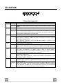
INDEX
EN
INDICE
IT
RECOMMENDATIONS AND SUGGESTIONS ..................................................................................................................... 3
CHARACTERISTICS ............................................................................................................................................................. 4
CHARACTERISTICS ............................................................................................................................................................. 5
INSTALLATION...................................................................................................................................................................... 6
USE ........................................................................................................................................................................................ 9
MAINTENANCE ................................................................................................................................................................... 11
CONSIGLI E SUGGERIMENTI............................................................................................................................................ 13
CARATTERISTICHE............................................................................................................................................................ 14
CARATTERISTICHE............................................................................................................................................................ 15
INSTALLAZIONE ................................................................................................................................................................. 16
USO...................................................................................................................................................................................... 19
MANUTENZIONE ................................................................................................................................................................ 21
SOMMAIRE
FR
INHALTSVERZEICHNIS
DE
IÇERIKLER
TR
CONSEILS ET SUGGESTIONS.......................................................................................................................................... 23
CARACTERISTIQUES......................................................................................................................................................... 24
CARACTERISTIQUES......................................................................................................................................................... 25
INSTALLATION.................................................................................................................................................................... 26
UTILISATION ....................................................................................................................................................................... 29
ENTRETIEN......................................................................................................................................................................... 31
EMPFEHLUNGEN UND HINWEISE ................................................................................................................................... 33
CHARAKTERISTIKEN ......................................................................................................................................................... 34
CHARAKTERISTIKEN ......................................................................................................................................................... 35
MONTAGE ........................................................................................................................................................................... 36
BEDIENUNG........................................................................................................................................................................ 39
WARTUNG........................................................................................................................................................................... 41
TAVSIYELER VE ÖNERILER.............................................................................................................................................. 43
ÖZELLIKLER........................................................................................................................................................................ 44
ÖZELLIKLER........................................................................................................................................................................ 45
MONTAJ............................................................................................................................................................................... 46
KULLANIM ........................................................................................................................................................................... 49
BAKIM .................................................................................................................................................................................. 51
2
2
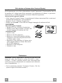
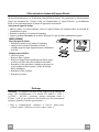
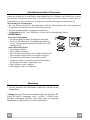
RECOMMENDATIONS AND SUGGESTIONS
The Instructions for Use apply to several versions of this appliance. Accordingly, you may find
descriptions of individual features that do not apply to your specific appliance.
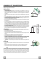
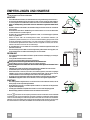
INSTALLATION
• The manufacturer will not be held liable for any damages resulting from incorrect or improper
installation.
• The minimum safety distance between the cooker top and the extractor hood is 650 mm (some
models can be installed at a lower height, please refer to the paragraphs on working dimensions
and installation).
• Check that the mains voltage corresponds to that indicated on the rating plate fixed to the inside of
the hood.
• For Class I appliances, check that the domestic power supply guarantees adequate earthing.
Connect the extractor to the exhaust flue through a pipe of minimum diameter 120 mm. The route
of the flue must be as short as possible.
• Do not connect the extractor hood to exhaust ducts carrying combustion fumes (boilers, fireplaces,
etc.).
• If the extractor is used in conjunction with non-electrical appliances (e.g. gas burning appliances), a
sufficient degree of aeration must be guaranteed in the room in order to prevent the backflow of
exhaust gas. The kitchen must have an opening communicating directly with the open air in order
to guarantee the entry of clean air. When the cooker hood is used in conjunction with appliances
supplied with energy other than electric, the negative pressure in the room must not exceed 0,04
mbar to prevent fumes being drawn back into the room by the cooker hood.
• In the event of damage to the power cable, it must be replaced by the manufacturer or by the
technical service department, in order to prevent any risks.
• If the instructions for installation for the gas hob specify a greater distance specified above, this has
to be taken into account. Regulations concerning the discharge of air have to be fulfilled.
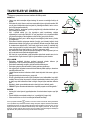
650 mm min.
2°
USE
•
•
•
•
•
•
•
•
•
The extractor hood has been designed exclusively for domestic use to eliminate kitchen smells.
Never use the hood for purposes other than for which it has been designed.
Never leave high naked flames under the hood when it is in operation.
Adjust the flame intensity to direct it onto the bottom of the pan only, making sure that it does not
engulf the sides.
Deep fat fryers must be continuously monitored during use: overheated oil can burst into flames.
Do not flambè under the range hood; risk of fire
This appliance is not intended for use by persons (including children) with reduced physical, sensory or mental capabilities, or lack of experience and knowledge, unless they have been given supervision or instruction concerning use of the appliance by a person responsible for their safety.
Children should be supervised to ensure that they do not play with the appliance.
“ CAUTION: Accessible parts may become hot when used with cooking appliances.”.
MAINTENANCE
• Switch off or unplug the appliance from the mains supply before carrying out any maintenance
work.
• Clean and/or replace the Filters after the specified time period (Fire hazard).
• Clean the hood using a damp cloth and a neutral liquid detergent.
The symbol
on the product or on its packaging indicates that this product may not be treated as household waste. Instead it shall be handed over to the
applicable collection point for the recycling of electrical and electronic equipment. By ensuring this product is disposed of correctly, you will help prevent potential negative
consequences for the environment and human health, which could otherwise be caused by inappropriate waste handling of this product. For more detailed information
about recycling of this product, please contact your local city office, your household waste disposal service or the shop where you purchased the product.
EN
3
3
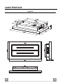
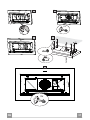
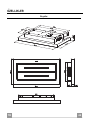
CHARACTERISTICS
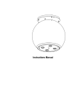
Dimensions
EN
4
4
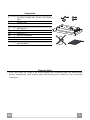
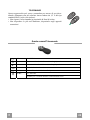
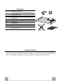
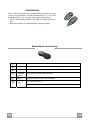
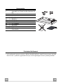
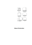
Components
Ref.
1
2
Q.ty Product Components
1 Hood Body, complete with: Controls, Light, Blower,
Filters.
Charcoal Filters.
Ref.
11
12g
12h
22
23
Q.ty
4
4
4
4
4
Installation Components
Wall Plugs ø 10
Screws M6 x 80
Screws 5,2 x 70
6.4 mm int. dia washers
M6 nuts
2
Q.ty Documentation
1 Instruction Manual
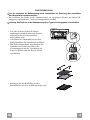
Fixing the Hood
• In all cases where the ceiling is not strong enough at the suspension point, the installer must
provide strengthening using suitable plates and backing pieces anchored to the structurally
sound parts.
EN
5
5
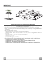
INSTALLATION
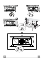
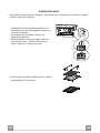
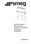
Drilling the Ceiling/shelf and fixing the frame
DRILLING THE CEILING/SHELF
• Use a plumb line to mark the centre of the hob on the ceiling/support shelf.
• Using the measurements of the Dimensional Drawing, mark the holes for the installation.
• Drill the holes at the points marked:
• For concrete ceilings, drill for plugs appropriate to the screw size.
• For hollow brick ceilings with wall thickness of 20 mm: drill ø 10 mm(immediately insert
the Dowels 11 supplied).
• For wooden beam ceilings, drill according to the wood screws used.
• For wooden shelf, drill ø 7 mm.
• For the power supply cable feed, drill ø 10 mm.
• For the air outlet (Ducted Version), drill according to the diameter of the external air exhaust duct connection.
• Insert two screws of the following type, crossing them and leaving 4-5 mm from the ceiling:
• For concrete ceilings, use the appropriate plugs for the screw size (not provided).
• for Cavity ceiling with inner space, with wall thickness of approx. 20 mm, Screws 12h,
supplied.
• For wooden beam ceilings, use 4 wood screws (not provided).
• For wooden shelf, use 4 screws 12g with washers 22 and nuts 23, provided.
EN
6
6
a
b
6x
c
d
e
4x
EN
7
7
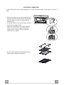
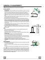
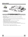
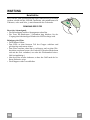
ELECTRICAL CONNECTION
• Connect the hood to the mains through a two-pole switch having a contact gap of at least 3
mm..
• Before carrying out any operation the Hood
must be disconnected by removing the plug
from the power socket or turning off the
main switch.
• From the inside of the hood canopy connect
up the power supply cable.
• Open the terminal box by unfastening the
screws on cover (A), connect the power
supply to the wiring in the box and then
close the cover again.
• Fix the Charcoal Filter on the Metal grease
filters like as indicated in picture.
EN
8
8
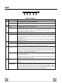
USE
S1
L
T1
T2
T3
T4
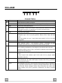
Control panel
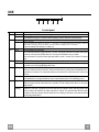
Button Led
L
T1
Fixed
Function
Turns the lights ON/OFF at maximum strength.
Press and hold for approx. 2 seconds to turn the lighting system on and off at reduced intensity.
Turns the motor on/off at speed one.
Delay function:
Press and hold the button for approx. 3 seconds to Activate/Deactivate the Delay function
(automatic switching off of the Motor, the Fans and the Lighting with a 30' delay).
T2
Fixed
T3
Fixed
T4
Fixed
S1
Fixed
Flashing
EN
Cannot be enabled when Intensive or 24h are on.
Turns the Motor on at speed two.
Press and hold the button for approximately 5 seconds, with all the loads turned off (Motor and Lights),
to turn the Activated Charcoal Filter alarm on. The relevant LED flashes twice to confirm.
To turn the alarm off, press the button again and hold for at least 5 seconds. The relevant LED flashes
once.
Turns the Motor on at speed three.
Press and hold the button for approximately 3 seconds, with all the loads turned off (Motor and Lights),
to perform a reset. The LED S1 flashes three times.
Turns the Motor on at INTENSIVE Speed.
This speed is timed to run for 6 minutes. At the end of this time, the system returns automatically to the
speed that was set before. If it is activated with the motor turned off, it will switch to OFF at the end of
the time.
Press and hold for 5 seconds to enable the remote control, indicated by the LED flashing twice.
Press and hold for 5 seconds to disable the remote control, indicated by the LED flashing just once.
Signals the Metal Grease Filter saturation alarm, indicating that it is necessary to wash the filters. The
alarm is triggered after the Hood has been in operation for 100 working hours. (Reset see the parag.
Maintenance)
When this is activated, it signals the Activated Charcoal Filter saturation alarm, indicating that the filter
must be changed; the Metal Grease Filters must also be washed. The Activated Charcoal Filter saturation alarm comes into operation after the Hood has been working for 200 hours. (Activation and Reset
see the parag. Maintenance)
9
9
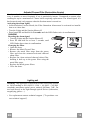
REMOTE CONTROL
The appliance can be controlled using a remote control powered
by a 1.5 V carbon-zinc alkaline batteries of the standard LR03AAA type (not included).
• Do not place the remote control near to heat sources.
• Used batteries must be disposed of in the proper manner.
Remote control panel
Motor
Motor On / Off.
Decreases the working speed each time it is pressed.
Increases the working speed each time it is pressed.
Intensive
Activates the Intensive function
Delay
Activates / Deactivates the Delay function
Light
Lights On / Off
Press for 2 seconds to modify the intensity of the Light.
EN
1
10
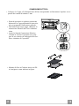
MAINTENANCE
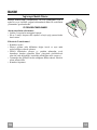
Metal grease filters
These can be washed in the dishwasher, and need to be cleaned
whenever the S1 Led comes on or at least once every 2 months
use, or more frequently if use is particularly intensive.
CLEANING THE FILTERS
Resetting the alarm signal
• Turn the Lights and the Suction Motor off.
• Press T3 and hold for at least 3 seconds, until LED flashes
three times in confirmation.
Cleaning the Filters
• Open the doors.
• Remove the Filter, pushing it towards the back of the unit and
at the same time pulling downward.
• Wash the filter without bending it, and leave it to dry thoroughly before replacing (if the surface of the filter changes
colour over time, this will have absolutely no effect on its efficiency).
• Replace, taking care to ensure that the handle faces forwards.
• Close the doors again.
EN
1
11
Activated Charcoal Filter (Recirculation Version)
Can be washed in the dishwasher. It must be washed when Led S1 flashes or at least once
every 4 months, or more frequently if use is particularly intense. Guaranteed to operate after
washing for up to a maximum of 5 times before requiring replacement. The Alarm signal, if it
has been activated, only appears when the Suction motor is turned on.
Activating the alarm signal
• In Recirculation Version Hoods, the Filter Saturation Alarm must be activated on installation or at a later date.
• Turn the Lights and the Suction Motor off.
• Press button T2 and hold it for 5 seconds until the LED flashes twice in confirmation:
CHANGING
Resetting the alarm signal
• Turn the Lights and the Suction Motor off.
• Press T3 and hold for at least 3 seconds, until
LED flashes three times in confirmation.
Changing the Filter
• Open the doors.
• Remove the Metal Grease Filter.
• Remove the metal filter stops from the grease
filter and clean the saturated activated charcoal
odour filter.
• Replace the clean activated charcoal odour filter,
hooking it back up to the grease filter using the
metal filter stops.
• Replace the Metal grease filters.
• Close the doors.
Lighting unit
Warning: This appliance is fitted with a white LED lamp classed
as 1M according to EN 60825-1: 1994 + A1:2002 + A2:2001
standards; maximum optical power emitted @439nm: 7µW. Do
not look directly at the light through optical devices (binoculars,
magnifying glasses…).
• For replacement contact technical support. ("To purchase contact technical support")
EN
1
12
CONSIGLI E SUGGERIMENTI
Questo libretto di istruzioni per l'uso è previsto per più versioni dell' apparecchio. É possibile che siano
descritti singoli particolari della dotazione, che non riguardano il Vostro apparecchio.
INSTALLAZIONE
• Il produttore declina qualsiasi responsabilità per danni dovuti ad installazione non corretta o non conforme
alle regole dell’arte.
• La distanza minima di sicurezza tra il Piano di cottura e la Cappa deve essere di 650 mm, (alcuni modelli
possono essere installati ad un’altezza inferiore, fare riferimento ai paragrafi ingombro e installazione).
• Verificare che la tensione di rete corrisponda a quella riportata nella targhetta posta all’interno della Cappa.
• Per Apparecchi in Classe Ia accertarsi che l’impianto elettrico domestico garantisca un corretto scarico a
terra.
• Collegare la Cappa all’uscita dell’aria aspirata con tubazione di diametro pari o superiore a 120 mm. Il
percorso della tubazione deve essere il più breve possibile.
• Non collegare la Cappa a condotti di scarico dei fumi prodotti da combustione (caldaie, caminetti, ecc.).
• Nel caso in cui nella stanza vengano utilizzati sia la Cappa che apparecchi non azionati da energia elettrica
(ad esempio apparecchi utilizzatori di gas), si deve provvedere ad una aerazione sufficiente dell’ambiente.
Se la cucina ne fosse sprovvista, praticare un’apertura che comunichi con l’esterno, per garantire il richiamo d’aria pulita. Un uso proprio e senza rischi si ottiene quando la depressione massima del locale non
supera i 0,04 mBar.
• In caso di danneggiamento del cavo alimentazione, esso deve essere sostituito dal costruttore o dal servizio di assistenza tecnica, in modo da prevenire ogni rischio.
• Se le istruzioni di installazione del dispositivo di cottura a gas indicano che è necessaria una distanza
maggiore di quella indicato sopra, è necessario tenerne conto. Bisogna rispettare tutte le normative relative
allo scarico dell’aria.
650 mm min.
2°
USO
•
•
•
•
•
•
•
•
•
La Cappa è stata progettata esclusivamente per uso domestico, per abbattere gli odori della cucina.
Non fare mai uso improprio della Cappa.
Non lasciare fiamme libere a forte intensità sotto la Cappa in funzione.
Regolare sempre le fiamme in modo da evitare una evidente fuoriuscita laterale delle stesse rispetto al
fondo delle pentole.
Controllare le friggitrici durante l’uso: l’olio surriscaldato potrebbe infiammarsi.
Non preparare alimenti flambè sotto la cappa da cucina; pericolo d'incendio.
Questo apparecchio non deve essere utilizzato da persone (bambini inclusi) con ridotte capacità psichiche,
sensoriali o mentali, oppure da persone senza esperienza e conoscenza, a meno che non siano controllati
o istruiti all’uso dell’apparecchio da persone responsabili della loro sicurezza.
I bambini devono essere supervisionati per assicurarsi che non giochino con l’apparecchio.
“ATTENZIONE: Le parti accessibili possono diventare molto calde se utilizzate con degli apparecchi di
cottura”.
MANUTENZIONE
• Prima di procedere a qualsiasi operazione di manutenzione, disinserire la Cappa togliendo la spina elettrica o spegnendo l’interruttore generale.
• Effettuare una scrupolosa e tempestiva manutenzione dei Filtri secondo gli intervalli consigliati (Rischio di
incendio).
• Per la pulizia delle superfici della Cappa è sufficiente utilizzare un panno umido e detersivo liquido neutro.
Il simbolo
sul prodotto o sulla confezione indica che il prodotto non deve essere considerato come un normale
rifiuto domestico, ma deve essere portato nel punto di raccolta appropriato per il riciclaggio di apparecchiature elettriche
ed elettroniche. Provvedendo a smaltire questo prodotto in modo appropriato, si contribuisce a evitare potenziali conseguenze negative per l’ambiente e per la salute, che potrebbero derivare da uno smaltimento inadeguato del prodotto.
Per informazioni più dettagliate sul riciclaggio di questo prodotto, contattare l’ufficio comunale, il servizio locale di smaltimento rifiuti o il negozio in cui è stato acquistato il prodotto.
IT
1
13
CARATTERISTICHE
Ingombro
IT
1
14
Componenti
Rif.
1
Q.tà Componenti di Prodotto
1 Corpo Cappa completo di: Comandi, Luce, Filtri, Motore.
Filtro al Carbone attivo.
2
Rif.
11
12g
12h
22
23
Q.tà
4
4
4
4
4
Componenti di Installazione
Tasselli ø 10
Viti M6 x 80
Viti 5,2 x 70
Rondelle ø 6,4
Dadi M6
Q.tà Documentazione
1 Libretto Istruzioni
2
Fissaggio Cappa
In tutti i casi in cui il Soffitto non fosse sufficientemente robusto sul punto di sospensione,
l’Installatore dovrà provvedere a irrobustirlo con opportune piastre e contropiastre ancorate a
parti strutturalmente resistenti.
IT
1
15
INSTALLAZIONE
Foratura Soffitto/Mensola e Fissaggio Traliccio
FORATURA SOFFITTO/MENSOLA
• Con l’ausilio di un Filo a piombo riportare sul Soffitto/Mensola di supporto il centro del
Piano di Cottura.
• Usando le misure del Disegno Dimensionale, segnare i fori per l’installazione.
• Forare i punti seguenti:
• Soffitto in Calcestruzzo massiccio: secondo Tasselli per Calcestruzzo impiegati.
• Soffitto in Laterizio a camera d’aria, con spessore resistente di 20 mm: ø 10 mm (inserire
subito i Tasselli 11 in dotazione).
• Soffitto in Travatura di Legno: secondo Viti per Legno impiegate.
• Mensola in Legno: ø 7 mm.
• Passaggio del Cavo elettrico di Alimentazione: ø 10 mm.
• Avvitare, incrociandole e lasciando 4-5 mm dal soffitto le viti:
• per Calcestruzzo massiccio, Tasselli per Calcestruzzo, non in dotazione.
• per Laterizio a camera d’aria, con spessore resistente di 20 mm circa, Viti 12h, in dotazione.
• per Travatura di legno, Viti per legno, non in dotazione.
• per Mensola in Legno, viti 12g con Rondelle 22 e Dadi 23, in dotazione.
IT
1
16
a
b
6x
c
d
e
4x
IT
1
17
CONNESSIONE ELETTRICA
• Collegare la Cappa all’Alimentazione di Rete interponendo un Interruttore bipolare con apertura dei contatti di almeno 3 mm.
• Prima di procedere a qualsiasi operazione
disinserire la Cappa togliendo la spina elettrica o spegnendo l’interruttore generale.
• Dall’interno del corpo cappa, effettuare la
connessione Elettrica del Cavo Alimentazione.
• Aprire la Scatola Connessione Elettrica
svitando le Viti del Coperchio (A), collegare la rete elettrica al cablaggio nella Scatola e richiudere il Coperchio.
• Montare il filtro al Carbone Attivo sui Filtri Antigrasso come indicato in figura.
IT
1
18
USO
S1
L
T1
T2
T3
T4
Quadro comandi
Tasto Led
L -
Funzione
Accende/Spegne le luci alla massima luminosità.
Premuto per 2 secondi circa accende/spegne l’impianto d’illuminazione ad intensità ridotta.
T1
T2
Fisso
Accende/Spegne il motore alla prima velocità.
Lampeggiante
Funzione Delay:
Tenendo premuto il tasto per circa 3 sec., Attiva/Disattiva la funzione Delay (lo spegnimento automatico del Motore, delle Ventole e dell’Illuminazione ritardato di 30’).
Fisso
Non attivabile con Intensiva o 24h accesi.
Accende il motore alla seconda velocità.
Tenendo il tasto premuto per circa 5 secondi, quando tutti i carichi sono spenti (Motore+Luce), si attiva l’allarme dei Filtri al Carbone attivo visualizzando un doppio lampeggio del relativo Led.
Per disattivarlo, si preme di nuovo il tasto per altri 5 secondi visualizzando un lampeggio
singolo del relativo Led.
T3
Fisso
Accende il motore alla terza velocità.
Tenendo premuto il tasto per circa 3 secondi, quando tutti i carichi sono spenti (Motore+Luce), si effettua il reset visualizzando il triplo lampeggio del Led S1.
T4
S1
Fisso
Fisso
Lampeggiante
IT
Accende il motore alla velocità INTENSIVA.
Questa velocità è temporizzata a 6 minuti. Terminato il tempo, il sistema ritorna automaticamente alla velocità precedentemente selezionata. Se attivata da motore spento una
volta finito il tempo passa alla modalità OFF.
Tenendo premuto per 5 secondi si abilità il telecomando visualizzando un doppio lampeggio del medesimo led.
Tenendo il tasto premuto per 5 secondi si disabilita il telecomando visualizzando il lampeggio del rispettivo led una sola volta.
Segnala l’allarme saturazione Filtri Antigrasso Metallici e la necessità di lavarli. L’allarme
entra in funzione dopo 100 ore di lavoro effettivo della Cappa. (Reset vedi parag. Manutenzione)
Segnala, quando è attivato, l’allarme saturazione Filtro Antiodore al Carbone Attivo, che
deve essere sostituito; devono anche essere lavati i Filtri Antigrasso Metallici. L’allarme
saturazione Filtro Antiodore al Carbone Attivo entra in funzione dopo 200 ore di lavoro
effettivo della Cappa. (Attivazione e Reset vedi parag. Manutenzione)
1
19
TELECOMANDO
Questo apparecchio può essere comandato per mezzo di un telecomando, alimentato con pile alcaline zinco-carbone da 1,5 V del tipo
standard LR03-AAA (non incluse).
• Non riporre il telecomando in prossimità di fonti di calore.
• Non disperdere le pile nell’ambiente, depositarle negli appositi
contenitori.
Quadro comandi Telecomando
Motore
On / Off Motore
Decrementa la velocità di esercizio ad ogni pressione.
Incrementa la velocità di esercizio ad ogni pressione.
Intensiva
Attiva la funzione Intensiva
Delay
Attiva / Disattiva la funzione Delay
Luce
On / Off Luci
Premuto per 2 secondi modifica l’intensità della Luce.
IT
2
20
MANUTENZIONE
Filtri antigrasso metallici
Sono lavabili in lavastoviglie, e necessitano di essere lavati quando il Led S1 si accende o almeno ogni 2 mesi circa di utilizzo o
più frequentemente, per un uso particolarmente intenso.
PULIZIA FILTRI
Reset del segnale di allarme
• Spegnere le Luci e il Motore di aspirazione.
• Premere il tasto T3 per almeno 3 secondi, sino al triplo lampeggio di conferma del Led.
Pulizia Filtri
• Aprire le Ante.
• Togliere il Filtro spingendolo verso la parte posteriore del
gruppo e tirando contemporaneamente verso il basso.
• Lavare il filtro evitando di piegarlo, e lasciarlo asciugare prima
di rimontarlo (un’eventuale cambiamento del colore della superficie del filtro, che potrebbe verificarsi nel tempo, non pregiudica assolutamente l’efficienza dello stesso).
• Rimontarlo facendo attenzione a mantenere la maniglia verso
la parte visibile esterna.
• Richiudere le Ante.
IT
2
21
Filtri antiodore al Carbone attivo (Versione Filtrante)
Lavabile anche in lavastoviglie va pulito quando lampeggia il Led S1 o almeno ogni 4 mesi o
più frequentemente, per un uso particolarmente intenso, garantendo il funzionamento fino ad
un massimo di 5 lavaggi prima della sostituzione. La segnalazione di Allarme, se preventivamente attivata, si verifica solo quando è azionato il Motore di aspirazione.
Attivazione del segnale di allarme
• Nelle Cappe in Versione Filtrante, la segnalazione di Allarme saturazione Filtri va attivata al
momento dell’installazione o successivamente.
• Spegnere le Luci e il Motore di aspirazione.
• Premere per 5 secondi il Tasto T2 sino al doppio lampeggio di conferma del Led.
SOSTITUZIONE
Reset del segnale di allarme
• Spegnere le Luci e il Motore di aspirazione.
• Premere il tasto T3 per almeno 3 secondi, sino
al triplo lampeggio di conferma del Led.
Sostituzione Filtro
• Aprire le Ante.
• Rimuovere il Filtro antigrasso.
• Rimuovere i ferma filtro metallici dal Filtro
Antigrasso e procedere alla pulizia del Filtro
al Carbone attivo saturo.
• Rimontare il Filtro antiodore al Carbone attivo
pulito riagganciandolo coi ferma filtro metallici al Filtro Antigrasso.
• Rimontare il Filtro antigrasso.
• Chiudere le Ante.
Illuminazione
Attenzione: Questo apparecchio è provvisto di una luce LED
bianca di classe 1M secondo la norma EN 60825-1: 1994 +
A1:2002 + A2:2001; massima potenza ottica emessa@439nm:
7µW. Non osservare direttamente con strumenti ottici (binocolo,
lente d’ingrandimento….).
• Per la sostituzione contattare l’Assistenza Tecnica. ("Per l'acquisto rivolgersi all'assistenza tecnica").
IT
2
22
CONSEILS ET SUGGESTIONS
La présente notice d'emploi vaut pour plusieurs versions de l'appareil. Elle peut contenir des descriptions d'accessoires ne figurant pas dans votre appareil.
INSTALLATION
• Le fabricant décline toute responsabilité en cas de dommage dû à une installation non correcte ou non
conforme aux règles de l’art.
• La distance minimale de sécurité entre le plan de cuisson et la hotte doit être de 650 mm au moins (certains
modèles peuvent être installés à une hauteur inférieure : se reporter aux paragraphes « Encombrement » et
« Installation »).
• Vérifier que la tension du secteur correspond à la valeur qui figure sur la plaquette apposée à l’intérieur de la
hotte.
• Pour les Appareils appartenant à la Ière Classe, veiller à ce que la mise à la terre de l’installation électrique
domestique ait été effectuée conformément aux normes en vigueur.
• Connecter la hotte à la sortie d’air aspiré à l’aide d’une tuyauterie d’un diamètre égal ou supérieur à 120 mm. Le
parcours de la tuyauterie doit être le plus court possible.
• Ne pas connecter la hotte à des conduites d’évacuation de fumées issues d’une combustion tel que (Chaudière, cheminée, etc…).
• Si vous utilisez des appareils qui ne fonctionnent pas à l’électricité dans la pièce ou est installée la hotte (par
exemple: des appareils fonctionnant au gaz), vous devez prévoir une aération suffisante du milieu. Si la cuisine
en est dépourvue, pratiquez une ouverture qui communique avec l’extérieur pour garantir l’infiltration de l’air pur.
Pour un emploi correct et sans risque, la dépression maximum dans la pièce ne doit pas dépasser 0,04 mbar.
• En cas d’endommagement du cordon d’alimentation, faites-le remplacer par le constructeur ou par le service
après-vente, afin de prévenir tout risque.
• Si les instructions de montage pour la plaque de cuisson au gaz spécifient une plus grande distance indiquée cidessus, cela doit être pris en compte. Règlement concernant l'évacuation d'air doivent être remplies..
650 mm min.
2°
UTILISATION
•
•
•
•
•
•
•
•
•
La hotte a été conçue exclusivement pour l’usage domestique, dans le but d’éliminer les odeurs de la cuisine.
Ne jamais utiliser abusivement la hotte.
Ne pas laisser les flammes libres à forte intensité quand la hotte est en service.
Toujours régler les flammes de manière à éviter toute sortie latérale de ces dernières par rapport au fond des
marmites.
Contrôler les friteuses lors de l’utilisation car l’huile surchauffée pourrait s’enflammer.
Ne pas préparer d’aliments flambés sous la hotte de cuisine : risque d’incendie
Cet appareil ne doit pas être utilisé par des personnes (y compris les enfants) ayant des capacités psychiques,
sensorielles ou mentales réduites, ni par des personnes n’ayant pas l’expérience et la connaissance de ce type
d’appareils, à moins d'être sous le contrôle et la formation de personnes responsables de leur sécurité.
Les enfants doivent être surveillés pour s'assurer qu'ils ne jouent pas avec l'appareil.
« ATTENTION : Les parties accessibles peuvent devenir très chaudes si utilisées avec des appareils de cuisson. »
ENTRETIEN
• Avant de procéder à toute opération d’entretien, retirer la hotte en retirant la fiche ou en actionnant l’interrupteur
général.
• Effectuer un entretien scrupuleux et en temps dû des Filtres, à la cadence conseillée (Risque d’incendie).
• Pour le nettoyage des surfaces de la hotte, il suffit d’utiliser un chiffon humide et détersif liquide neutre.
Le symbole
sur le produit ou son emballage indique que ce produit ne peut être traité comme déchet ménager. Il
doit plutôt être remis au point de ramassage concerné, se chargeant du recyclage du matériel électrique et électronique.
En vous assurant que ce produit est éliminé correctement, vous favorisez la prévention des conséquences négatives
pour l’environnement et la santé humaine qui, sinon, seraient le résultat d’un traitement inapproprié des déchets de ce
produit. Pour obtenir plus de détails sur le recyclage de ce produit, veuillez prendre contact avec le bureau municipal de
votre région, votre service d’élimination des déchets ménagers ou le magasin où vous avez acheté le produit.
FR
2
23
CARACTERISTIQUES
Encombrement
FR
2
24
Composants
Réf.
1
Q.té Composants de Produit
1 Corps Hotte équipé de: Comandes, Lumière, Filtres
Filtre à charbon actif.
2
Réf.
11
12g
12h
22
23
Q.té
4
4
4
4
4
Composants pour l’installation
Chevilles ø 10
Vis M6 x 80
Vis 5,2 x 70
Rondelles øi 6,4
Écrous M6
2
Q.té Documentation
1 Manuel d’instructions
Fixation de la Hotte
• Dans tous les cas où le Plafond ne devait pas être suffisamment robuste en correspondance du
point d’accrochage, l’Installateur devra se charger de le rendre plus solide au moyen de plaques et contre-plaques spéciales, ancrées sur les parties structuralement résistantes.
FR
2
25
INSTALLATION
Perçage plafond/étagère et fixation treillis
PERÇAGE PLAFOND/ÉTAGÈRE
• À l’aide d’un fil à plomb, reporter sur le plafond/étagère de support le centre du plan de
cuisson.
• En utilisant les dimensions indiquées dans le croquis, marquer les trous pour l’installation.
• Percer les points suivants :
• Plafond en béton massif : en fonction des chevilles pour béton utilisées.
• Plafond en briques et chambre à air, avec une épaisseur résistante de 20 mm : ø 10 mm
(insérer immédiatement les chevilles 11 fournies).
• Plafond en poutres de bois : en fonction des vis à bois utilisées.
• Étagère en bois : ø 7 mm.
• Passage du câble électrique d’alimentation : ø 10 mm.
• Serrer en diagonale, en laissant les vis à 4-5 mm du plafond :
• pour le béton massif, les chevilles pour béton ne sont pas fournies.
• pour briques avec chambre à air, avec une épaisseur résistante d’environ 20 mm, les vis
12h sont fournies.
• pour les poutres en bois, les vis à bois ne sont pas fournies.
• pour étagère en bois, les vis 12g avec les rondelles 22 et les écrous 23 sont fournies.
FR
2
26
a
b
6x
c
d
e
4x
FR
2
27
BRANCHEMENT ELECTRIQUE
• Brancher la hotte sur le secteur en interposant un interrupteur bipolaire avec ouverture des
contacts d’au moins 3 mm.
• Avant d’effectuer toute opération,
débrancher la hotte en retirant la fiche de la
prise ou en débranchant l’interrupteur
général.
• En passant par l’intérieur du corps de hotte,
effectuer la connexion électrique du câble
d’alimentation.
• Ouvrir la boîte de connexion électrique en
desserrant les vis du couvercle (A), brancher
le secteur au câblage dans la boîte et
refermer le couvercle.
• Fixer le Filtres anti-odeur à charbon actif sur
le Filtres à graisse métalliques comme
indiqué dans l'image.
FR
2
28
UTILISATION
S1
L
T1
T2
T3
T4
Tableau des commandes
Touche
L
T1
Led
-
Fonction
Allume/Éteint les lumières à la luminosité maximum.
L’appui sur la touche pendant environ 2 secondes, branche/débranche l’éclairage à faible
intensité.
Démarre/Coupe le moteur en première vitesse.
Fixe
Clignotan Fonction Delay :
Garder la touche appuyée pendant environ 3 secondes pour activer/désactiver la fonction
te
Delay (l’extinction automatique du moteur, des ventilateurs et de l’éclairage différé de 30’).
T2
T3
T4
S1
FR
Non activable si le mode Intensive ou 24h sont actifs.
Démarre le moteur en deuxième vitesse.
Garder la touche appuyée pendant environ 5 secondes, lorsque toutes les charges sont
éteintes (Moteur+ Éclairage), l’alarme des filtres au charbon actif s’active et la led
correspondante clignotera 2 fois.
Pour la désactiver, appuyer de nouveau sur la touche pendant 5 secondes. La led
correspondante clignotera 1 fois.
Fixe
Démarre le moteur en troisième vitesse.
Garder la touche appuyée pendant environ 3 secondes, lorsque toutes les charges sont
éteintes (Moteur+ Éclairage), le reset est effectué et la led S1 correspondante clignotera 3
fois.
Démarre le moteur à la vitesse INTENSIVE.
Fixe
Cette vitesse est temporisée à 6 minutes. Après ce délai, le système retourne
automatiquement à la vitesse précédemment sélectionnée. Si activée à partir du moteur à
l’arrêt, à la fin du délai préfixé le système passe en mode OFF.
Garder la touche appuyée pendant environ 5 secondes pour valider la télécommande. La led
correspondante clignote 2 fois.
Garder la touche appuyée pendant 5 secondes pour invalider la télécommande. La led
correspondante clignote 1 seule fois
Fixe
Signale l’alarme saturation filtres à graisse métalliques et la nécessité de les laver. L’alarme
se déclenche après 100 heures de fonctionnement effectif de la hotte. (Pour le reset, voir le
paragraphe Entretien)
Clignotan Signale, lorsque l’alarme de saturation du filtre anti-odeur à charbon actif est activée, que le
te
filtre doit être remplacé. Laver aussi les filtres à graisse métalliques. L’alarme de saturation
du filtre anti-odeur à charbon actif entre en fonction après 200 heures de fonctionnement
effectif de la hotte. (Activation et Restauration voir parag. Entretien)
Fixe
2
29
TELECOMMANDE
Il est possible de commander cet appareil au moyen d’une télécommande, alimentée avec des piles alcalines zinc-charbon 1,5 V
du type standard LR03-AAA25 (ne fournis pas).
• Ne pas ranger la télécommande à proximité de sources de chaleur.
• Ne pas jeter les piles; il faut les déposer dans les récipients de
récolte spécialement prévus à cet effet.
Tableau des commandes – Télécommande
Moteur
Moteur On / Off .
Diminue la vitesse de fonctionnement à chaque appui.
Augmente la vitesse de fonctionnement à chaque appui.
Intensive
Active la fonction Intensive
Delay
Active / Débranche la fonction Delay
Éclairage
Éclairage On / Off
Appuyée pendant 2 secondes elle modifie l’intensité de la lumière.
FR
3
30
ENTRETIEN
Filtres à graisse métalliques
Ils peuvent être lavés au lave-vaisselle et doivent être lavés quand
la led S1 s’allume ou au moins tous les 2 mois d’utilisation ou
plus fréquemment en cas d’utilisation particulièrement intensive.
NETTOYAGE FILTRES
Reset du signal d'alarme
• Éteindre les lumières et le moteur d’aspiration.
• Appuyer sur la touche T3 pendant au moins 3 secondes
jusqu’au triple clignotement de confirmation de la led.
Nettoyage filtres
• Ouvrir les portes
• Retirer le filtre en le poussant vers l’arrière du groupe et en
tirant en même temps vers le bas.
• Laver le filtre en évitant de le plier, et le laisser sécher avant de
le remonter (tout changement de couleur de la surface du filtre,
susceptible de se produire avec le temps, ne nuit en rien à
l’efficacité de ce dernier).
• Le remonter en faisant attention de garder la poignée vers la
partie visible externe.
• Refermer les portes.
FR
3
31
Filtres anti-odeur à charbon actif (version filtrante)
Également lavable au lave-vaisselle, le nettoyer lorsque la Led S1 clignote ou au moins tous les 4 mois
ou plus fréquemment en cas d’utilisation particulièrement intense, en garantissant le fonctionnement
jusqu’à un maximum de 5 lavages avant son remplacement. Le signal d’alarme, si préalablement
activé, a lieu seulement lorsque le moteur d’aspiration est en marche.
Activation du signal d’alarme
• Dans les hottes en version filtrante, activer le signal d’alarme de saturation filtres au moment de
l’installation ou après.
• Éteindre les lumières et le moteur d’aspiration.
• Appuyer pendant 5 secondes sur la touche T2 jusqu’à ce que la led de confirmation clignote :
REMPLACEMENT
Reset du signal d'alarme
• Éteindre les lumières et le moteur d’aspiration.
• Appuyer sur la touche T3 pendant au moins 3
secondes jusqu’au triple clignotement de confirmation
de la led.
Remplacement du filtre
• Ouvrir les portes
• Retirer le filtre à graisse
• Retirer les bloque-filtres métalliques du filtre à graisse
et nettoyer le filtre anti-odeur à charbon actif saturé.
• Remonter le filtre anti-odeur à charbon actif propre en
le raccrochant au filtre à graisse à l’aide des bloquefiltres métalliques.
• Remonter le filtre à graisse
• Refermer les portes.
Éclairage
Attention : Cet appareil est doté d’une lumière LED blanche de
classe 1M conformément à la norme EN 60825-1: 1994 +
A1:2002 + A2:2001 : puissance optique maximum émise à
439nm : 7µW. Ne pas observer directement avec des instruments
optiques (jumelles, lentilles grossissantes…)
• Pour le remplacement, contacter le Service après-vente.
(« Pour l’achat, s’adresser au service après-vente »).
FR
3
32
EMPFEHLUNGEN UND HINWEISE
Diese Gebrauchsanleitung gilt für mehrere Geräte-Ausführungen. Es ist möglich, dass einzelne Ausstattungsmerkmale beschrieben sind, die nicht auf Ihr Gerät zutreffen.
MONTAGE
• Der Hersteller haftet nicht für Schäden, die auf eine fehlerhafte oder unsachgemäße Montage zurückzuführen sind.
• Der minimale Sicherheitsabstand zwischen Kochmulde und Haube muss 650 mm betragen (einige Modelle können an einer geringeren Höhe installiert werden, beziehen Sie sich dazu auf den Absatz Platzbedarf und Installation).
• Prüfen, ob die Netzspannung mit dem Wert auf dem im Haubeninneren angebrachten Schild übereinstimmt.
• Bei Geräten der Klasse I ist sicherzustellen, dass die elektrische Anlage des Wohnhauses über eine vorschriftsmäßige Erdung verfügt.
• Das Anschlussrohr der Haube zur Luftaustrittsöffnung muss einen Durchmesser von 120 mm oder darüber aufweisen. Der Rohrverlauf muss so kurz wie möglich sein.
• Die Haube darf an keine Entlüftungsschächte angeschlossen werden, in die Verbrennungsgase (Heizkessel,
Kamine usw.) geleitet werden.
• Werden im Raum außer der Dunstabzugshaube andere, nicht elektrisch betriebene (z.B.
gasbetriebene) Geräte verwendet, muss für eine ausreichende Belüftung gesorgt werden. Sollte
die Küche diesbezüglich nicht entsprechen, ist an einer Aussenwand eine Öffnung anzubringen,
die Frischluftzufuhr gewährleistet. Der Gebrauch ist dann sachgemäß und sicher, wenn der max.
Unterdruck des Raums nicht mehr als 0,04 mbar beträgt.
• Ein schadhaftes Kabel muss vom Hersteller oder vom technischen Kundendienst ausgewechselt werden, damit
jedes Risiko vermieden wird.
• Wenn die Anweisungen für die Installation für die Gaskochgeräts einen größeren Abstand oben angegeben, muss
dies berücksichtigt werden. Vorschriften über die Entlastung der Luft müssen erfüllt sein.
650 mm min.
2°
BEDIENUNG
• Die Dunstabzugshaube ist ausschließlich zum Einsatz im privaten Haushalt und zur Beseitigung von Küchengerüchen vorgesehen.
• Unsachgemäßer Einsatz der Haube ist zu unterlassen.
• Große Flammen bei eingeschalteter Haube niemals unbedeckt lassen.
Achtung! Große Flammen bei eingeschalteter Haube niemals unbedeckt lassen.
• Die Intensivität der Flamme ist so zu regulieren, dass sie den Topfboden nicht überragt.
Achtung! Frittiergeräte müssen während des Gebrauchs stets beaufsichtigt werden: Überhitztes Öl kann
sich entzünden.
• Frittiergeräte müssen während des Gebrauchs stets beaufsichtigt werden: überhitztes Öl kann sich entzünden.
• Keine flambierten Speisen unter der Abzugshaube zubereiten: Brandgefahr.
• Dieses Gerät darf nicht von Personen, auch Kindern, mit verminderten psychischen, sensorischen und geistigern
Fähigkeiten, oder von Personen ohne Erfahrung und Kenntnisse benutzt werden, sofern sie nicht von für ihre Sicherheit verantwortlichen Personen beaufsichtigt und beim Gebrauch des Geräts angeleitet werden.
• Kinder dürfen sich nicht unbeaufsichtigt in der Nähe des Geräts aufhalten und auf keinen Fall mit dem Gerät spielen.
• “ACHTUNG: Die zugänglichen Teile können sehr heiß werden, wenn sie mit Kochgeräten eingesetzt werden.”.
WARTUNG
• Bevor Wartungsarbeiten durchgeführt werden, muss die Stromzufuhr zur Haube unterbrochen werden, indem der
Stecker gezogen oder der Hauptschalter abgeschaltet wird.
• Bei der Filterwartung müssen die vom Hersteller empfohlenen Zeiträume zum Austauschen der Filter genauestens
eingehalten werden (Brandgefahr).
• Zur Reinigung der Haubenflächen empfehlen Wir ein feuchtes Tuch und ein mildes Flüssigreinigungsmittel.
• Bitte keine Reinigungsmittel mit Scheuermittel verwenden. Die Oberfläche wird damit verkratzt.
Das Symbol
auf dem Produkt oder seiner Verpackung weist darauf hin, dass dieses Produkt nicht als normaler Haushaltsabfall
zu behandeln ist, sondern an einem Sammelpunkt für das Recycling von elektrischen und elektronischen Geräten abgegeben
werden muss. Durch Ihren Beitrag zum korrekten Entsorgen dieses Produkts schützen Sie die Umwelt und die Gesundheit Ihrer
Mitmenschen. Umwelt und Gesundheit werden durch falsches Entsorgen gefährdet. Weitere Informationen über das Recycling
dieses Produkts erhalten Sie von Ihrem Rathaus, Ihrer Müllabfuhr oder dem Geschäft, in dem Sie das Produkt gekauft haben.
DE
3
33
CHARAKTERISTIKEN
Platzbedarf
DE
3
34
Komponenten
Pos.
1
St.
1
Produktkomponenten
Haubenkörper mit Schaltern, Beleuchtung, Gebläsegruppe, Filter
Aktivkohlefilter
St.
4
4
4
4
4
Montagekomponenten
Bügel ø 10
Schrauben M6 x 80
Schrauben 5,2 x 70
Unterlegscheiben ø 6,4
Schraubenmuttern M6
St.
1
Dokumentation
Bedienungsanleitung
2
Pos.
11
12g
12h
22
23
2
Montage des Dunstabzugshaube
• Sollte die Decke am Befestigungspunkt nicht robust genug sein, muss der Installateur geeignete Platten und Gegenplatten verwenden, die an strukturell widerstandsfähigen Teilen verankert
werden.
DE
3
35
MONTAGE
Bohren von Decke/Konsole und Befestigung des Gitters
•
•
•
•
BOHREN VON DECKE/KONSOLE
Mit Hilfe eines Lotfadens an Decke/Haltekonsole die Mitte des Kochfelds anzeichnen.
Unter Verwendung der Werte der Maßzeichnung die für die Montage benötigten Bohrlöcher
anzeichnen.
Die folgenden Punkte bohren:
• Massivbetondecke: je nach den verwendeten Betondübeln.
• Hohlziegeldecke mit 20 mm fester Stärke: ø 10 mm (sofort die mitgelieferten Dübel 11
einsetzen).
• Holzträgerdecke: je nach den verwendeten Holzdübeln.
• Holzkonsole: ø 7 mm.
• Stromkabeldurchgang: ø 10 mm.
Zwei Schrauben über Kreuz einschrauben und 4-5 mm Abstand von der Decke belassen:
• für Massivbeton, Betondübel, nicht mitgeliefert.
• für Hohlziegel mit circa 20 mm fester Stärke, Schrauben 12h, mitgeliefert.
• für Holzträger, Holzschrauben, nicht mitgeliefert.
• für Holzkonsole, Schrauben 12g mit Unterlegscheiben 22 und Muttern 23, mitgeliefert.
DE
3
36
a
b
6x
c
d
e
4x
DE
3
37
ELEKTROANSCHLUSS
Vor der Installation die Netzspannung durch herausdrehen der Sicherung oder ausschalten
des Hauptschalters stromlos machen.
• Bei Anschluss der Haube an das Stromnetz muss ein zweipoliger Schalter mit einem Öffnungsweg von mindestens 3 mm zwischengeschaltet werden.
Achtung: Das Gerät nur an die Netzspannung die im Typenschild angegeben ist anschließen.
• Vor jeder weiteren Arbeit die Haube
spannungslos machen, indem der Stecker
ausgesteckt oder der Hauptschalter
ausgeschaltet wird.
• Vom Innern des Haubenkörpers her den
Elektroanschluss des Stromkabels ausführen.
• Den Elektrokasten durch Aufschrauben der
Schrauben am Deckel (A) öffnen, das
Versorgungsnetz mit der Verkabelung im
Kasten verbinden und den Deckel wieder
verschließen.
• Befestigen Sie den Kohlefilter auf den
Metallfettfilter wie wie im Bild angezeigt wird.
DE
3
38
BEDIENUNG
S1
L
T1
T2
T3
T4
Schalttafel
Taste LED
L -
Funktion
Schaltet die Beleuchtung bei maximaler Intensität ein/aus.
Schaltet bei zirka 2 Sekunden langem Drücken die verminderte Beleuchtung ein oder aus.
T1
T2
Bleibend
Schaltet den Motor bei der ersten Betriebsgeschwindigkeit ein/aus.
Blinkend
Funktion Delay:
Mit zirka 3 Sekunden langem Gedrückthalten wird die Funktion Delay (das um 30‘
verzögerte Abschalten des Motors, der Lüfterräder und der Beleuchtung)
aktiviert/deaktiviert.
Bleibend
Nicht aktivierbar bei laufender Funktion Intensiv oder 24H.
Schaltet den Motor bei der zweiten Betriebsgeschwindigkeit ein.
Mit zirka 5 Sekunden langem Gedrückthalten der Taste bei abgeschalteten Verbrauchern
(Motor+Licht) wird der Alarm für aktive Aktivkohlefilter aktiviert und die entsprechende
LED blinkt zweimal.
Zum Abstellen die Taste erneut 5 Sekunden lang drücken, die entsprechende LED blinkt
ein Mal.
T3
Bleibend
Schaltet den Motor bei der dritten Betriebsgeschwindigkeit ein.
Mit zirka 3 Sekunden langem Gedrückthalten der Taste bei abgeschalteten Verbrauchern
(Motor+Licht) erfolgt ein Reset und die LED S1 blinkt drei Mal.
T4
S1
Bleibend
Bleibend
Blinkend
DE
Schaltet den Motor bei Intensivgeschwindigkeit ein.
Diese Geschwindigkeit ist auf 6 Minuten zeitgeregelt. Nach Ablauf dieser Zeit kehrt das
System zu der zuvor eingestellten Geschwindigkeit zurück. Wird sie bei abgestelltem
Motor aktiviert, wird nach Ablauf der Zeit zum Betriebsmodus OFF übergegangen.
Mit 5 Sekunden langem Gedrückthalten wird die Fernbedienung aktiviert und die
entsprechende LED blinkt zwei Mal.
Mit 5 Sekunden langem Gedrückthalten wird die Fernbedienung deaktiviert und die
entsprechende LED blinkt nur ein Mal.
Meldet den Alarm für Sättigung der Metallfettfilter und die Notwendigkeit, diese zu
waschen. Dieser Alarm wird nach 100 effektiven Betriebsstunden der Abzugshaube
ausgelöst. (Reset siehe Absatz. Wartung).
Meldet, sofern aktiviert, den Alarm für Sättigung des Aktivkohlefilters, der ausgewechselt
werden muss; auch die Metallfettfilter müssen gewaschen werden. Der Alarm für
Sättigung des Aktivkohlefilters wird nach 200 effektiven Betriebsstunden der
Abzugshaube ausgelöst. (Aktivierung und Reset siehe Absatz. Wartung).
3
39
FERNBEDIENUNG
Dieses Gerät kann mit einer Fernbedienung gesteuert werden,
welche mit alkalischen Zink-Kohle-Batterien 1,5 V des Standardtyps LR03-AAA versorgt wird (nicht mitgeliefert).
• Die Fernbedienung nicht in die Nähe von Hitzequellen legen.
• Batterien müssen vorschriftsmäßig entsorgt werden.
Bedienfeld der Fernbedienung
Motor
On / Off Motor.
Vermindert bei jedem Drücken die Betriebsgeschwindigkeit.
Erhöht bei jedem Drücken die Betriebsgeschwindigkeit.
Intensivg
eschwind
igkeit
Delay
Beleucht
ung
Aktiviert die Intensivgeschwindigkeit.
Aktiviert/Deaktiviert die Funktion Delay.
On / Off Beleuchtung
Verändert bei 2 Sekunden langem Drücken die Intensität der Beleuchtung.
DE
4
40
WARTUNG
Metallfettfilter
Die Fettfilter sind spülmaschinengeeignet und müssen gewaschen
werden, sobald sich die LED S1 einschaltet, oder mindestens alle
2 Monate, oder auch öfter, je nach Intensität des Gebrauchs.
REINIGUNG DER FILTER
Reset des Alarmsignals
• Die Beleuchtung und den Absaugmotor abstellen.
• Die Taste T3 mindestens 3 Sekunden lang drücken, bis der
Vorgang durch dreimaliges Blinken der LED bestätigt wird.
Reinigung der Filter
• Die Klappen öffnen.
• Den Filter zu dem hinteren Teil der Gruppe schieben und
gleichzeitig nach unten ziehen.
• Den Filter waschen, ohne ihn zu verbiegen, und vor dem Wiedereinbau trocknen lassen (die Farbe der Filteroberfläche kann
sich mit der Zeit verändern, was aber die Wirksamkeit keinesfalls beeinträchtigt.)
• Nun den Filter wieder einbauen, so dass der Griff nach der äußeren Sichtseite zeigt.
• Die Klappen wieder verschließen.
DE
4
41
Aktivkohle-Geruchsfilter (Filterversion)
Die Aktivkohle-Geruchsfilter sind spülmaschinengeeignet und müssen gewaschen werden,
sobald am Display die Led S1 blinkt, oder mindestens alle 4 Monate, oder auch öfter, je nach
Intensität des Gebrauchs. Nach max. 5 Wäschen müssen die Filter erneuert werden. Die Alarmmeldung, wenn zuvor aktiviert, erfolgt nur, wenn der Absaugmotor zugeschaltet ist.
Aktivierung des Alarmsignals
• Bei den Filterversionen der Abzugshauben wird die Alarmanzeige für Filtersättigung im
Augenblick der Installation oder in der Folge aktiviert.
• Die Beleuchtung und den Absaugmotor abstellen.
• 5 Sekunden lang die Taste T2 drücken, bis die LED zur Bestätigung blinkt:
AUSWECHSELN
Reset des Alarmsignals
• Die Beleuchtung und den Absaugmotor abstellen.
• Die Taste T3 mindestens 3 Sekunden lang drücken,
bis der Vorgang durch dreimaliges Blinken der LED
bestätigt wird.
Auswechseln des Filters
• Die Klappen öffnen.
• Den Fettfilter ausbauen.
• Die Filterhalter aus Metall vom Fettfilter nehmen und
den gesättigten Aktivkohle-Geruchsfilter reinigen.
• Den sauberen Aktivkohle-Geruchsfilter wieder
einbauen, indem er zusammen mit den Filterhaltern
aus Metall am Fettfilter eingehängt wird.
• Den Fettfilter wieder einbauen.
• Die Klappen wieder verschließen.
Beleuchtung
LED-Strahler
• Für den Austausch der LED-Strahler wenden Sie sich bitte an den
Kundendienst.
Achtung: Dieses Gerät ist mit einer weißen LED-Lampe der Klasse 1M
gemäß EN 60825-1 ausgestattet: 1994 + A1:2002 + A2:2001; max.
gelieferte Lichtleistung @439nm: 7µW. Nicht direkt mit optischen
Instrumenten (Fernglas, Lupe, usw.) in das Licht schauen.
DE
4
42
TAVSIYELER VE ÖNERILER
Bu kullanma talimatι birden fazla cihaz modeli için geçerlidir.
Cihazιnιza uymayan bazι donanιm özellikleri tarif edilmiş olabilir.
MONTAJ
• Yalnιş veya eksik montajdan doğan herhangi bir zararιn sorumluluğu üreticiye ait
değildir.
• Davlumbaz ile pişirici cihazιn ocak kιsmι arasιndaki minimum güvenlik mesafesi 650
mm.dir (bazı modeller daha alçak seviyede bir yüksekliğe kurulabilir, hacim ve kurulum ile ilgili paragraflara bakınız).
• Besleme voltajιnιn, davlumbaz içerisine yerleştirilen bilgi etiketinde belirtilenle aynι
olup olmadιğιnι kontrol edin.
• Sιnιf I elektrikli aletleri için, güç kaynağιnιn yeterli topraklamayι sağlayιp
sağlamadιğιnι kontrol edin. Minimum 120 mm çapιnda bir boru yoluyla davlumbazι
çιkιş bacasιna bağlayιn. Baca bağlantιsι mümkün oldu- ğunca kιsa olmalιdιr.
• Davlumbaz borusunu yanιcι duman taşιyan baca deliğine (buhar kazanι, şömine,
vb.) bağlamayιn.
• Davlumbazιn elektrikle çalιşmayan aletlerle (örneğin; gazlι cihazlar) bağιntιlι olarak
kullanιlmamasι halinde çιkιş gazιnιn geri tepmesini önlemek amacιyla odada yeterli
bir havalandιrma sağlanmalιdιr. Temiz hava girişini temin etmek için mutfakta doğrudan dιşarιya açιlan bir açιklιk bulunmalιdιr. Cihazların bulunduğu mekan ile dış
çevre arasındaki azami basınç farkının 0,04 mbar’ı geçmemesi şarttır.
• Güç kablosunun hasar görmesi durumunda herhangi bir riskten kaçınmak için imalatçı ya da teknik servis tarafından değiştirilmelidir.
• Gaz ocak için montaj talimatları yukarıda belirtilen daha fazla mesafe varsa, bu hesaba alınmalıdır. Egzoz havası ile ilgili tüm yönetmeliklerle uyumlu olmalıdır.
650 mm min.
2°
KULLANIM
• Davlumbaz mutfaktaki kokularιn emilmesi amacιyla evlerde kullanιm için
tasarlanmιştιr.Ticari ve endüstriyel amaçlar için kullanmayιnιz.
• Davlumbazι tasarlandιğι amaçlarιn dιşιnda kesinlikle kullanmayιnιz.
• Davlumbaz çalιşιrken altιnda kesinlikle yüksek çιplak ateş bιrakmayιn.
• Alev yoğunluğunu doğrudan tencerenin altιnda kalacak şekilde ayarlayιn, kenarlarιnι
sarmadιğιndan emin olun.
• Yağda kιzartma tavalarιnι kullanιrken sürekli olarak takip edin: fazla ιsιnan yağ tutuşabilir.
• Kapağın altında kıvılcımdan kaçının, yangın riski
• Bu alet, güvenliklerinden sorumlu kişiler tarafından kontrol edilmedikleri veya eğitilmedikleri sürece; fiziksel, duyumsal ve zihinsel kapasitesinde kısıtlama olan (çocuklar dahil) veya aleti kullanma tecrübesi ve bilgisi olmayan kişiler tarafından kullanılamaz.
• Bebeklerin, aletle oynamadıklarından emin olmak için kontrol edilmeli gerekir.
• “DİKKAT: Pişirme cihazlarında kullanılırken ulaşılabilir parçalar sıcak hale gelebilir.”
BAKIM
• Herhangi bir bakιm işlemini gerçekleştirmeden önce davlumbazι kapatιn veya fişini
çιkarιn.
• Filtreleri belirtilen zamanlarda temizleyin ve / veya değiştirin(Yangın riski).
• Cihazι nemli bir bez ve nötr bir sιvι deterjan kullanarak temizleyin.
Ürün veya paketi üzerindeki
sembolü, bu ürünün normal bir evsel atık olarak görülmemesi
ve bu tip elektrikli veya elektronik cihazların atıldığı dönüşümlü toplama noktalarına terkedilmesi
gerektiğine işaret eder. Bu ürünü gerektiği gibi elimine etme kurallarına uyarsanız çevre ve insan
sağlığı üzerindeki olumsuz etkilerini bertaraf etmeye katkı sağlamış olursunuz. Bu ürünün geri
dönüşüm koşulları hakkında daha ayrıntılı bilgi için hudutları içinde bulunduğunuz belediyenin
ilgili diaresine, atık yoketme servisine veya ürünün satıcısına danışınız.
TR
4
43
ÖZELLIKLER
Boyutlar
TR
4
44
Komponentler
Ref. Miktar Ürün komponentleri
1
1 Kumandalar, Işık, Filitreleri ile birlikte Davlumbaz Gövdesi
2
Aktif karbon filtre
Ref. Miktar Montaj Komponentleri
11
4 Dubel ø 10
12g
4 Vida M6 x 80
12h
4 Vida 5,2 x 70
22
4
ø 6,4 rondelalar
23
4 M6 somunlar
2
Miktar Dokümantasyon
1 Talimat Kılavuzu
Davlumbaz Sabitlenmesi
• Askı noktasında tavanın yeterince sağlam olmadığı hallerde, montör buraya uygun sıkı bağlantılı levha ve plakalar uygulamak suretiyle tavan sağlamlığını arttırma yoluna gitmelidir.
TR
4
45
MONTAJ
Tavan/Raf Delme ve Çerçeveyi Sabitleme
TAVAN/RAF DELME
• Bir şakül yardımıyla Pişirme Düzleminin merkezini destek Tavanı/Rafı üzerinde işaretleyin.
• Boyut şemasındaki ölçüleri kullanarak, montaj için delikleri işaretleyin.
• Aşağıdaki delikleri delin:
• Sağlam beton tavanda: kullanılan Beton Dübellerine göre.
• 20 mm'lik dayanıklı kalınlığa sahip hava odacıklı tuğla tavanda: ø 10 mm (hemen ürünle
birlikte gelen Dübelleri 11 yerleştirin).
• Ahşap Kirişli Tavan: Kullanılan HŞp vidalarına göre.
• Ahşap raf: ø 7 mm.
• Güç kaynağı elektrik Kablo Geçişi: ø 10 mm.
• İki vidayı çaprazlama olarak ve tavan vidalarından 4-5 mm mesafe bırakacak şekilde
vidalayın:
• sağlam Beton için Beton Dübelleri ürünle birlikte temin edilmez.
• 20 mm dayanıklı kalınlığa sahip hava odacıklı Tuğla için Vidalar 12h ürünle birlikte temin
edilir.
• Ahşap Kirişler için Ahşap Vidaları ürünle birlikte temin edilmez.
• Ahşap raflar için rondelalı 22 ve contalı 23 vidalar 12g temin edilmiştir.
TR
4
46
a
b
6x
c
d
e
4x
TR
4
47
ELEKTRIK BAĞLANTISI
• Davlumbazι, temas noktalarι arasιnda 3 mm açιklιk olan çift kutuplu bir anahtar üzerinden
elektrik şebekesine bağlayιn.
• Herhangi bir işlem gerçekleştirmeden evvel,
davlumbazı ana güç kaynağından çekiniz veya
ana şalteri kapatınız.
• Davlumbazın iç tarafından elektrik güç
kablosunu bağlayınız.
• Elektrik bağlantı kutusunu, kapak vidalarını
(A) sökerek açınız, elektrik kablolamasını
kutuya bağlayın ve kapağı kapatınız.
• Aktif karbon yağ filtrelerindeki filtreyi şekilde
gösterildiği gibi yerleştiriniz.
TR
4
48
KULLANIM
S1
L
T1
T2
T3
T4
Kumanda Tablosu
Tuş
L
Led
-
Fonksiyon
Işıkları maksimum aydınlıkta açar/kapatır.
2 Saniye basılı tutulunca aydınlatma tesisatını düşük yoğunlukta açar/kapatır.
T1
T2
Sabit
Motoru birinci hızda çalıştırır/kapatır.
Flaşör
Delay fonksiyonu:
Düğme yaklaşık 3 saniye basılı tutulunca, Delay fonksiyonunu aktif/devre dışı duruma
getirilir (Motorun, fanların ve aydınlatmanın 30' gecikmeli otomatik kapanışı).
Sabit
Yoğunlukla veya 24 saat açık aktif olamaz.
Motoru ikinci hızda çalıştırır.
Bütün yüklemeler (Motor+Işık) kapalıyken, yaklaşık 5 saniye boyunca tuş basılı
tutulduğunda, ilgili “Led”in çift yanışı görülerek "Karbon Filtresi" alarmı aktif hale
getirilir.
Devre dışı bırakmak için, tuşa 5 saniye kadar tekrar basılarak “Led”in tek bir ışıkla
yandığı görülür.
T3
Sabit
Üçüncü hızda motoru çalıştırır.
Bütün yüklemeler (Motor + Işık) kapalıyken, yaklaşık 3 saniyeliğine tuş basılı
tutulduğunda, S1 Ledinin üç kez yanışı görülerek sıfırlama aktif hale getirilir.
T4
S1
Sabit
Sabit
Flaşör
TR
Motoru YOĞ UN hızda çalıştırır.
Bu hız 6 dakikaya zamanlanmıştır. Süre bittiğinde, sistem daha önceden seçilen hıza
otomatik bir şekilde geri döner. Eğer bu hız kapalı bir makineden ortaya çıkmışsa süre
bittiğinde OFF durumuna geçer.
5 saniye boyunca basılı tutulunca, aynı “Led”in çift yanışıyla uzaktan kumanda aktif hale
getirilir.
5 saniye boyunca basılı tutulunca, ilgili “Led”in sadece bir kez yanışıyla uzaktan
kumanda devre dışı olur.
Yağ Önleyici Metal Filtrelerinin dolduğunu ve yıkanmaları gerektiğini bildirmektedir.
Alarm Davlumbazın 100 saatlik efektif çalışma süresinden sonra devreye girmektedir.
(Bakım paragrafına bakınız)
Aktif olduğunda, Koku Emici Aktif Karbonlu Filtrenin dolması alarmını, değiştirilmesi
ve Yağ Önleyici Metal Filtrenin de yıkanması gerektiğini bildirmektedir. Koku Emici
Aktif Karbonlu Filtrenin dolduğunu bildiren alarm, davlumbazın 200 saatlik efektif
çalışma saatinden sonra devreye girmektedir. (Etkinleştirme için Bakım paragrafına
bakınız)
4
49
TELEKUMANDA
Bu cihaza bir telekumanda ile de komut verilebilir; bu kumanda
1,5 Voltluk çinko-karbonlu LR03-AAA tipi standart alkalin pillerle
çalışır (dahil değildir).
• Telekumandayı ısı kaynakları yakınında bırakmaynız.
• Pilleri çevreye atmayınız, bunlara ayrılmış çöp toplama kaplarına atınız.
Uzaktan Kumanda Panosu
Motor
Açık / Kapalı motoru.
Her basışta çalışma hızını azaltır.
Her basışta çalışma hızını arttırır.
Yoğun
Yoğun işlevini etkinleştirir
Geciktirme
Gecikme (Delay) işlevini aktive eder / devreden çıkartır.
Işık
Işıklar Açık / Kapalı
2 Saniye basılı tutulduğunda ışıkların yoğunluğunu ayarlar.
BAKIM
Yağ önleyici Metalik Filtreler
Bulaşık makinesinde yıkanabilirler. S1 ledi yandığında veya 2
ayda bir veya özellikle yoğun kullanımlarda daha sık aralıklarla
yıkanmaları gerekmektedir.
FİLTRELERİN TEMİZLENMESİ
Alarm sinyalinin sıfırlanması
• Işıkları ve aspiratör motorunu kapatın.
• En az 3 saniye boyunca T3 tuşuna Led uçlu ışığı yanana kadar
basılı tutun.
Filtrelerin Temizlenmesi
• Kanatları açınız.
• Filtreyi grubun arka bölümüne doğru iterek ve aynı anda
aşağıya doğru çekerek çıkartın.
• Filtreyi bükmeden yıkayın ve yeniden takmadan evvel
kurumaya bırakın (zamanla Filtre yüzeyinde görülebilecek
olası bir renk değişikliği, kesinlikle etkinliğine zarar vermez.)
• Tutamağın dış görünür tarafta olduğuna dikkat ederek filtreleri
tekrar monte edin.
• Kanatları kapatınız.
TR
5
51
Koku Önleyici Aktif Karbon Filtreler (Filtreli Sistem)
Bulaşık makinesi kasası “S1” ledi yanıp söndüğünde veya en az 4 ayda bir ya da fazla
kullanılıyorsa daha sık sürede temizlenmelidir. Değişimden önce maksimum 5 yıkama
yapılmış olmalıdır. Alarm sinyali, eğer önceden etkinleştirilmişse, sadece Aspirasyon Motoru
çalıştırıldığı zaman çalışır.
Alarmın etkinleştirilmesi
• Filtre edici sürümlü Davlumbazlarda, Filtrelerin dolma alarmı sinyali, kurulum anında veya
devamında devreye alınır.
• Işıkları ve aspiratör motorunu kapatın.
• T2 tuşuna 5 saniye süreyle ledin onay ışığı iki kere yanana kadar basınız.
DEĞİŞTİRİLMESİ
Alarm sinyalinin sıfırlanması
• Işıkları ve aspiratör motorunu kapatın.
• En az 3 saniye boyunca T3 tuşuna Led uçlu ışığı
yanana kadar basılı tutun.
Filtrenin Değiştirilmesi
• Kanatları açınız.
• Yağ önleyici filtreyi çıkarın.
• Yağ önleyici metalik filtreyi durdurup çıkarın,
doymuş olan Aktif Karbonlu filtreyi temizleyin.
• Aktif Karbonlu koku önleyici filtreyi duran temiz
metal yağ filtreleri asarak yeniden monte edin.
• Yağ Filtresini çıkarın.
• Kanatları kapatınız.
Aydınlatma
Dikkat: Bu cihazda EN 60825-1: 1994 + A1:2002 + A2:2001
normuna uygun olarak 1M sınıfı beyaz LED lamba kullanılmıştır;
@439nm'de yayılan azami optik güç: 7µW. Optik aygıtlarla
(dürbün, büyüteç....) doğrudan bakmayın.
• Değiştirmek için Teknik Servisle bağlantı kurun. ("Edinmek
için teknik servisle bağlantı kurun").
TR
5
52
Franke S.p.a.
Via Pignolini,2
37019 Peschiera del Garda (VR)
www.franke.it
991.0339.703_ver4