1
Serie 90
RESTART RD
GW 90 971
CARATTERISTICHE TECNICHE
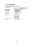
Tensione nominale Vn: 230Vac fase/neutro TT e TN
Tensione di funzionamento: da 0.85 a 1.1 Vn
Durata massima del riarmo: 2 minuti
Intervallo minimo tra due chiusure consecutive: 3 minuti
Tensione di isolamento verso massa: 2500V
Potenza assorbita con interruttore differenziale chiuso: 0 VA
Potenza assorbita con RESTART in blocco: 3 VA
Temperatura d’impiego: da -5°C a +40°C
Le caratteristiche tecniche ed elettriche sono le medesime
dell’interruttore associato.
12
AVVERTENZE PER LA SICUREZZA
N.B. Leggere attentamente prima dell’installazione e dell’utilizzo
del dispositivo
• Intervenire solo ad impianto sezionato e quindi con dispositivo non
inserito.
• Non accedere ai collegamenti elettrici senza aver tolto tensione all’impianto.
• Il prodotto non è idoneo all’installazione in reti fase-fase.
• Quando il dispositivo è in modalità manuale, l’interruttore associato
svolge la funzione di protezione di un interruttore differenziale tradizionale.
• Quando il dispositivo è in modalità automatica svolge un controllo
dell’impianto, in seguito ad apertura dell’interruttore differenziale, per
verificare la possibilità di ripristino automatico in sicurezza.
• Eventuali posizioni intermedie della leva dell’interruttore associato
non costituiscono malfunzionamenti se temporanee.
• Se occorre disalimentare manualmente l’impianto entro tre minuti da
un precedente riarmo automatico agire sul pulsante di test dell’interruttore differenziale previa apertura dello sportello (o sugli interruttori
collegati a valle).
2
INDICE
•
Funzioni di prodotto .......................................................................... 4
•
Descrizioni del prodotto .................................................................... 5
•
Istruzioni per l’uso ............................................................................ 6
- Funzionamento automatico .............................................................. 6
- Inserimento modalità automatica .................................................. 6
- Riarmo automatico........................................................................ 6
- Funzionamento manuale .................................................................. 7
- Da automatico a manuale.............................................................. 7
•
Segnalazione dei led ........................................................................ 8
•
Istruzioni per l’installazione ............................................................ 9
- Montaggio e cablaggio (solo per GW 90 971) ................................ 9
- Installazione .................................................................................. 9
•
Caratteristiche tecniche .................................................................. 11
- Schemi d’installazione.................................................................... 11
3
I
T
A
L
I
A
N
O
FUNZIONI DI PRODOTTO
La funzione di riarmo consiste nella richiusura automatica dell’interruttore
differenziale in caso di sgancio intempestivo per fenomeno elettrico
temporaneo (fulmini, perturbazioni, ecc.)
Prima di procedere all’azione di richiusura il dispositivo effettua un controllo
d’assenza di guasto a terra sul circuito a valle: se viene rilevato un guasto
si porta in stato di blocco altrimenti procede alla richiusura.
Dopo un terzo intervento dell’interruttore differenziale, entro tre
minuti da un precedente riarmo automatico, il dispositivo si porta in
stato di blocco.
Per riabilitare la funzione di riarmo aprire lo sportello, alzare la leva dell’interruttore differenziale in posizione “ I “ e chiudere lo sportello.
Se l’interruttore differenziale non rimane in posizione “ I “, sospendere i
tentativi e chiamare un tecnico specializzato per verificare l’impianto.
Non è possibile attivare la funzione di riarmo ad interruttore differenziale
aperto.
Per attivarla è necessario alzare la leva dell’interruttore differenziale in
posizione “ I ” e chiudere lo sportello. A funzioni attivate il tasto di test e
la leva dell’interruttore differenziale non sono accessibili.
4
DESCRIZIONE DEL PRODOTTO
I
T
A
L
I
A
N
O
Alimentazione
Sinottico Led di
segnalazione
Led di segnalazione
Sportello in posizione
di funzionamento automatico
Alimentazione
Sportello in posizione
di funzionamento
manuale
Leva di riarmo
5
Terminali di
verifica impianto
ISTRUZIONI PER L’USO
FUNZIONAMENTO AUTOMATICO
INSERIMENTO MODALITÀ AUTOMATICA
I
230V
Click!
230V
TEST
0
ON
INSERIRE CON
LEVA IN OFF
POSIZIONE I
ON
I
Alzare la leva.
(Impianto sotto tensione).
INSERIRE CON
LEVA IN OFF
POSIZIONE I
Far scorrere lo sportello fino a sentire lo
scatto (impianto sotto tensione).
RIARMO AUTOMATICO:
- In caso di guasto temporaneo
I
230V
0
TEST
ON
I
TEST
ON
1. Funzionamento normale.
0
230V
0
INSERIRE CON
LEVA IN OFF
POSIZIONE I
INSERIRE CON
LEVA IN OFF
POSIZIONE I
2. Intervento dell’interruttore differenziale.
I
230V
230V
TEST
TEST
0
ON
INSERIRE CON
LEVA IN OFF
POSIZIONE I
ON
I
3. L’apparecchio esegue un test dell’impianto di circa 60sec. (Spia rossa lampeggiante).*
INSERIRE CON
LEVA IN OFF
POSIZIONE I
4. Riarmo eseguito (la leva si rialza ridando
tensione all’impianto, e nei 3 minuti successivi non è azionabile manualmente).
* È possibile forzare manualmente la chiusura dell’interruttore differenziale passando in
modalità manuale ed alzando la leva. Nel caso l’interruttore differenziale scatti nuovamente chiamare l’installatore.
6
- In caso di guasto permanente
I
230V
230V
0
TEST
TEST
0
INSERIRE CON
ON
LEVA IN OFF
POSIZIONE I
ON
I
1. Funzionamento normale.
2. Intervento dell’interruttore differenziale.
230V
0
230V
0
TEST
TEST
0
ON
INSERIRE CON
LEVA IN OFF
POSIZIONE I
0
INSERIRE CON
LEVA IN OFF
POSIZIONE I
ON
3. L’apparecchio esegue un test dell’impianto
di almeno 20sec. (Spia rossa lampeggiante).*
INSERIRE CON
LEVA IN OFF
POSIZIONE I
4. Riarmo non eseguito per problemi all’impianto.
Click!
230V
0
INSERIRE CON
ON
LEVA IN OFF
POSIZIONE I
5. Per sezionare l’impianto aprire lo sportello.
Nota: procedere ad un tentativo di riarmo manuale
aprendo lo sportello ed alzando la leva. In caso di
mancata riattivazione desistere dal continuare l’operazione di riarmo e contattare un tecnico specializzato.
FUNZIONAMENTO MANUALE
DA AUTOMATICO A MANUALE
Click!
230V
230V
ON
I
0
INSERIRE CON
LEVA IN OFF
POSIZIONE I
Far scorrere lo sportello fino a sentire lo
scatto. (Impianto sotto tensione).
ON
INSERIRE CON
LEVA IN OFF
POSIZIONE I
Nel caso si desideri togliere tensione
all’impianto abbassare la leva.
7
I
T
A
L
I
A
N
O
SEGNALAZIONE DEI LED
SEGNALAZIONI
LED
FRONTALE
DISPOSITIVO
CONDIZIONE
Funzionamento manuale
230V
ON
INSERIRE CON
LEVA IN OFF
POSIZIONE I
Dispositivo di riarmo non inserito.
Interruttore differenziale chiuso.
Impianto alimentato.
ON
INSERIRE CON
LEVA IN OFF
POSIZIONE I
Dispositivo di riarmo non inserito.
Interruttore differenziale scattato o aperto
intenzionalmente.
Impianto non alimentato e sezionato.
I
230V
0
Funzionamento automatico
230V
ON
INSERIRE CON
LEVA IN OFF
POSIZIONE I
ON
INSERIRE CON
LEVA IN OFF
POSIZIONE I
ON
INSERIRE CON
LEVA IN OFF
POSIZIONE I
TEST
230V
TEST
rosso
230V
rosso
TEST
Dispositivo di riarmo inserito.
Interruttore differenziale chiuso.
Impianto alimentato.
Dispositivo di riarmo in fase di verifica presenza guasto
o richiusura. L’apertura dello sportello interrompe la
richiusura automatica rendendo possibile la manovra
manuale. Impianto non alimentato ma non sezionato.
Dispositivo di riarmo in blocco per rilevazione guasto
nell’impianto a valle. Tentare un riarmo manuale. Se il tentativo fallisce chiamare l’installatore. Interruttore differenziale scattato. Impianto non alimentato ma non sezionato.
Legenda
Led spento
Led lampeggiante
8
Led acceso
ISTRUZIONI PER L’INSTALLAZIONE
MONTAGGIO E CABLAGGIO (solo per GW 90 971)
INSTALLAZIONE
Prima di effettuare qualsiasi operazione accertarsi che non vi sia tensione
nell’impianto.
Accoppiare RESTART sul lato destro dell’interruttore differenziale SD
facendo particolare attenzione all’inserimento del perno nel foro della
maniglia dell’interruttore differenziale (Fig. 1); spingere per agganciarli
meccanicamente fra loro (Fig. 2). (Il perno e la maniglia devono essere giù).
CLACK !!!
2
Fig. 1
Fig. 2
Installare gli apparecchi sulla
rotaia e collegare i cavi di linea e
carico; prima di serrare i morsetti
collegare i fili d’ingresso del
RESTART lato linea e quelli di
controllo lato carico, inserendo i
capicorda sotto le teste delle viti
(Fig. 3).
LIN
E
LO
AD
Serrare a fondo i morsetti verificando che entrambi i collegamenti siano bloccati.
Fig. 3
9
I
T
A
L
I
A
N
O
ISTRUZIONI PER L’INSTALLAZIONE
A questo punto l’interruttore è
installato correttamente.
È possibile ora chiudere completamente lo sportello solo dopo
aver alzato la leva in posizione “ I “
(Fig. 4).
230V
0
ON
INSERIRE CON
LEVA IN OFF
POSIZIONE I
Fig. 4
Alla prima messa in servizio, far
scattare l’interruttore differenziale
con le apposite strumentazioni di
verifica impianto ed il dispositivo
in funzionamento automatico.
Nel caso il ciclo di riarmo non
venga concluso correttamente
verificare l’isolamento verso terra
dell’impianto, che deve superare i
500kΩ.
I
230V
TEST
ON
I
10
INSERIRE CON
LEVA IN OFF
POSIZIONE I
CARATTERISTICHE TECNICHE
I
T
A
L
I
A
N
O
SCHEMI D’INSTALLAZIONE
RD
Alimentazione dall’alto
kWh
LINE
RD
Id
LOAD
Impianto utente
RD
Alimentazione dal basso
Impianto utente
LINE
RD
Id
LOAD
kWh
11
E N G L I S H
RESTART RD
Series 90
SAFETY WARNINGS
N.B. Read carefully before installing and using the device
• Only intervene with the system sectioned and so with the device not
inserted.
• Do not access the electrical connections without having powered
down the system.
• The product is not suitable for installation in phase-to-phase networks.
• When the device is in manual mode, the associated switch performs
the function of a traditional differential switch.
• When the device is in automatic mode it makes a check of the system,
following the opening of the differential switch, to verify the possibility
of restarting automatically in safety.
• Possible intermediate positions of the lever of the associated switch
are not malfunctions if they are temporary.
• If the system is to be powered down manually within 3 minutes of a
previous automatic restart, use the test button of the differential switch
after opening the hatch (or use the switches connected downstream).
14
INDEX
•
Product functions ............................................................................ 16
•
Product description ........................................................................ 17
•
User instructions ............................................................................ 18
- Automatic operation ...................................................................... 18
- Cutting in automatic mode .......................................................... 18
- Automatic restart ........................................................................ 18
- Manual operation .......................................................................... 19
- From automatic to manual .......................................................... 19
•
Led signals ...................................................................................... 20
•
Installation instructions .................................................................. 21
- Assembly and cabling (only for GW 90 971) ................................ 21
- Installation .................................................................................. 21
•
Technical data ................................................................................ 23
- Installation diagrams...................................................................... 23
15
E
N
G
L
I
S
H
PRODUCT FUNCTIONS
The restart function consists of automatically reclosing the differential
switch if it uncouples unexpectedly due to a temporary electrical
phenomenon (lightning, disturbances, etc.).
Before reclosing, the device makes a check that there is no earthing fault in
the circuit downstream: if there is a fault it goes into locked status,
otherwise it proceeds with reclosing.
After a third cut-in of the differential switch within three minutes of a
previous automatic reset, the device goes into locked status.
To re-enable the restart function, open the hatch, raise the differential
switch lever to position “I” and close the hatch.
If the differential switch will not remain in position “I”, stop trying and
call a specialised technician to check the system.
The restart function cannot be activated when the differential switch is
open; to activate it the differential switch lever must be raised to
position “I” and the hatch closed. The test key and the differential
switch lever cannot be accessed when the functions are active.
16
PRODUCT DESCRIPTION
Power supply
E
N
G
L
I
S
H
Synoptic
signal LED
Signal LED
Hatch in the automatic
operation position
Power supply
Hatch in the manual
operation position
System checking
terminals
Reset lever
17
USER INSTRUCTIONS
AUTOMATIC OPERATION
CUTTING IN AUTOMATIC MODE
Click!
I
230V
230V
TEST
0
ON
INSERIRE CON
LEVA IN OFF
POSIZIONE I
ON
I
Raise the lever.
(System powered up).
INSERIRE CON
LEVA IN OFF
POSIZIONE I
Slide the hatch until a click is heard (system
powered up).
AUTOMATIC RESTART:
- In the case of a temporary fault
I
230V
0
TEST
ON
I
TEST
ON
1. Normal operation.
0
230V
0
INSERIRE CON
LEVA IN OFF
POSIZIONE I
INSERIRE CON
LEVA IN OFF
POSIZIONE I
2. Differential switch cut-in.
I
230V
230V
TEST
TEST
0
ON
INSERIRE CON
LEVA IN OFF
POSIZIONE I
ON
I
3. The device performs a test of the system
of approx. 60sec. (Red indicator blinking).*
INSERIRE CON
LEVA IN OFF
POSIZIONE I
4. Reset completed (the lever rises again,
powering up the system and cannot be
operated manually for the next 3 minutes).
* Differential switch closing can be forced manually by going into manual mode and
raising the lever. Call the installation technician if the differential switch trips again.
18
- In the case of a permanent fault
I
230V
230V
0
TEST
TEST
0
INSERIRE CON
ON
LEVA IN OFF
POSIZIONE I
ON
I
1. Normal operation.
2. Differential switch cut-in.
230V
0
230V
0
TEST
TEST
0
ON
INSERIRE CON
LEVA IN OFF
POSIZIONE I
0
INSERIRE CON
LEVA IN OFF
POSIZIONE I
ON
3. The device performs a test of the system
of at least 20sec. (Red indicator blinking).*
INSERIRE CON
LEVA IN OFF
POSIZIONE I
4. Reset not successful due to system
problems.
Click!
230V
0
ON
INSERIRE CON
LEVA IN OFF
POSIZIONE I
5. Open the hatch to section the system.
Note: attempt a manual reset by opening the hatch
and raising the lever. If the reset fails, stop attempting the reset operation and contact a specialised
technician.
MANUAL OPERATION
FROM AUTOMATIC TO MANUAL
Click!
230V
230V
ON
I
0
INSERIRE CON
LEVA IN OFF
POSIZIONE I
Slide the hatch until a click is heard.
(System powered up).
ON
INSERIRE CON
LEVA IN OFF
POSIZIONE I
Lower the lever if the system is to be
powered down.
19
E
N
G
L
I
S
H
LED SIGNALS
LED SIGNALS
DEVICE FRONT
CONDITION
Manual operation
230V
ON
INSERIRE CON
LEVA IN OFF
POSIZIONE I
Restart device not cut in.
Differential switch closed.
System powered up.
ON
INSERIRE CON
LEVA IN OFF
POSIZIONE I
Restart device not cut in.
Differential switch tripped or opened intentionally.
System disconnected and sectioned.
I
230V
0
Automatic operation
230V
ON
INSERIRE CON
LEVA IN OFF
POSIZIONE I
ON
INSERIRE CON
LEVA IN OFF
POSIZIONE I
ON
INSERIRE CON
LEVA IN OFF
POSIZIONE I
TEST
230V
TEST
red
230V
red
TEST
Restart device cut in.
Differential switch closed.
System powered up.
Restart device in the check for presence of a fault or
reclosing phase. Opening the hatch interrupts automatic
reclosing, making the manual manoeuvre possible.
System disconnected but not sectioned.
Restart device blocked due to a fault in the system downstream. Attempt a manual restart. Call the installation technician if the attempt fails. Differential switch tripped.
System disconnected but not sectioned.
Key
LED off
LED blinking
20
LED on
INSTALLATION INSTRUCTIONS
ASSEMBLY AND CABLING (only for GW 90 971)
INSTALLATION
Ensure that the system is powered down before performing any
operation.
Connect RESTART to the right-hand side of differential switch SD,
taking particular care over inserting the pin into the hole in the
differential switch handle (Fig. 1); push to couple them together
mechanically (Fig. 2). (The pin and the handle must be down).
CLACK !!!
2
Fig. 1
Fig. 2
Install the appliances on the rail
and connect the line and load
cables; before tightening the
terminals connect the RESTART
line side and load side control
input wires, fitting the wire
terminals under the heads of the
screws (Fig. 3).
LIN
E
LO
AD
Fully tighten the terminals,
checking that both connections
are locked.
Fig. 3
21
E
N
G
L
I
S
H
INSTALLATION INSTRUCTIONS
The switch is correctly installed
at this point.
It is now only possible to close
the hatch completely after having
raised the lever to position “I”
(Fig. 4).
230V
0
ON
INSERIRE CON
LEVA IN OFF
POSIZIONE I
Fig. 4
At the first start-up, trip the differential
switch with the special system
checking instrumentation and the
device in automatic mode.
If the reset cycle is not concluded
correctly check the earth insulation of
the system, which must be more than
500kΩ.
I
230V
TEST
ON
I
22
INSERIRE CON
LEVA IN OFF
POSIZIONE I
TECHNICAL DATA
INSTALLATION DIAGRAMS
RD
Power supply from above
kWh
LINE
RD
Id
LOAD
User's system
RD
Power supply from below
User's system
LINE
RD
Id
LOAD
kWh
23
E
N
G
L
I
S
H