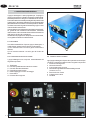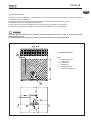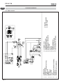
1
GRUPPO ELETTROGENO MANUALE DI USO E MANUTENZIONE
GENSET USE AND MAINTENANCE MANUAL
PD 50 YS
Rev.0 A.A. 29 - 11 - 07
cod.42866
Tipo modello
N° matricola
Codice
I
GB
PD 50 YS
I
INDICE
DEFINIZIONI USATE ................................................. 4
1
4.6
4.7
INFORMAZIONI GENERALI ............................... 6
5
1.1
1.2
1.3
1.4
1.5
1.5.1
1.5.2
1.5.3
1.5.4
1.5.5
1.5.6
Uso conforme .................................................. 6
Rischi residui ................................................... 6
Simbologia sul gruppo elettrogeno ..................... 7
Significato delle etichette di sicurezza ................ 8
Informazioni generali di pericolo ....................... 10
Pericolo di impigliamento ................................ 10
Pericolo di ustioni ......................................... 10
Pericolo di lesioni all’udito ............................... 11
Pericolo di intossicazione ................................ 11
Pericolo di incendio o esplosioni ...................... 11
Pericolo di inosservanza dell’uso dei dispositivi di
protezione del personale ................................. 11
1.5.7 Pericolo causato dall’avvio del motore .............. 12
1.5.8 Pericolo di radiazioni elettromagnetiche ............ 12
1.5.9 Pericolo di folgorazione ................................... 12
1.5.10 Pericolo di cattivo immagazzinamento ............. 12
1.6 Documenti di riferimento ................................. 13
1.7 Conformità alle norme ..................................... 13
1.8 Marcatura ...................................................... 13
1.9 Identificazione della macchina ......................... 13
2
2.1
2.2
2.3
2.4
2.5
CARATTERISTICHEGENERALI ...................... 14
Allestimenti ................................................... 14
Composizione dei gruppi elettrogeni ................. 14
Pannello prese e strumenti .............................. 14
Tabella caratteristiche tecniche ....................... 15
Emissione sonora .......................................... 16
5.1
5.2
6
6.1
6.2
6.3
6.3.1
6.4
6.4.1
6.5
6.6
6.7
6.8
6.9
6.10
7
7.1
8
8.1
8.2
9
3
3.1
3.2
3.2.1
3.2.2
3.2.3
3.3
3.3.1
3.3.2
3.4
3.5
3.6
3.6.1
3.6.2
3.6.3
3.7
3.8
4
4.1
4.2
4.3
4.4
4.5
I -2
Arresto .......................................................... 22
Arresto d'emergenza ..................................... 22
PROTEZIONI E SEGNALAZIONI ...................... 22
Protezione da cortocircuito e sovraccarico .... 22
Protezione motore ........................................ 22
MANUTENZIONE ............................................ 23
Premessa...................................................... 23
Manutenzione ordinaria del motore .................. 23
Cambio olio motore ........................................ 23
Sostituzione filtro olio ...................................... 23
Sostituzione filtro combustibile ........................ 23
Disareazione impianto .................................... 24
Pulizia/sostituzione filtro aria .......................... 24
Controllo liquido refrigerante ............................. 24
Controllo batteria ............................................ 24
Pulizia griglie di aspirazione e scarico .............. 24
Tabella interventi programmati ......................... 25
Periodo di inattività ......................................... 25
ANOMALIE, CAUSE RIMEDI ........................... 26
Norme per l’ordinazione delle parti di ricambio ... 26
GARANZIA, RESPONSABILITA’ ..................... 27
Garanzia ....................................................... 27
Limiti di responsabilità .................................... 27
SMALTIMENTO .............................................. 27
INSTALLAZIONE ............................................ 17
Criteri generali d'installazione ........................... 17
Avvertenze importanti ...................................... 17
Controllo del materiale .................................... 17
Norme di sicurezza gruppi diesel ..................... 17
Fondazioni ..................................................... 17
Impianto di scarico ......................................... 17
Tubazione di scarico ....................................... 17
Dimensionamento delle tubazioni gas di scarico 17
Ventilazione ................................................... 18
Impianto combustibile ..................................... 18
Collegamenti elettrici ...................................... 18
Dimensione cavi di potenza ............................. 18
Sistemazione cavi di potenza .......................... 18
Messa a terra ................................................ 18
Installazione all'esterno ................................. 19
Installazione all'interno .................................. 20
UTILIZZO DEL GENERATORE ......................... 21
Controlli preliminari ......................................... 21
Rifornimento carburante .................................. 21
Batteria ......................................................... 21
Avviamento .................................................... 21
Utilizzo del gruppo elettrogeno ......................... 21
9.1
Smaltimento dei materiali di scarto derivanti dalla
manutenzione, e dalla rottamazione ................. 27
10
SCHEMA ELETTRICI ..................................... 28
10.1 Schema elettrico .......................................... 28
PD 50 YS
I
Questo manuale deve essere conservato per tutta la durata di vita
della macchina a cui fa riferimento
Grazie per aver scelto un prodotto MASE.
Mase Generators è un’azienda leader nel settore dei gruppi elettrogeni ed offre la più vasta gamma di prodotti,
in grado di spaziare dai piccoli generatori portatili da 1 KW fino ad unità da 1600 KVA per applicazioni speciali.
Fondata nel 1970, si sviluppa a Cesena su un’area di 16000 mq. Da sempre si è distinta per l’alta qualità dei
prodotti e per la costante innovazione promossa dall’avanzato Reparto Ricerca e Sviluppo.
Mase Generators nasce come azienda produttrice di gruppi elettrogeni portatili da 500W, leggeri e compatti,
che hanno consentito al suo marchio di essere conosciuto ed apprezzato in tutto il mondo.
Il gruppo elettrogeno che Lei ha acquistato è il frutto di anni di esperienza nel settore, e per la moderna concezione, il robusto dimensionamento, i materiali impiegati, i continui aggiornamenti, costituisce un’efficace
risposta alle esigenze degli operatori del settore.
Questo Manuale istruzioni Le fornirà utili informazioni e preziosi suggerimenti per poter sfruttare appieno
tutte le possibilità che il gruppo elettrogeno Le offre.
Qualora parti del manuale risultassero incomprensibili ci contatti immediatamente.
Nel rinnovarLe i nostri ringraziamenti La salutiamo cordialmente.
MASE GENERATORS SPA
MASE GENERATORS S.p.A. Via Tortona, 345
47023 Cesena (FC) Italy
Tel.+39-0547-354311 Fax.+39-0547-317555
Dati tecnici, informazioni,stesura dei testi ed allestimenti grafici: a cura dell’Ufficio Tecnico Mase Generators
LA DITTA MASE GENERATORS SPA, SI RISERVA TUTTI I DIRITTI SUL PRESENTE MANUALE, NESSUNA
RIPRODUZIONE TOTALE O PARZIALE E’ PERMESSA SENZA AUTORIZZAZIONE SCRITTA DELLA DITTA
MASE GENERATORS SPA.
I
-3
PD 50 YS
I
DEFINIZIONI USATE
- I vocaboli usati sono quelli del linguaggio tecnico corrente e dove si è ritenuto necessario si riportano
di seguito il significato
- Gruppo elettrogeno
E’ l’insieme di un motore a combustione interna a pistoni e un generatore di corrente alternata sincrono 2/4 poli
autoeccitato, uniti tra loro per realizzare una centrale di autoproduzione di energia elettrica.
- Impianto utilizzatore
Impianto costituito dai circuiti di alimentazione degli apparecchi utilizzatori, comprese le relative apparecchiature
di sezionamento, di manovra, di interruzione, di trasformazione, di protezione, ecc. che non facciano parte di
impianti di
produzione, trasmissione e distribuzione.
- Sistema elettrico di I° categoria
E’ un sistema dove la tensione nominale è maggiore di 50 V e minore di 1.000 V compreso in c.a.
- Carico
L’insieme dei valori numerici di grandezze elettriche e meccaniche che caratterizzano le esigenze imposte ad una
macchina rotante da un circuito elettrico o da un dispositivo meccanico, in un determinato istante.
- Interruttore termico
dispositivo generale di sezionamento e interruzione generale costituito da un interruttore ad apertura automatica
per effetto termico.
- Interruttore differenziale
dispositivo generale di sezionamento e interruzione generale costituito da un interruttore ad apertura automatica
per effetto differenziale.
- Persona competente
Persona avente conoscenze tecniche o esperienze sufficienti a consentirgli di evitare i pericoli che può presentare
l’elettricità .
- Personale specializzato MASE
Persona in grado di valutare il lavoro assegnato e riconoscere i possibili pericoli sulla base della formazione,
addestramento presso i centri di formazione MASE, esperienze professionali e conoscenza dell’apparecchiatura
in questione e sui possibili pericoli derivanti in caso di comportamento negligente.
- Fornitore
Entità (per es. costruttore, agente, installatore) che fornisce l’equipaggiamento o i servizi associati alla macchina
- Regolazione
Azione di controllo per cui una variabile di uscita del sistema controllato (variabile regolata) è influenzata da una
variabile di ingresso del sistema regolante per il raggiungimento di un determinato scopo
- Regolazione manuale
Regolazione nella quale la variazione della variabile manipolata viene prodotta dall’uomo con intervento manuale
- Regolazione automatica
Regolazione nella quale la variazione della variabile manipolata viene prodotta da un dispositivo regolante
(regolatore automatico)senza l’intervento dell’uomo
- Protezione
Riparo o dispositivo di protezione come misura di sicurezza per la protezione delle persone da un pericolo presente
o latente.
- Involucro
Parte destinata ad assicurare la protezione dell’equipaggiamento contro specifiche influenze esterne e una
protezione, in ogni direzione, contro i contatti.
I -4
PD 50 YS
I
- Connessione in cattivo stato
Le parti attive non sono completamente ricoperte con un isolamento che possa essere rimosso solo mediante
distruzione, le connessioni presentano una incertezza nel collegamento causata da un labile serraggio delle parti
e da uno sviluppo di ossido fra le parti.
- Contatto diretto
contatto di persone o animali con parti attive
- Circuito di comando
circuito utilizzato per il comando del funzionamento della macchina
- Equipaggiamento
termine generale che comprende materiali, dispositivi, apparecchi, accessori e simili utilizzati congiuntamente
a una installazione elettrica
Indica che è necessario prestare attenzione al fine di non incorrere in serie conseguenze che
potrebbero provocare la morte, o possibili danni alla salute, del personale.
Situazione che potrebbe verificarsi durante il periodo di vita di un prodotto, sistema o impianto
considerato a rischio in materia di danni alle persone, alle proprietà, all’ambiente o di perdite
economiche.
Indica che è necessario prestare attenzione al fine di non incorrere in serie conseguenze che
potrebbero portare al danneggiamento di beni materiali quali le risorse o il prodotto.
Indicazioni di particolare importanza.
Consultare attentamente questo manuale prima di procedere all’uso ed a qualsiasi intervento sulla
macchina.
#
Operazioni di manutenzione periodica, richiedono l'esecuzione da parte di personale qualificato e
dotato di opportuni mezzi di lavoro e di protezione.
I
-5
I
PD 50 YS
1 INFORMAZIONI GENERALI
1.1 USO CONFORME
Il gruppo elettrogeno è adatto a produrre autonomamente energia elettrica nei limiti di tensione e watt dichiarati
dal costruttore.
E’ vietato ogni altro uso al di fuori del campo di impiego già citato: la macchina è destinata ad un uso
industriale.
Il gruppo elettrogeno è stato progettato per lavorare da solo (senza operatore) se non per controlli sporadici.
I limiti di utilizzo sono:
-temperatura di lavoro: -5° +40°
-umidità dell’aria: da 30% a 90%
-la macchina è adatta a lavorare allo scoperto; non può lavorare in ambienti chiusi perchè la macchina produce
gas di scarico.
Solamente Mase o un installatore da essa autorizzato, può confermare l’installazione interna.
Per motivi di sicurezza sono vietate trasformazioni arbitrarie sulla macchina.
Devono essere usati ricambi originali altrimenti decade la conformità della macchina.
Tutte le operazioni che richiedono lo smontaggio di parti speciali devono essere eseguite solamente dal
personale tecnico autorizzato del concessionario locale o della ditta costruttrice.
Solo il personale tecnico della Mase o da essa addestrato possiede la necessaria conoscenza della macchina,
le attrezzature speciali e l’esperienza per eseguire nel modo più economico e affidabile qualsiasi intervento.
1.2 RISCHI
RESIDUI
La macchina è stata progettata tenendo presente le prescrizioni di sicurezza delle direttive e norme CE; occorre
tuttavia tener presente i seguenti pericoli residui:
-
lesioni dovute al contatto di parti calde durante la manutenzione.
lesioni dovute a folgorazione durante la manutenzione del quadro elettrico.
rischi legati a lunghe esposizioni al rumore della macchina.
rischi dovuti al contatto con i liquidi lubrificanti della macchina durante la manutenzione.
rischi dovuti a pericolo di incendio del carburante.
A causa della pericolosità intrinseca tipica dei Gruppi Elettrogeni, si vuole ricordare che, nonostante il gruppo sia
stato progettato, costruito e collaudato secondo quanto stabilito dalle norme antinfortunistiche, soltanto una corretta e attenta utilizzazione può garantire la piena sicurezza; a tale scopo, di seguito sono riportate le varie precauzioni da osservare.
I -6
I
PD 50 YS
1.3 SIMBOLOGIA SUL GRUPPO ELETTROGENO
Cod. 42346
Cod. 42348
cod. 40179
PASSED
cod. 41779
cod. 42118
Cod. 42353
Cod. 42112
Cod. 42352
I
-7
I
PD 50 YS
1.4 Significato delle etichette di sicurezza
• Queste etichette avvertono l’utente su eventuali pericoli che possono causare gravi lesioni.
Leggere attentamente il significato e le precauzioni descritte nel presente manuale
• Se l’etichetta si stacca o diventa illeggibile, sostituirla con una nuova richiedendola ad un rivenditore autorizzato
mase
Simboli di Pericolo
Significato
- Attenzione per evitare ustioni, non toccare durante il funzionamento.
Il collettore di scarico ed il motore, prestare attenzione alle etichette poste sul gruppo
elettrogeno.
- Lasciare che il motore si raffreddi prima di immagazzinarlo all’interno.
- Leggere e comprendere il Manuale d’Uso e Manutenzione prima di azionare il gruppo
elettrogeno.
- Il gruppo elettrogeno mase, è stato progettato in modo da garantire un funzionamento
sicuro ed affidabile, purchè vengano seguite le istruzioni, In caso contrario potrebbero derivarne lesioni personali o danni alle attrezzature.
- l gas di scarico contengono monossido di carbonio, che è tossico.
- Non mettere mai in funzione il gruppo elettrogeno in un ambiente chiuso.
- Provvedere ad un’adeguata ventilazione. Se installato all’interno, osservare scrupolosamente le norme di ventilazione.
STOP
-
I carburanti sono estremamente infiammabili e, in certe condizioni, anche esplosivi.
Effettuare il rifornimento in una zona ben aerata e a motore spento.
Non avvicinare sigarette o scintille mentre si effettua il rifornimento.
Pulire immediatamente eventuali fuoriuscite di benzina.
- Pericolo possibili fuoriuscite di acido corrosivo.
- Pericolo di schiacciamento degli arti superiori.
- Pericolo di scariche elettriche: consultare il manuale.
- Pericolo di scariche elettriche: consultare il manuale.
- Pericolo di ustioni: Superfici calde.
I -8
I
PD 50 YS
Simboli di Obbligo
Significato
- Obbligo collegamento a terra del gruppo elettrogeno.
Simboli di Divieto
Significato
- I collegamenti ad una rete elettrica di emergenza vanno effettuati da elettricisti
specializzati e conformemente alle norme vigenti a riguardo. Collegamenti
impropri possono causare ritorni di corrente dal generatore alle linee elettriche
collegate. Tali ritorni di corrente possono provocare elettroconduzione su coloro
che lavorano per la compagnia elettrica o che entrano in contatto con le linee
durante il guasto. Una volta riabilitata la linea, inoltre, il generatore può esplodere,
bruciarsi oppure causare incendi nel sistema elettrico dello stabile.
- Vietato usare fiamme libere e fumare.
- Divieto di pulire, lubrificare, riparare o registrare ,organi in moto.
- Divieto di spegnere incendi con acqua, utilizzare estintori omologati.
Simboli di Informazione
Significato
- Indica la locazione asta per il controllo del livello dell’olio motore.
- Indica la locazione di un punto di sollevamento del gruppo elettrogeno.
- Indica la locazione del serbatoio carburante per il rifornimento del gruppo elettrogeno.
DIESEL
I
-9
I
PD 50 YS
1.5 INFORMAZIONI
•
•
•
•
GENERALI DI PERICOLO
Sia raccomanda la corretta conoscenza sia della modalità di arresto che di funzionamento di tutti i comandi.
Non lasciare che il gruppo elettrogeno venga utilizzato da personale non qualificato.
Anche se la macchina è protetta, evitare di sostare in prossimità del gruppo elettrogeno.
Non togliere per nessuna ragione le etichette, anzi, richiederne la sostituzione in caso di necessità.
• Prima di mettere in moto il Gruppo Elettrogeno o prima di iniziare qualunque operazione di lubrificazione o
manutenzione, è indispensabile che il personale incaricato abbia letto e compreso tutte le AVVERTENZE ed i
richiami all'ATTENZIONE e PERICOLO riportati in questo manuale e nella ulteriore documentazione tecnica fornita
a corredo.
• Prima di qualsiasi intervento sul gruppo elettrogeno, assicurarsi che il motore primario non sia in funzione e che
non ci siano parti in movimento e collegare un cartellino con la scritta NON AZIONARE o simile, all’interno
dell’interruttore di avviamento o ai comandi prima di eseguire la manutenzione o le riparazioni sulla macchina.
• Il Costruttore non può comunque prevedere tutte le possibili circostanze che possono comportare potenziali rischi
nelle effettive condizioni d'impiego e di uso del Gruppo Elettrogeno.
Le varie operazioni e/o procedure per la manutenzione, non espressamente raccomandate o indicate nei manuali
d'uso, dovranno essere sempre notificate al costruttore a da questi approvate.
Qualora si debba utilizzare un procedimento non specificatamente consigliato sarà cura e responsabilità
dell'utente accertarsi che esso sia sicuro e non rechi danno alle persone.
• Il Costruttore declina ogni responsabilità per danni a persone o cose, conseguenti l’inosservanza delle norme di
sicurezza.
• Esaminare attentamente le targhe segnaletiche di sicurezza applicate sulla macchina e rispettarne le indicazioni
in esse contenute
1.5.1 PERICOLO DI IMPIGLIAMENTO
• Non rimuovere le protezioni originarie su tutte le parti rotanti esposte, sulle superfici calde, sulle prese d'aria, sulle
cinghie, sulle parti in tensione.
• Non intervenire in operazioni di manutenzione a gruppo elettrogeno in moto.
• Non utilizzare indumenti svolazzanti, tipo sciarpe, foulard, bracciali etc. e qualsiasi indumento deve essere chiuso
con elastici agli estremi.
• Non pulire od eseguire manutenzione su parti in movimento.
1.5.2 Pericolo di ustioni
• Non consentire l’uso del gruppo elettrogeno a persone non competenti o senza una adeguata istruzione.
• Non consentire a bambini o animali di avvicinarsi al gruppo elettrogeno in funzione.
• Non toccare mai la marmitta, la relativa protezione o il corpo del motore quando il gruppo elettrogeno è in funzione
od ancora caldo.
• Per nessuna ragione, appoggiarsi o sedersi sul gruppo elettrogeno.
• Individuare la posizione degli estintori o altri dispositivi di protezione ed emergenza e conoscerne il funzionamento.
• Individuare fonti di pericolo quali perdite di combustibile, olio lubrificante, soluzioni acide, condensa nei
gocciolatoi, alte tensioni, pressioni elevate.
• Non provocare corti circuiti appoggiando chiavi od attrezzi sulle batterie o sugli attacchi cavi.
• Il liquido batteria contiene acido solforico, quindi estremamente corrosivo e dannoso per la pelle. Utilizzare sempre
guanti protettivi ed usare estrema cautela nel versare il liquido facendo attenzione a non farlo debordare. In caso
di contatto, lavare abbondantemente la parte colpita con acqua corrente e rivolgersi ad un medico in particolare
se sono interessati gli occhi.
I - 10
I
PD 50 YS
1.5.3 PERICOLO DI LESIONI ALL’UDITO
• Non sostare per periodi prolungati senza cuffie di protezione, si possono avere riduzioni d’udito.
Un esposizione prolungata al di sopra degli 85 dB(A) può provocare disturbi alla salute.
Si consiglia in ogni caso l’utilizzo di appropriati sistemi di protezione (es. cuffie, tappi, ecc..).
1.5.4 PERICOLO
DI INTOSSICAZIONE
• I gas di scarico, contengono ossido di carbonio, gas tossico.
• Non utilizzare mai il gruppo elettrogeno all’interno di gallerie o comunque in locali con poca ventilazione. Qualora
ne sia inevitabile l’uso all’interno, è indispensabile provvedere ad una corretta ed efficace ventilazione al fine di
evitare intossicazioni alle persone o agli animali presenti.
• Verificare che lo scarico dei fumi del motore sia libero e che le tubazioni ne permettano l'evacuazione.
• Verificare che i gas di scarico siano scaricati in atmosfera all'esterno in posizione sicura lontano da porte, finestre
e prese d'aria.
1.5.5 PERICOLO
DI INCENDIO O ESPLOSIONI
• Spegnere sempre il motore prima di effettuare il rifornimento di carburante.
• Non fumare durante i rifornimenti.
• L'operazione di rifornimento carburante va eseguita con estrema cautela avendo cura di non far debordare il
carburante dal serbatoio del motore rispettando il livello massimo.
• In caso di fuoriuscita di carburante dal serbatoio, asciugare e pulire bene le parti interessate.
• Controllare che non vi siano perdite di carburante e che le tubazioni siano integre.
• A rifornimento ultimato chiudere con cura il tappo del serbatoio
• Tenere liquidi infiammabili, fiammiferi ed altri prodotti esplosivi e/o infiammabili lontano dal gruppo elettrogeno,
poichè durante il funzionamento, la temperatura in prossimità della marmitta di scarico è elevata.
• Non lasciare mai liquidi infiammabili o stracci inbevuti di liquido infiammabile in prossimità di apparecchiature
elettriche (incluse le lampade) o parti di impianto elettrico.
• Le batterie sviluppano idrogeno, gas fortemente esplosivo. Si raccomanda di non fumare né provocare scintille
nelle vicinanze, in particolare durante la carica.
• Non ostruire prese / scarichi aria raffreddamento.
• In caso di incendio utilizzare estintore omologato e non utilizzare mai acqua.
1.5.6 PERICOLO DI
•
•
•
•
•
INOSSERVANZA DELL’USO DEI DISPOSITIVI DI PROTEZIONE DEL PERSONALE
Le persone addette alla movimentazione, debbono sempre indossare guanti da lavoro e scarpe antinfortunistiche.
Indossare scarpe antinfortunistiche e tuta.
Qualora il gruppo elettrogeno debba essere sollevato da terra, gli operatori debbono indossare un casco protettivo.
Sostituire immediatamente le tute bagnate.
Usare guanti antinfortunistici.
I
- 11
I
PD 50 YS
1.5.7 PERICOLO CAUSATO DALL’AVVIO DEL MOTORE
• Non lasciare parti smontate sul motore o nelle vicinanze, oppure attrezzi o quant'altro non facente parte dell'impianto.
• Installare le protezioni necessarie per la sicurezza sulle parti di completamento impianto.
• Fare funzionare il gruppo elettrogeno il più possibile su di una superficie piana. Per un funzionamento continuo,
l’inclinazione massima consentita del motore è 20 gradi. Una maggiore inclinazione del gruppo elettrogeno, potrebbe
provocare la fuoriuscita del combustibile o causare problemi alla pressione dell’olio di lubrificazione.
• Per prevenire rischi di incendio e per una corretta ventilazione, posizionare il gruppo elettrogeno durante il funzionamento
ad almeno 1m. (3ft.) da edifici o altre attrezzature.
• Verificare che l’olio sia a livello tramite l’apposita l'astina/livello.
• Verificare che tutte le utenze elettriche siano disinserite per non avviare il gruppo sotto carico.
• Verificare la perfetta funzionalità dei dispositivi preposti all'arresto del gruppo elettrogeno in caso di anomalia per basso
livello olio.
• Individuare la posizione dei pulsanti di arresto di emergenza, interruttori e altri sistemi di emergenza presenti sul gruppo
elettrogeno.
• Conoscere le particolari procedure di emergenza attinenti all'installazione in questione.
1.5.8 PERICOLO DI RADIAZIONI ELETTROMAGNETICHE
• Divieto di accesso alle persone dotate di pace-maker a causa delle possibili interferenze elettromagnetiche sugli
apparecchi cardiocircolatori.
1.5.9
PERICOLO DI FOLGORAZIONE
• Nell’utilizzo del generatore occorre tener presente che nei luoghi bagnati o molto umidi e nei luoghi conduttori ristretti
esiste l’obbligo del rispetto degli articoli 313 e 318 del D.P.R. 27/04/55 NR.547, nonché’ del CAP. 11 SEZ. IV della norma
C.E.I. 64-8.
• Sostituire immediatamente le tute bagnate.
• Isolare tutti i raccordi e fili staccati.
• Non lasciare scoperta la morsettiera di potenza del gruppo elettrogeno, verificare che i collegamenti elettrici di potenza
e dei servizi ausiliari siano eseguiti correttamente.
• Non alimentare carichi aventi tensioni diverse da quelle erogate dal gruppo elettrogeno.
• Non spruzzare acqua direttamente sulle parti elettriche.
• Non pulire con aria compressa le parti elettriche interne, poichè possono verificarsi corto circuiti o altre anomalie.
Non manomettere le protezioni attive, termici, magnetotermici differenziali.
• In caso di anomalie, non rimuovere il pannello per tentare di ripararlo. Rivolgersi al personale specializzato mase.
• Non accedere al generatore con mani bagnate essendo il generatore una potenziale fonte di shock elettrici se mal
utilizzato.
• Prendere precauzioni per evitare il pericolo di folgorazioni; controllare che l'impianto di terra sia presente e realizzato
secondo le Norme.
• Per la sicurezza degli utilizzatori il collegamento a terra del gruppo va sempre eseguito prestando particolare attenzione
alla sezione del cavo da utilizzare. Per il collegamento del cavo di terra utilizzare l'apposito morsetto posto sul gruppo
elettrogeno.
Il costruttore non è responsabile per eventuali danni causati dalla mancata messa a terra dell'impianto.
1.5.10 PERICOLO DI CATTIVO IMMAGAZZINAMENTO
• I gruppi elettrogeni imballati e non, debbono essere depositati in un locale fresco ed aciutto o comunque mai esposto
alle interperie.
• Evitare di impilare più gruppi elettrogeni imballati per non causare cadute di essi provocando danni a cose e/o persone.
I - 12
I
PD 50 YS
1.6 DOCUMENTI DI RIFERIMENTO
1.8 MARCATURA
Le istruzioni per l'uso fornite con ciascun gruppo
elettrogeno sono costituite da una raccolta di documenti
di cui il presente manuale rappresenta la Parte Generale. Normalmente sono forniti i seguenti documenti.
La targa predisposta per i gruppi elettrogeni contiene
tutti i dati identificativi secondo quanto richiesto per la
Marcatura CE, per i casi in cui è prevista. Si riporta qui
il facsimile della targa identificativa che è fissata sul
quadro di controllo di ciascuna macchina.
a Dichiarazione CE di Conformità.
b Manuale di istruzioni per l'uso e la manutenzione
dei gruppi elettrogeni, (il presente manuale).
c Manuale d'uso e manutenzione del motore.
d Elenco Centri Assistenza mase.
e Certificato di garanzia mase.
f Cartolina garanzia.
1.7 CONFORMITÀ ALLE NORME
I gruppi elettrogeni, costruiti dalla ditta mase, destinati
ai paesi della Comunità Europea sono conformi alle
direttive CE applicabili, e sono corredati di una Dichiarazione CE di Conformità.
98/37/CE e successive modifica:
Requisiti essenziali delle macchine, ai fini della sicurezza e della tutela della salute, (Direttiva "Macchine").
Direttiva 2006/95/CE (73/23/CE e successive modifiche contenute nella direttiva 93/68/CE) :
Garanzie di sicurezza che deve possedere il materiale
elettrico destinato ad essere utilizzato entro taluni limiti
di tensione, (Direttive "Bassa Tensione").
2000/14/CE: Direttiva ambientale sull’emissione sonora
(solo nei modelli indicati in tabella emissione sonora).
1.9 IDENTIFICAZIONE DELLA MACCHINA
1
2
3
4
5
6
7
8
9
10
11
12
13
14
15
16
- Nome macchina
- Codice macchina
- Numero di serie
- Potenza continua
- Frequenza dichiarata
- Fattore di potenza
- Tensione nominale
- Corrente nominale
- Grado di protezione
- Classe d’isolamento
- Temperatura max.utilizzo
- Altitudine max.utilizzo
- Classe di prestazione
- Anno di costruzione
- Costruttore - Indirizzo
- Peso
I dati che identificano il numero di codice della
macchina, il numero di serie e l’anno di costruzione devono essere sempre precisati al costruttore
per informazioni, richieste di ricambi, ecc..
1
2
4
Code
Rated power 3F
5
6
7
8
9
10
3
Serial n°
KVA
declared frequency
Hz
Rated power factor
Cos.Ø
Rated voltage
V
V
Rated current
A
A
Degrees of protection
IP
15
Class of insulation
11
12
13
Temp. max of use
°C
Altitude max. of use
m
Performance class
14
year of manifacture
Mass
16
Kg
I
- 13
I
PD 50 YS
2 CARATTERISTICHE GENERALI
Il gruppo elettrogeno è stato progettato per l'impiego in
campo professionale, utilizza motorizzazioni di alta affidabilità del tipo diesel a 3.000 giri con raffreddamento ad aria.
Particolare attenzione è stata posta al grado di protezione da
agenti esterni, alla salvaguardia del motore e alla tutela delle
parti elettriche da sovraccarichi o sovratemperature, adottando sistemi automatici in grado di arrestare il gruppo in caso
di anomalie di funzionamento.
Il gruppo elettrogeno risulta essere particolarmente silenzioso grazie ad una cofanatura insonorizzante, coibentata
internamente, e ad un avanzato sistema d'insonorizzazione
dello scarico dei fumi di combustione.
Gli alternatori impiegati sono del tipo sincrono autoeccitato,
con regolazione elettronica della tensione.
G
F
D
B
F
E
C
A
E
2.1 ALLESTIMENTI
F
Una delle caratteristiche di questo gruppo elettrogeno, è
quella di poter essere fornito in diverse configurazioni:
1) Con marmitta interna e scarico gas di combustione
laterale;
2) Con marmitta esterna e scarico gas dal fondo del
telaio.
E
2.2 COMPOSIZIONE DEI GRUPPI ELETTROGENI
2.3 PANNELLO PRESE E STRUMENTI
I gruppi elettrogeni sono composti essenzialmente dai
seguenti componenti:
Ogni gruppo elettrogeno dispone di un pannello strumenti per i
comandi e i controlli sul quale si trovano i seguenti componenti:
1 Pulsante di emergenza
2 Chiave Avviamento
3 Commutatore rete / gruppo
4 Interruttore magnetotermico differenziale generale
A
B
C
D
E
F
G
Telaio base
Pannello apribile lato manutenzione motore
Pannello fisso lato alternatore
Pannello strumenti e prese
Piede d'appoggio con foro di fissaggio
Presa d'aria
Pulsante di emergenza
1
2
3
7
6
I - 14
(GENERAL SWITCH)
5 Asta livello olio motore
6 Collegamento a terra
7 Contaore
4
5
I
PD 50 YS
2.4 TABELLA CARATTERISTICHE TECNICHE
MODELLO
PD 50 YS
CARATTERISTICHE GENERALI
POTENZA MASSIMA
POTENZA CONTINUA
FATTORE DI POTENZA (Cos Φ)
TENSIONE TRIFASE
TENSIONE MONOFASE
FREQUENZA NOMINALE
GRADO DI PROTEZIONE
TEMP.MAX DI UTILIZZO
TEMP.MIN DI UTILIZZO
ALTITUDINE MAX.DI UTILIZZO
DIMENSIONI
L
W
H
3,4
3
1
/
230
50
IP 23
+40
-5
1000
785
561
637
125
kVA
kVA
V
V
Hz
°C
°C
m
mm
mm
mm
kg
MASSA
MOTORE
TIPO
4 TEMPI
COSTRUTTORE
YANMAR
MODELLO
L70 AE
3
CILINDRATA
296
cm
POTENZA
6,1 - 4,5
CV - kW
n° CILINDRI
1
GIRI
rpm
3000
REGOLATORE DI GIRI
CENTRIFUGO MECCANICO
TIPO DI ASPIRAZIONE
NATURALE
ALIMENTAZIONE
DIESEL
SISTEMA DI INIEZIONE
DIRETTA
CONSUMO CARBURANTE A PIENO CARICO
1,3
L/h
RAFFREDDAMENTO
ARIA
SISTEMA DI LUBRIFICAZIONE
FORZATA
CAPACITA' CARTER OLIO
1,1
L
IMPIANTO ELETTRICO
V
12
MOTORINO AVVIAMENTO
V - kW
12 - 0,8
BATTERIA AVVIAMENTO
V - Ah
12 - 45
CARICA BATTERIA
V-A
12 - 15
SISTEMA DI ARRESTO
ELETTROVALVOLA
ALTERNATORE
TIPO
SINCRONO, 2 POLI, AUTOREGOLATO
CLASSE D'ISOLAMENTO
H
REGOLAZIONE TENSIONE
CONDENSATORE
±10%
STABILITA' DI TENSIONE
STABILITA' DI FREQUENZA
±5%
RAFFREDDAMENTO
ARIA
I valori di stabilità di tensione sono validi per l’uso
di carichi equilibrati. L’utilizzo di carichi squilibrati
può causare variazioni di tensione distruttive per gli
apparati collegati.
Condizioni ambientali di riferimento secondo norma UNI EN ISO 3046/1:
Temperatura 25°C, Pressione 1000 mbar, umidità relativa 30%.
I
- 15
I
PD 50 YS
2.5 EMISSIONE SONORA
I valori riportati sono livelli di emissione e non necessariamente livelli operativi sicuri. Benché vi sia una correlazione tra livelli di emissione e di esposizione, questa
non può essere utilizzata in modo affidabile per stabilire
se siano o meno richieste ulteriori precauzioni. Tra i
fattori che influenzano il livello effettivo di esposizione
della forza lavoro figurano le caratteristiche dell’ambien-
MODELLO
te di lavoro, le altre sorgenti di rumore, quali il numero di
macchine e altri processi adiacenti, e la durata del
tempo di esposizione al rumore di un operatore. Inoltre,
i livelli ammessi di esposizione possono variare da
Paese a Paese. Le presenti informazioni, tuttavia, consentono all’utente della macchina di effettuare una
migliore valutazione del pericolo e del rischio.
PD 50 YS
Livello di potenza acustica garantita LWA
96
dB(A)
In accordo alla Direttiva 2000/14/CE
I rilievi sono stati effettuati a macchina funzionante, ed in accordo alla Direttiva 2000/14/CE; per quanto riguarda il luogo di prova,
le condizioni di misurazione e gli strumenti sono conformi alla ISO 3744 del 1995. Valori di incertezza di misurazione + 1dB.
Livello di pressione acustica
al posto operatore LpA
83
In accordo alla Direttiva 98/37/CE
I rilievi sono stati effettuati a macchina funzionante, ed in accordo alla Direttiva 98/37/CE.
I - 16
dB(A)
I
PD 50 YS
3 INSTALLAZIONE
3.1 CRITERI GENERALI D'INSTALLAZIONE
3.3 IMPIANTO DI SCARICO
L’installazione di uno o più Gruppi elettrogeni deve
essere progettata da tecnici specializzati ed abilitati alla
progettazione di questo tipo di impianti.
L’installazione deve essere realizzata da organizzazioni
abilitate, dotate di personale specializzato e di attrezzature adeguate.
Gli impianti devono essere eseguiti a regola d’arte e
l’impresa installatrice, al termine della realizzazione,
deve rilasciare al Committente una Dichiarazione di
Conformità degli impianti realizzati a Regola dell’Arte, in
riferimento al progetto ed alle norme specifiche.
3.3.1 TUBAZIONE DI SCARICO
3.2 AVVERTENZE IMPORTANTI
Le tubazioni dovranno portare l’uscita del gas in zona dove
non rechi danno o fastidio, lontano da porte, finestre o
prese d’aria e terminare con un sistema fisso di protezione all’ingresso dell’acqua piovana.
Nell’attraversamento di pareti é opportuno provvedere
all’isolamento termico delle tubazioni nel tratto interessato per impedire la trasmissione del calore alle pareti
stesse.
Nella figura sotto illustrata sono riportati alcuni dettagli
sull’argomento accennato.
3.2.1 CONTROLLO DEL MATERIALE
Si consiglia al ricevimento del gruppo, di controllare che
il materiale ricevuto corrisponda a quanto indicato nella
bolla di spedizione che accompagna il gruppo stesso, e
che il materiale non abbia subito danneggiamento,
provvedendo eventualmente all’apertura dei relativi imballi.
Nel caso si riscontrassero avarie, deve essere avvisata
con urgenza la ditta trasportatrice per la denuncia
all’ente assicurativo.
3.2.2 NORME
DI SICUREZZA GRUPPI DIESEL
Il locale e l’installazione del gruppo (fondazione, serbatoio, entrata aria, scarico gas) devono rispondere alle
“Norme di Sicurezza” esistenti nel paese di installazione.
3.2.3 FONDAZIONI (VERSIONE BASE)
La fondazione dovrà essere dimensionata e calcolata
avendo massima cura di evitare la trasmissione di
vibrazioni e rumore alle altre parti della costruzione.
3.3.2 DIMENSIONAMENTO DELLE TUBAZIONI
GAS DI SCARICO
La contropressione allo scarico del motore ha una
notevole influenza sulla potenza resa dallo stesso e sul
suo carico termico. Valori eccessivi della medesima
(misurati all’uscita del collettore di scarico per gli aspirati ed all’uscita turbina per i sovralimentati) provocano
riduzioni della potenza, aumento della temperatura gas
di scarico, fumosità, elevati consumi combustibile,
surriscaldamento dell’acqua di refrigerazione con degrado del lubrificante e relative conseguenze sugli organi
del motore. Le tubazioni dovrebbero essere le più corte
possibili e col minor numero di gomiti.
I
- 17
I
PD 50 YS
3.4 VENTILAZIONE
La ventilazione del locale nel quale é installato il gruppo
elettrogeno é di fondamentale importanza per il buon
comportamento del gruppo stesso.
3.5 IMPIANTO COMBUSTIBILE
Il gruppo non comprende serbatoio interno. Alla base del
telaio sono presenti i fori con i tubi per la mandata (rif.1)
e il ritorno (rif.2) del combustibile (lunghezza 1,8m) da
serbatoio esterno. All'interno del gruppo è presente il
filtro carburante (rif.3).
3
1
3.6 COLLEGAMENTI ELETTRICI
2
L'esecuzione del collegamento elettrico, dovrà essere
eseguito esclusivamente da un installatore tecnico specializzato, seguendo le norme EN 60 204.1 (IEC 204.01).
I gruppi sono già predisposti per essere collegati all’utenza
tramite il pannellino (rif.4).
Il gruppo elettrogeno ha la funzione di sostituire la rete
pubblica e di conseguenza deve essere considerato
come una fonte esterna di energia elettrica. Nell’esecuzione delle connessioni devono essere rispettati i collegamenti indicati negli schemi forniti con il gruppo.
3.6.1 DIMENSIONE CAVI DI POTENZA
La scelta e il dimensionamento dei cavi è competenza
e responsabilità dell’installatore che esegue l’impianto.
AI riguardo evidenziamo che l’impiego di sezioni ridotte
provoca eccessive cadute di tensione e riscaldamenti
dannosi al cavo.
3.6.2 SISTEMAZIONE CAVI DI POTENZA
3
L’insieme dei cavi di collegamento gruppo-utenze per i
gruppi manuali devono essere convenientemente sistemati in idoneo canale o cunicolo.
3.6.3 MESSA A TERRA
Le parti metalliche degli impianti soggette a contatto
delle persone, che per un difetto di isolamento o per altre
cause potrebbero trovarsi sotto tensione, devono essere
collegate ad un dispersore di terra.
I gruppi (sul basamento) ed i quadri sono previsti con
apposito morsetto di messa a terra.
Il dimensionamento del cavo di collegamento al
dispersore di terra e la relativa resistenza di contatto.
Devono essere conformi a Regolamenti e Leggi Vigenti.
N.B.: Gli impianti di terra devono essere il più lontano possibile da linee ferro/tranviarie, per evitare
fenomeni di elettrocorrosione di parti interne del
motore a contatto con acqua.
Non manomettere le protezioni attive, termici,
magnetotermici differenziali.
• In caso di anomalie, non rimuovere il pannello per
tentare di ripararlo. Rivolgersi al personale specializzato mase.
• Prendere precauzioni per evitare il pericolo di
folgorazioni; controllare che l'impianto di terra sia
presente e realizzato secondo le Norme.
• Per la sicurezza degli utilizzatori il collegamento
a terra del gruppo va sempre eseguito prestando
particolare attenzione alla sezione del cavo da
utilizzare. Per il collegamento del cavo di terra
utilizzare l'apposito morsetto posto sul gruppo
elettrogeno.
Il costruttore non è responsabile per eventuali danni
causati dalla mancata messa a terra dell'impianto.
I - 18
I
PD 50 YS
3.7 INSTALLAZIONE ALL’ESTERNO
Per gruppi installati all’esterno si consiglia una posizione tale da permettere la massima protezione da agenti
atmosferici, polvere, ecc.
E' da evitare l’esposizione diretta ai raggi solari che provocano un riscaldamento anormale del complesso.
Si suggerisce di proteggere il gruppo con una tettoia.
Per installazioni provvisorie o comunque di breve durata, é sufficiente l’appoggio del gruppo su terreno ben livellato.
Per installazioni permanenti o comunque di lunga durata é consigliabile la costruzione di una fondazione in cemento.
L’area in cui sarà installato il Gruppo Elettrogeno dovrà essere opportunamente recintata, in modo tale da
impedire l’accesso alle persone non espressamente autorizzate.
È necessario apporre gli appositi cartelli di divieto e di pericolo come previsto dalla normativa vigente.
Installazione all’esterno
Legenda:
1 - Cassa in lamiera verniciata
2 - Quadro elettrico
3 - Fondazione
4 - Cunicolo cavi
5 - Tubo di scarico gas
6 - Rete metallica di protezione
I
- 19
I
PD 50 YS
3.8 INSTALLAZIONE ALL’INTERNO
Per una corretta installazione del gruppo in locale chiuso devono essere rispettate le regole di installazione elencate sotto:
- Il locale deve essere adeguatamente dimensionato in modo da permettere il regolare funzionamento del gruppo nonché
la facile agibilità sia per le operazioni di normale manutenzione che per le eventuali riparazioni. Nella figura sono riportate
le dimensioni minime consigliate relative ai passaggi attorno al gruppo e all’altezza del locale.
- L'accesso al locale deve essere tale da permettere l’introduzione del gruppo completo con i normali mezzi di trasporto
e movimentazione disponibili in loco.
- Devono essere presenti aperture di adeguate dimensioni per permettere un continuo ed efficiente ricircolo di aria.
- E' obbligatorio l' installazione di una tubazione di scarico all'esterno di lunghezza ridotta e con il minore numero di curve.
- E' possibile sistemare il gruppo con sufficiente spazio di passaggio su almeno tre Iati, pur mantenendo una facile agibilità
e il rispetto delle norme di sicurezza.
- Il quadro di comando (nel caso di gruppo automatico) deve essere posizionato in modo tale da avere gli strumenti ben
visibili all'operatore che si trova in prossimità del gruppo (come esempio vedi figura sotto).
Montaggio all’interno
Legenda:
1 - Cassa in lamiera verniciata
2 - Quadro elettrico
3 - Fondazione
4 - Cunicolo cavi
5 - Ingresso aria
6 - Tubo di scarico gas
7 - Uscita aria tramite elettroventilatore
I - 20
I
PD 50 YS
4 UTILIZZO DEL GENERATORE
4.1 CONTROLLI PRELIMINARI
Prima di iniziare qualsiasi procedura di avviamento è
estremamente importante "familiarizzare" con il gruppo
elettrogeno e i suoi comandi. Si dovrà inoltre eseguire un
controllo di sicurezza visivo della macchina e dell'installazione.
Qualsiasi fonte di pericolo reale o potenziale deve
essere eliminata prima di procedere.
• Individuare la posizione dei pulsanti di arresto di
emergenza, interruttori e altri sistemi di emergenza
presenti sul gruppo elettrogeno.
• Conoscere le particolari procedure di emergenza attinenti all'installazione in questione.
• Individuare la posizione degli estintori o altri dispositivi
di protezione ed emergenza e conoscerne il funzionamento.
• Individuare fonti di pericolo quali perdite di combustibile, olio lubrificante, soluzioni acide, condensa nei
gocciolatoi, alte tensioni, pressioni elevate.
• Assicurarsi che il gruppo elettrogeno sia pulito, che le
zone circostanti siano pulite e prive di ostacoli.
• Controllare che non vi siano ostruzioni nelle aperture e
condotte di ventilazione.
• Che il tubo di scarico fumi non sia orientato contro
ostacoli o almeno che questi si trovino ad almeno due
metri da esso.
• Che il collegamento a terra del gruppo elettrogeno sia
stato correttamente eseguito.
Al primo avviamento del gruppo, dopo aver eseguito un
qualsiasi intervento di manutenzione, è buona norma
accertarsi sempre:
- che l’olio sia a livello tramite l’astina (paragrafo
"manutenzione");
- che tutte le utenze elettriche siano disinserite per non
avviare il gruppo sotto carico;
- che le tubazioni del combustibile siano integre e
correttamente collegate;
- che non vi siano connessioni elettriche in cattivo
stato.
4.2 BATTERIA
Il gruppo elettrogeno è fornito con batteria priva di acido
(rif.1).
Il liquido batteria è acido corrosivo
estremamente dannoso per la pelle.
Non provocare corti circuiti appoggiando chiavi od
attrezzi sulle batterie o sugli attacchi cavi.
Fare attivare la batteria da personale
che disponga di acido solforico per batterie e delle
idonee attrezzature.
- Non scollegare le batterie col gruppo elettrogeno
funzionante; l'alternatore carica batteria e le apparecchiature elettroniche potrebbero danneggiarsi irreparabilmente.
- Rispettare la polarità + / - nel collegamento, in quanto
il mancato rispetto causerà, all'avviamento, un corto
circuito che danneggerà irrimediabilmente le
apparecchiature elettroniche.
I morsetti e le connessioni devono
essere sempre mantenuti asciutti e puliti; per evitare
ossidazioni, pulire e ricoprire i morsetti con un velo di
grasso di vaselina.
1
4.3 AVVIAMENTO
Verificare, prima di procedere all’avviamento del gruppo
elettrogeno, che tutte le utenze siano disinserite, evitando in
tal modo di mettere sotto sforzo il motore ancora freddo.
Procedere all’avviamento ruotando in senso orario la chiave
dello START (rif.1) di uno scatto (posizione ON). Ruotare
quindi la chiave di accensione su START e rilasciare solo ad
avviamento avvenuto. Non superare in ogni caso, più di 5
secondi ad ogni tentativo. Tutte le protezioni verranno attivate
con l'avviamento del gruppo elettrogeno, ed in caso di
anomalie di funzionamento, il gruppo elettrogeno verrà
arrestato.
4.4 UTILIZZO DEL GRUPPO ELETTROGENO
Prima di alimentare gli utilizzi è bene lasciar funzionare,
senza carico applicato, il motore per almeno cinque
minuti permettendogli di raggiungere progressivamente
la temperatura di lavoro. Tale accorgimento, garantirà
una maggiore durata del motore ed eliminerà il rischio di
grippaggi.
La potenza disponibile è quella indicata sull'adesivo
caratteristiche tecniche apposta sulla macchina e nel
dettaglio della tab caratteristiche tecniche par. 2.4.
I
- 21
PD 50 YS
5 PROTEZIONI E SEGNALAZIONI
ON
STOP
START
I gruppi elettrogeni sono dotati di una serie di protezioni
che li salvaguardano da un utilizzo non corretto e da
inconvenienti che ne possono pregiudicare l'integrità.
1
5.1 PROTEZIONE DA CORTOCIRCUITO E SOVRACCARICO
La somma degli assorbimenti degli utilizzi collegati
al gruppo elettrogeno non deve mai superare il
valore della potenza continuativa di questo.
4.6 ARRESTO
Il gruppo elettrogeno si arresta ruotando completamente in senso antiorario la chiave di accensione in posizione di STOP.
Prima di arrestarlo si consiglia di farlo funzionare, per
alcuni minuti, senza carichi inseriti permettendo, in tal
modo, di ridurre gradualmente le temperature interne del
motore e dell’alternatore.
4.7 ARRESTO D’EMERGENZA
Per l’arresto di emergenza del gruppo in moto, agire sul
pulsante di arresto di emergenza "a fungo".
Eliminate le cause che hanno determinato la necessità di un
arresto di emergenza, per tornare in condizioni operative,
occorre sbloccare il pulsante di arresto di emergenza.
E RG E N
CY
EM
I
S TOP
I - 22
Vedi par.2.3 "Pannello prese strumenti"
Per una protezione da cortocircuiti e sovraccarichi, il
gruppo è dotato di interruttori magnetotermici e interruttori differenziali, i quali intervengono, interrompendo l'erogazione della corrente, qualora si dovesse
verificare una condizione di sovraccarico all'alternatore o un cortocircuito. Prima di ripristinare l'erogazione
della corrente, riportare la leva del magnetotermico in
posizione 'ON'; è necessario rimuovere la causa che
ne ha provocato l'intervento.
Un'interruttore magnetotermico differenziale generale
ha il compito d' interrompere l'erogazione della corrente
a tutte le prese in caso di cortocircuito, sovraccarico e
dispersione di corrente verso terra.
5.2 PROTEZIONE MOTORE
Nel caso in cui si verifichi una insufficiente pressione
dell'olio motore, il gruppo si pegne automaticamente.
Reintegrare la quantità di olio mancante per poter riavviare
il gruppo elettrogeno.
La protezione bassa pressione olio non da un’indicazione sul livello dell’olio. Un controllo periodico del livello
olio è indispensabile al fine di evitare danni al motore.
I
PD 50 YS
6 MANUTENZIONE
6.1 PREMESSA
Qualsiasi intervento di manutenzione al gruppo elettrogeno va effettuato a motore
spento , dopo averlo lasciato raffreddare a sufficienza.
Leggere attentamente nel manuale il paragrafo 1.5
(informazioni generali di pericolo). Verificare periodicamente le sicurezze elettriche alla persona, come
l'emergenza, l'impianto di terra ecc.
Prima di qualsiasi operazione di
manutenzione, spegnere il gruppo elettrogeno togliendo la chiave di accensione dal quadro elettrico.
Si raccomanda di seguire scrupolosamente le indicazioni
riportate sul manuale fornito dal Costruttore del motore,
allegato ad ogni gruppo.
E' importante controllare ed eseguire la manutenzione del
gruppo elettrogeno regolarmente e gli interventi devono
essere decisi in base alle ore di funzionamento.
6.2 MANUTENZIONE ORDINARIA DEL MOTORE
- Proteggere le mani dal contatto con olio proteggendole
con guanti. In caso di contatto accidentale con olio
motore, lavare accuratamente la parte interessata con
acqua e sapone.
- Durante le operazioni di rabbocco e rifornimento d'olio
rispettare il riferimento di livello massimo.
Una quantità eccessiva di olio motore può causare danni
al motore.
6.3.1 SOSTITUZIONE FILTRO OLIO
- Svitare il filtro olio e rimuoverlo (rif.5)
- Per lavare la cartuccia del filtro usare usare benzina o
gasolio.
6.4 SOSTITUZIONE FILTRO COMBUSTIBILE
Tale operazione si esegue tramite i seguenti passaggi:
- svuotare completamente il serbatoio del combustibile
- rimuovere le fascette (rif.6).
- rimuovere la vecchia cartuccia (rif.7) e posizionare la
nuova.
- per il rimontaggio ripetere le operazioni con sequenza
inversa.
Gli interventi periodici, da effettuare sul motore, sono
indicati sulla tabella riportata al punto 6.9. Per informazioni più dettagliate consultare il manuale fornito dal
Costruttore del motore, allegato ad ogni gruppo.
Controllare quotidianamente il li-
1
vello dell’olio tramite l’apposita astina graduata (rif.1).
Il livello dell’olio deve sempre essere compreso tra le
tacche di MAX e MIN incise sull’astina.
6.3 CAMBIO OLIO MOTORE
Vedi il libretto specifico del motore.
Utilizzare olio per motori diesel.
I rabbocchi e i caricamenti vanno eseguiti attraverso il foro
indicato alla (rif.1).
Per informazioni dettagliate a riguardo consultare il manuale uso e manutenzione del motore che accompagna
la macchina. Per la sostituzione dell’olio nel carter motore
si procede togliendo il tappo (rif.1), che serve per facilitare
l'estrazione olio. Inserire il tubo in gomma (rif.2) nel
l'apposito foro sul telaio (rif.3). Svitare il tappo del tubo
in gomma (rif.4) e fare defluire l'olio. Si consiglia di
eseguire lo svuotamento con olio ancora sufficientemente
caldo in modo da consentire un agevole deflusso.
6
2
7
1
6
5
3
Non disperdere nell'ambiente l'olio
esausto in quanto prodotto inquinante.
Consegnare l'olio lubrificante esausto presso gli appositi Centri di Raccolta incaricati dello smaltimento.
4
2
I
- 23
I
PD 50 YS
A sostituzione avvenuta è necessario disareare l'impianto di alimentazione eseguendo le operazioni descritte al
paragrafo 6.4.1 "primo avviamento".
Non portare a contatto della pelle
il carburante. Durante le operazioni di manutenzione
usare guanti e occhiali protettivi.
In caso di contatto con carburante lavare immediatamente e accuratamente la parte con acqua e sapone.
Ad operazione ultimata pulire accuratamente tutte le tracce di carburante e versare gli
stracci utilizzati presso gli appositi Centri di Raccolta
6.4.1 DISAREAZIONE IMPIANTO
La presenza di bolle d’aria, all’interno dell’impianto di alimentazione, è la causa del funzionamento irregolare del motore
o l’incapacità di raggiungere il numero di giri nominale.
L’aria può penetrare all’interno del circuito di alimentazione attraverso una giunzione non perfettamente a
tenuta (tubazione, filtri, serbatoio) o quando il carburante all’interno del serbatoio è al livello minimo. Per
eliminare le bolle d’aria all’interno del circuito di alimentazione è necessario, prima di tutto, rimuovere la causa
che ne ha permesso l’entrata.
Agire manualmente eseguendo, a motore spento, le
seguenti operazioni:
1 - Allentare la vite di sfiato (rif.5).
2 - Far defluire il carburante in un contenitore fino a
quando l’aria contenuta all’interno del filtro (rif.4)
non è fuoriuscita tutta dalla vite di sfiato.
3 - Serrare la vite di sfiato ed avviare il motore.
6.7 CONTROLLO BATTERIA
La batteria necessita esclusivamente di un controllo
periodico del livello dell'elettrolito e per un eventuale
rabbocco utilizzare solo acqua distillata.
Normalmente il livello dell'acido deve trovarsi entro le
linee di livello riportate sul corpo della batteria.
Quando raggiunge il livello MIN fare il rabbocco, con
acqua distillata, degli elementi facendo attenzione a non
superare il livello MAX indicato sul corpo della batteria.
Le batterie sviluppano un gas fortemente esplosivo. Si
raccomanda di non fumare nè provocare scintille nelle
vicinanze, e in particolare durante la carica.
Indossare gli occhiali protettivi. Per smontare la batteria,
scollegare prima il cavo negativo (-) . Quando si rimonta
collegare prima il cavo positivo (+)
6.8 PULIZIA GRIGLIE DI
Controllare sempre la pulizia delle griglie di aspirazione
e scarico aria.
Queste devono restare libere da elementi che ostruiscono il regolare flusso dell'aria di raffreddamento (foglie,
carta, stracci, ecc.).
5
4
6.5 PULIZIA/SOSTITUZIONE FILTRO ARIA
Per un corretto funzionamento, ed una lunga durata del
motore, è importante pulire periodicamente il filtro aria.
Un filtro non efficiente può essere la causa di perdita di
potenza del motore e di eccessiva fumosità allo scarico.
Per pulire il filtro aria eseguire le seguenti operazioni:
- Togliere il coperchio (rif.1) dal portafiltro, svitando la
vite a farfalla (rif.2);
- pulire il filtro (rif.3) e, se necessario, sostituirlo;
- fissare il filtro;
- rimontare il coperchio (rif.1) e fissarlo con la vite a
farfalla esterna (rif.2).
Durante l'operazione di pulizia prestare le seguenti
avvertenze:
- non battere mai la cartuccia per la rimozione di sporco,
ma utilizzare aria compressa asciutta, dall'interno
verso l'esterno, ad una pressione di MAX 2 bar;
- illuminare la parte interna della cartuccia per vericarne
lo stato, e se presenta lacerazioni o fori sostituirla.
Sostituire mediamente la cartuccia filtro aria ogni 3
I - 24pulizie.
ASPIRAZIONE E SCARICO
1
2
3
I
PD 50 YS
6.9 TABELLA INTERVENTI PROGRAMMATI
6.10 PERIODO DI INATTIVITÀ
Controlli eseguibili sia dall'officina autorizzata che dall'utente della macchina
Se il gruppo deve rimanere inutilizzato per un lungo
periodo è necessario eseguire le seguenti operazioni.
CONTROLLI
Controllare il livello del combustibile e riempire
Controllo livello olio nella coppa
Controllare che non ci siano perdite di combustibile
Controllo intasamento filtro aria (1)
Controllare che non ci siano perdite di olio
Controllo livello elettrolita delle batterie (1) (2)
CADENZA
ogni giorno
ogni giorno
ogni giorno
200 ore
ogni giorno
ogni giorno
Operazioni di manutenzione periodica da parte di personale qualificato dotato di opportuni mezzi di lavoro e
protezione
MANUTENZIONE PERIODICA #
Sostituzione filtro aria (2)
Sostituzione olio nella coppa (4 - 5 - 6)
Sostituzione filtro olio (2 - 4)
Sostituzione filtro combustibile (2)
Regolazione gioco valvole-bilancere (2)
Taratura iniettori (2)
•
•
•
•
Svuotare il serbatoio carburante.
Sostituire l’olio motore.
Pulire il filtro aria.
Scollegare i cavi della batteria. Consigliamo di ricaricare
mensilmente la batteria, così da evitare la scarica
totale della stessa che, a volte, ne compromette
l'integrità.
• Pulire esternamente il gruppo elettrogeno rimuovendo
polvere e impurità.
• Ricoprire il gruppo elettrogeno con telo di nylon e
immagazzinare, posizionandolo in orizzontale, in luoghi asciutti e ventilati.
CADENZA
400 ore
200 ore
400 ore
400 ore (3)
400 ore
400 ore
(1) = La cadenza varia in funzione dell’impiego e delle
condizioni ambientali in cui opera il motore
(2) = Queste operazioni, debbono essere effettuate
ogni 6 mesi anche nel caso in cui non vengano
raggiunte le ore di funzionamento previste.
(3) = Periodo massimo, con combustibile di buona
qualità; può variare in dipendenza della
contaminazione del combustibile.
(4) = Sostituire dopo le prime 50 ore di funzionamento
(rodaggio).
(5) = In caso di utilizzo del combustibile con percentuale
di zolfo superiore allo 0,5%, la cadenza di
sostituzione dell’olio motore deve essere
dimezzata.
(6) = Queste operazioni, debbono essere effettuate
ogni 3 mesi anche nel caso in cui non vengano
raggiunte le ore di funzionamento previste.
I
- 25
I
PD 50 YS
7 ANOMALIE, CAUSE RIMEDI
Il gruppo elettrogeno, all'avviamento, non parte ed il motorino di avviamento non da alcun segnale.
• Controllare lo stato di carica della batteria. Ricaricare
• Controllare il blocco chiave. Consultare Centro Assistenza.
• Controllare il motorino avviamento. Consultare Centro Assistenza.
Il motorino di avviamento gira ma il motore principale non si avvia.
• Verificare la presenza di carburante all’interno del serbatoio. Rifornire.
• Verificare se l’elettrovalvola di stop è alimentata. Consultare Centro Assistenza.
• Verificare che non sia inserito il pulsante d'arresto d'emergenza. Se inserito ruotarlo per disinserirlo.
Il gruppo si spegne durante il periodo di lavoro.
• Controllare la presenza di carburante nel serbatoio. Ripristinare il livello.
• Verificare se è stata attivata la protezione basso livello olio; controllare il livello e se basso aggiungere l'olio
necessario per ripristinale il corretto livello. Non ci sono spie di segnalazione; è necessario sempre un controllo
visivo.
Il motore funziona in maniera irregolare.
• Controllare i filtri del carburante. Sostituire.
• Controllare il funzionamento della pompa iniezione. Consultare un Centro Assistenza Autorizzato.
• Controllare la taratura degli iniettori. Consultare un Centro Assistenza Autorizzato.
Il motore ha un'alta fumosità dallo scarico.
• Controllare il filtro aria. Pulire gli elementi che lo compongono o, se necessario, sostituirli.
• Controllare che il livello dell'olio non superi l'indicazione di MAX. Ripristinare il corretto livello.
Batteria di avviamento scarica.
• Controllare il livello dell'elettrolito all'interno della batteria. Ripristinare il livello.
• Controllare il dispositivo di ricarica batteria. Consultare un Centro Assistenza Autorizzato.
• Controllare l'integrità della batteria.
Il gruppo elettrogeno non eroga tensione alle prese e il voltmetro non indica presenza di tensione.
• Controllare che l'interruttore differenziale magnetotermico, o un magnetotermico, sia in posizione ON.
• Probabile guasto all'alternatore. Consultare un Centro Assistenza.
7.1 NORME PER L’ORDINAZIONE DELLE PARTI DI RICAMBIO
Per assicurare un buon funzionamento del gruppo elettrogeno, si raccomanda di utilizzare solo ricambi originali.
Tali ricambi possono essere acquistati presso la rete assistenza autorizzata MASE (consultare il manuale
SERVICE allegato al gruppo elettrogeno).
Per EVENTUALI ULTERIORI informazioni è inoltre possibile contattare il Service centrale MASE.
I - 26
I
PD 50 YS
8 GARANZIA, RESPONSABILITA’
8.1 GARANZIA
• I Gruppi elettrogeni MASE, e tutti i suoi componenti sono garantiti privi di difetti, e sono coperti da garanzia per
il periodo di 2 anni a partire dalla data di installazione.
• Non coperti da garanzia: mancata osservanza delle norme d’installazione, danni dovuti a disastri naturali,
incidenti, difetti dell’impianto elettrico compreso il carico a cui il gruppo è connesso, negligenza, uso improprio
o abuso causato dall’operatore e danni causati da riparazioni effettuate da personale non specializzato.
• Le riparazioni che non sarà possibile eseguire sul luogo di installazione potranno essere eseguite nei laboratori
della MASE o presso le officine autorizzate. Le spese di trasporto saranno a carico del Cliente.
• In nessun caso il Cliente avrà diritto di reclamare risarcimenti per danni o effetti collaterali occorsi a causa
dell’utilizzo della macchina in maniera non conforme a quanto riportato in questo manuale.
8.2 LIMITI DI RESPONSABILITÀ
MASE GENERATORS S.p.A si ritiene responsabile per quanto concerne la sicurezza, l’affidabilità e le prestazioni
del Gruppo a patto che:
• L’uso sia da parte di persone precedentemente istruite da libretto uso e manutenzione.
• L’installazione sia eseguita come da istruzione MASE.
• Le procedure di assistenza siano eseguite esclusivamente da personale tecnico specializzato MASE.
• L’impianto elettrico ed i carichi a cui è collegato il Gruppo siano in conformità con le norme CEI applicabili.
• Il Gruppo sia installato e utilizzato in accordo con le installazioni fornite nel presente manuale.
• Si utilizzino ricambi originali e specifici per ogni modello.
• Si utilizzi il carburante idoneo.
9 SMALTIMENTO
9.1 SMALTIMENTO DEI MATERIALI DI SCARTO DERIVANTI DALLA MANUTENZIONE E DALLA ROTTAMAZIONE
• L’imballo utilizzato nel trasporto è biodegradabile, e quindi facilmente smaltibile da ditte autorizzate alla raccolta
della carta .
• La componentistica elettrica deve essere affidata a ditte autorizzate alla raccolta di materiale elettronico.
• Tutte le parti metalliche verniciate devono essere affidate a ditte autorizzate alla raccolta dei metalli.
Si segnala che nel gruppo e nei suoi componenti sono presenti materiali che, se dispersi nell’ambiente,
possono creare rilevanti danni ecologici.
I seguenti materiali devono essere consegnati ad appositi centri di raccolta autorizzati per lo smaltimento:
- Batterie di avviamento;
- Oli di lubrificazione esausti;
- Miscele di acqua e antigelo;
- Filtri;
- Materiale ausiliario per la pulizia (ad es.: stracci unti o imbevuti di combustibile e/o di prodotti chimici
per la pulizia).
• Tutto il resto del materiale sopra non elencato, deve essere consegnato a ditte autorizzate alla raccolta di rifiuti
industriali.
I
- 27
1
2
3
4
5
6
7
8
9
10
I - 28
ALTERNATORE
CONTAORE
ALTERNATORE VOLANO RIC.BATTERIA
BATTERIA
CHIAVE ACCENSIONE
CONDENSATORE
FUSIBILE
MAGNETOTERMICO-DIFFERENZIALE 2P
MODULO PROTEZIONE MOTORE
MOTORINO DI AVVIAMENTO
21
11
12
13
14
15
16
17
18
PRESSOSTATO OLIO
PULSANTE ARRESTO DI EMERGENZA
REGOLATORE CAR.BATTERIA
RELE START
ROTORE
STATORE
TERMOSTATO MOTORE
ELETTROVALVOLA INTERCETTAZIONE
CARBURANTE
19
20
21
22
VITE COLLEGAMENTO A TERRA
COMMUTATORE
MORSETTIERA
POMPA COMBUSTIBILE
I
PD 50 YS
10 SCHEMI ELETTRICI
10.1 SCHEMA ELETTRICO
PD 50 YS
INDEX
GB
DEFINITIONS USED ................................................ 4
1
GENERAL INFORMATIONS ............................ 6
1.1
1.2
1.3
1.4
1.5
1.5.1
1.5.2
1.5.3
1.5.4
1.5.5
1.5.6
Conform use ................................................... 6
Residual risks ................................................. 6
Symbols on the generator group ..................... 7
Position of safety labels .................................. 8
General danger information ........................... 10
Danger of entanglement ................................ 10
Danger of burns ............................................ 10
Danger of harm to hearing ............................. 11
Danger of intoxication ................................... 11
Danger of fire or explosion ............................ 11
Danger if failing to use personal protection
devices ......................................................... 11
1.5.7 Danger caused by the engine starting ........... 12
1.5.8 Danger of electromagnetic radiation .............. 12
1.5.9 Danger of electrocution ................................. 12
1.5.10 Danger resulting from bad storage ............... 12
1.6 Reference documents ................................... 13
1.7 Reference regulations and legislative provisions . 13
1.8 Marking ........................................................ 13
1.9 Identification of the generator unit ................. 13
2
2.1
2.2
2.3
2.4
2.5
3
3.1
3.2
3.2.1
3.2.2
3.2.3
3.3
3.3.1
3.3.2
3.4
3.5
3.6
3.6.1
3.6.2
3.6.3
3.7
3.8
4
4.1
4.2
4.3
4.4
4.5
GB - 2
GENERAL CHARACTERISTICS .................... 14
Configurations ............................................... 14
Composition of generator unit ....................... 14
Instrument panel ........................................... 14
Table of technical characteristics .................. 15
Noise emission ............................................. 16
INSTALLATION ............................................. 17
General installation criteria ........................... 17
Important information .................................... 17
Inspection of materials .................................. 17
Safety standards for diesel engines .............. 17
Foundations ................................................. 17
Exhaust plant ............................................... 17
Exhaust pipe ................................................ 17
Exhaust pipe design ..................................... 17
Ventilation .................................................... 18
Fuel system ................................................. 18
Electrical connection .................................... 18
Power Cable sizes ........................................ 18
Power cable layng ........................................ 18
Earthing ........................................................ 18
Outdoor installation ....................................... 19
Indoor installation ......................................... 20
USING THE GENERATOR ............................. 21
Preliminary checks ....................................... 21
Refuelling ...................................................... 21
Battery ......................................................... 21
Starting ........................................................ 21
Using the generator ...................................... 21
4.6
4.7
5
5.1
5.2
6
6.1
6.2
6.3
6.3.1
6.4
6.4.1
6.5
6.6
6.7
6.8
6.9
6.10
6.11
7
7.1
8
8.1
8.2
9
Stopping ....................................................... 22
Emergency stop ........................................... 22
PROTECTIONS AND WARNING SIGNALS .. 22
Protection against short-circuit and overload . 22
Engine protection module ............................. 22
MAINTENANCE ............................................. 23
Preamble ...................................................... 23
Ordinary engine maintenance ....................... 23
Engine oil change ......................................... 23
Changing oil filter .......................................... 23
Changing fuel filter ....................................... 23
System bleeding ........................................... 24
Air filter cleaning/replacement ....................... 24
Coolant check .............................................. 24
Battery check ............................................... 24
Suction grid and vent cleaning ...................... 24
Scheduled maintenance table ....................... 24
Period of inactivity ........................................ 25
Wiring diagram list ........................................ 25
ANOMALIES, CAUSES AND REMEDIES ...... 26
How to order the spare sparts ....................... 26
GUARANTEE AND RESPONSIBILITY ........... 27
Guarantee .................................................... 27
Limits of responsibility .................................. 27
DISPOSAL .................................................... 27
9.1
Disposal of the waste materials deriving from
maintenance and scrapping .......................... 27
10
WIRING DIAGRAMS ..................................... 28
10.1 Wiring diagram ............................................. 28
PD 50 YS
GB
This manual has to be preserved for all through life of the
gen set to which ago reference
Thank you for having chosen a product MASE.
As a leading generator manufacturer, Mase Generators offers a wide range of generators with an output from 1 KVA
portable generators to 1600 KVA units for special applications.
Founded in 1970, the Cesena-based company extends over a area of 16,000 square meters, including a 9,000 sq. mtr.
manufacturing facility.
Mase Generators began as a company producing 500 Watt, light and compact portable generators. These generators
made the Mase Generators name well known throughout the world. Mase Generators is a leader in high
quality, reliable products, and innovative research performed by Research and Development Department.
The generator you have purchased is the fruit of years of experience in the sector and for the modern conception, the
strong sizing, the materials employees, the continuous updatings, constitutes an effective answer to the operators’
demands of the sector.
This Manual instructions will furnish you useful information and precious suggestions so you can fully exploit
all the possibilities that the generators offers you.
If any part of the manual resulted incomprehensible, please contact us.
In to renew our thanks we cordially greet you.
MASE GENERATORS SPA
MASE GENERATORS S.p.A. Via Tortona, 345
47023 Cesena (FC) Italy
Tel.+39-0547-354311 Fax.+39-0547-317555
Technical data, informations, layouts of the texts and graphic preparations: edited by the Technical Office
Mase Generators
THE MASE GENERATORS SPA, RESERVES ALL THE RIGHTS ON THE MANUAL PRESENT. ANY TOTAL
OR PARTIAL REPRODUCTION IS PERMITTED WITHOUT WRITTEN AUTHORIZATION OF THE MASE
GENERATORS SPA.
GB
-3
PD 50 YS
GB
DEFINITIONS USED
- The terms used are current technical terms, and where considered necessary the meaning is described below
- Generator
An assembly of an internal combustion piston engine and an alternate current, synchronous, 2-4 pole, self-excited
generator, joined together to create a station for self-production of electrical energy.
- User system
Composed of the power supply circuits of the user equipment, including the relevant sectioning, handling,
breaking, transformation, protection, etc. devices which do not form part of the
production, transmission and distribution systems.
- Category 1 electrical system
A system where the rated voltage is greater than 50 V and smaller than 1000 V including alternate current.
- Load
A set of numerical values of electrical and mechanical magnitudes which characterise the requirements imposed
on a rotary machine by an electrical circuit or by a mechanical device at a certain instant.
- Thermal switch
Main cut-out and breaking device made up of a switch which opens automatically by thermal effect.
- Differential switch
Main cut-out and breaking device made up of a switch which opens automatically by differential effect.
- Skilled person
A person with technical know-how or sufficient experience to allow him to avoid the dangers inherent in electricity.
- MASE specialised personnel
A person able to evaluate the job assigned to him and recognise the possible dangers on the basis of training at
the MASE training centres, with professional experience and knowledge of the equipment in question and of the
possible dangers deriving in the event of negligent behaviour.
- Supplier
A body (e.g. manufacturer, agent, installer) which supplies the equipment or services relating to the machine.
- Control
Control action by which an output variable of the controlled system (controlled variable) is affected by an input
variable of the controlling system in order to achieve a certain goal.
- Manual control
Control where the change of a variable handled is produced by a person through manual intervention
- Automatic control
Control where the change of a variable handled is produced by a controlling device (automatic controller) without
the intervention of a person
- Danger
Source of possible harm or damage to health
- Protection
Guard or protection device as safety measure to protect persons from a present or potential danger.
- Casing
Part intended to assure protection of the equipment against specific outside influences and protection in every
sense against contacts.
GB - 4
PD 50 YS
GB
- Connection in bad state
The live parts are not fully covered with insulation removable by destruction only, the connections are not secure
because of unstable tightening of the parts and a development of oxide between the parts.
- Direct contact
Contact of persons or animals with live parts
- Control circuit
Circuit used to control machine operation
- Equipment
General term which comprises materials, devices, equipment, accessories and similar used in conjunction with
an electrical installation
Indicates that particular attention must be paid in order to prevent serious risks which could
lead to death or possible harm to the health of personnel.
A condition which may occur during the lifetime of a product, system or plant considered
at risk regarding damage to persons, property, the environment or economic loss.
Indicates that particular attention must be paid in order to prevent serious consequences
which could result in damage to tangible goods, such as the resources or the product.
Instructions of particular importance.
Carefully consult this manual before using or carrying out any operation on the generator.
#
The routine maintenance operations, must be carried out by qualified personnel who have the
appropriate equipment and protections.
GB
-5
PD 50 YS
GB
1 GENERAL INFORMATIONS
1.1 CONFORM USE
The generator is suitable for independent production of electrical energy within the voltage and wattage limits
declared by the manufacturer.
Any other use outside the already stated field of use is prohibited: the generator is intended for industrial use.
The generator has been designed to operate independently (without operator) if not for sporadic checks.
The limits of use are:
- operating temperature: -5° +40°
- relative humidity: 30% - 90%
- the generator is suitable for operation outdo; it may not be operated in closed environments since the generator
produces exhaust gas.
Inside installation is subject to approval by Mase or an installer authorised by Mase.
Arbitrary modifications to the machine are prohibited for safety reasons.
Original spare parts must be used on pain of losing machine conformity.
All the operations that require dismantling of special parts may only be carried out by technicians authorised by
the local dealer or the manufacturer.
Only Mase technicians or personnel trained by Mase have the necessary knowledge of the generator and the
special equipment as well as the experience to carry out any operation in the most economical and reliable way.
1.2 RESIDUAL RISKS
The generator has been designed taking into account the safety regulations set out in the EC directives and
standards; nonetheless, the following residual risks remain:The generator has been designed taking into account
the safety regulations set out in the EC directives and standards; nonetheless, the following residual risks
remain:
-
injury caused by contact with hot parts during maintenance.
injury caused by electrocution during maintenance on the electric panel.
risks connected with long periods of exposure to the noise of the generator.
risks due to contact with the generator lubricants during maintenance.
risks due to the fire hazard the fuel represents.
Because of the typical intrinsic danger of the Generators, you are reminded that, although the generator has
been designed, constructed and tested in accordance with the safety regulations, only proper and careful use
can guarantee full safety; to this end, the various precautions to be taken during use of the Generator are listed
below.
GB - 6
PD 50 YS
1.3 SYMBOLS ON THE GENERATOR GROUP
GB
Cod. 42346
Cod. 42348
cod. 40179
PASSED
cod. 41779
cod. 42118
Cod. 42353
Cod. 42112
Cod. 42352
GB
-7
PD 50 YS
GB
1.4 POSITION OF SAFETY LABELS
• These labels warn the user of any danger which may cause serious injury.
Carefully read the meaning and the precautions described in this manual
• If the label detaches or becomes illegible, replace it with a new one which can be requested from an authorised
Mase dealer.
Danger Symbols
Meaning
- Caution to avoid burns, do not touch during operation.
The exhaust manifold and the engine, pay attention to the labels on the generator.
- Leave the engine to cool down before storing it indoors.
- Read and understand the Use and Maintenance Manual before starting the generator.
- The Mase generator has been designed so as to guarantee safe and reliable operation
provided that the instructions are followed. Otherwise, personal injury or damage to
the equipment may result.
- The exhaust gases contain toxic carbon monoxide.
- Never operate the generator in a closed space.
- Provide for adequate ventilation. If installed indoors, scrupulously observe the ventilation
regulations.
STOP
-
The fuels are highly flammable and in certain conditions also explosive.
Fill up in a well-ventilated area with the engine off.
Do not smoke or create sparks while filling up.
Immediately clean off any fuel leaks.
- Danger of possible corrosive acid leaks.
- Danger of crushing the upper limbs.
- Danger of electric discharge: consult the manual.
- Danger of electric discharge: consult the manual.
- Danger of burns: Hot surfaces.
GB - 8
PD 50 YS
GB
Obligation Symbols
Meaning
- Obligation to connect the generator to earth.
Prohibition Symbols
Meaning
- The connections to an emergency electric network must be carried out by
specialised electricians in compliance with the relevant regulations in force.
Improper connections may cause current feedback from the generator to the
electrical lines connected. These current feedbacks may cause electroconduction
to the people working for the electricity company or who come into contact with the
lines during the failure. Moreover, once the line has been restored, the generator
may explode, burn or cause fires in the electrical system of the facility.
- No smoking or use of open flames.
- Do not clean, lubricate, repair or adjust moving parts.
- Do not extinguish fires with water, use homologated extinguishers.
Information Symbols
Meaning
- Indicates the position of the dipstick for the engine oil check.
- Indicates the location of a point of the lifting hook of the generator.
- Indicates the position of the fuel tank to fill up the generator.
DIESEL
GB
-9
PD 50 YS
GB
1.5 GENERAL DANGER INFORMATIONS
•
•
•
•
It is recommended to learn how to stop and operate all the controls.
Do not allow unqualified personnel to use the generator.
Even though the generator is protected, do not stand near it.
Do not remove the labels for any reason and request replacement if necessary.
• Before starting the Generator or before starting any lubrication or maintenance operation, it is essential that the
personnel responsible has read and understood all the WARNINGS, CAUTION and DANGER notices in this
manual and in the additional technical documentation provided.
• Before any operation on the generator, ensure that the primary engine is not running and that no parts are moving,
and post a sign saying DO NOT SWITCH ON or similar at the start switch or the controls before carrying out the
maintenance or repair work on the generator.
• Nevertheless, the manufacturer cannot foresee all the possible circumstances which may lead to potential risks
in the effective conditions of use of the Generator.
Any operations and/or procedures for maintenance not expressly recommended or indicated in the user manuals
must always be notified to and approved by the manufacturer.
In the event that a procedure not specifically recommended needs to be applied, the user is responsible for assuring
that such procedure is safe and does not cause harm to persons.
• The manufacturer declines all responsibility for damage to persons or things deriving from inobservance of the
safety regulations.
• Carefully examine the safety warning plates on the generator and respect the relevant instructions.
1.5.1 DANGER OF ENTANGLEMENT
• Do not remove the original protections from any of the exposed rotating parts, hot surfaces, air intakes, belts and
live parts.
• Do not carry out any maintenance operation with the generator running.
• Do not wear flapping garments, such as scarves, foulards, bracelets, etc. and all garments must be tied with elastic
at the edges.
• Do not clean or carry out maintenance on moving parts
1.5.2 DANGER OF BURNS
•
•
•
•
•
•
Do not permit unskilled persons or without adequate training to use the generator.
Do not permit children or animals to approach the generator when it is in operation.
Never touch the exhaust, the relevant protection or the engine body when the generator is running or still hot.
Do not lean against or sit on the generator for any reason whatsoever.
Identify the position of the fire extinguishers or other protection and emergency devices and learn their functioning.
Identify any sources of danger such as fuel, engine oil or acid solution leaks, condensate in the drip caps, high
voltage, high pressure.
• Do not cause short-circuits by placing keys or tools on the batteries or on the cable fittings.
• The battery fluid contains sulphuric acid which is extremely corrosive and harmful to the skin. Always wear
protective gloves and be extremely careful to avoid spillage when pouring the acid. In the event of contact, wash
the affected part thoroughly with running water and consult a physician, in particular when the eyes are involved.
GB - 10
PD 50 YS
GB
1.5.3 DANGER OF HARM TO HEARING
• Do not stand near the generator for long periods without protective earmuffs since hearing may be reduced.
Prolonged exposure to noise above 85 dB(A) may cause health disorders. It is in any case recommended
to use appropriate protection systems (e.g. headsets, earplugs, etc. ).
1.5.4 DANGER OF INTOXICATION
• The exhaust gases contain toxic carbon monoxide.
• Never use the generator in tunnels or in any place with poor ventilation. If indoor use is inevitable, it is essential
to provide for proper and efficient ventilation in order to prevent intoxication of persons or animals.
• Check that the engine exhaust is free and that the pipes allow evacuation of the exhaust fumes.
• Check that the exhaust gases are discharged to the outside in a safe position away from doors, windows and air
intakes.
1.5.5 DANGER OF FIRE OR EXPLOSION
• Always turn off the engine before refuelling.
• Do not smoke during refuelling.
• Refuelling must be carried out with extreme care, ensuring that fuel does not overflow from the engine tank
respecting the maximum level.
• In the event of fuel spillage from the tank, thoroughly dry and clean the parts involved.
• Check that there are no fuel leaks and that the pipes are undamaged.
• When refuelling has been completed, tightly close the fillercap
• Keep flammable liquids, matches and other explosive and/or flammable products away from the generator, since
the temperature near the exhaust is high during operation.
• Never leave flammable liquids or cloths soaked in flammable liquids in proximity of electrical equipment (including
lamps) or parts of the electrical system.
• The batteries develop hydrogen, a highly explosive gas. It is recommended not to smoke nor cause sparks in the
vicinity, in particular during charging.
• Do not obstruct the cooling air inlets/outlets.
• In the event of fire, use a homologated fire extinguisher and never use water.
1.5.6 DANGER IF FAILING TO USE PERSONAL PROTECTION DEVICES
•
•
•
•
•
The persons responsible for handling must always wear protective gloves and safety shoes.
Wear safety shoes and overalls.
If the generator needs to be lifted from the ground, the operators must wear a protective helmet.
Immediately change wet overalls.
Use protective gloves.
GB - 11
PD 50 YS
GB
1.5.7 DANGER CAUSED BY THE ENGINE STARTING
• Do not leave disassembled parts, tools or anything else not forming part of the system on or near the engine.
• Install the protections necessary for safety on the parts completing the system.
• Operate the generator on a flat surface as far as possible. For continuous operation, the maximum permitted engine
inclination is 20 degrees. Greater inclination of the generator might cause the fuel to leak out or cause problems with engine
oil pressure.
• To prevent the risk of fire and for proper ventilation, position the generator at least 1m (3 ft) from buildings or other equipment
during operation.
• Check the oil level by means of the dipstick.
• Check that all the electrical utilities are off so that the generator is not started on load.
• Check perfect functioning of the devices which stop the generator in the event of failure due to low oil level.
• Identify the position of the emergency stop buttons, switches and other emergency systems on the generator.
• Learn the special emergency procedures relative to the installation in question.
1.5.8 DANGER OF ELECTROMAGNETIC RADIATION
• Do not allow access to persons wearing a pacemaker because of possible electromagnetic interference with the device.
1.5.9 DANGER OF ELECTROCUTION
• When using the generator always bear in mind that in wet or very humid places and in confined conduction spaces it is
obligatory to comply with Articles 313 and 318 of Presidential Decree No. 547 27/04/55, as well as Chap. 11 Section IV
of the CEI 64-8 regulation.
• Immediately change wet overalls.
• Insulate all the connectors and detached wires.
• Do not leave the power terminal board of the generator uncovered; check that the electrical power and auxiliary service
connections have been made properly.
• Do not power loads with a voltage different from that delivered by the generator
• Do not spray water directly onto the electrical parts
• Do not clean the internal electrical parts with compressed air, since short-circuits or other faults may occur.
Do not tamper with the active protections, thermal switches and differential magnetothermal switches.
• In the event of malfunctioning, do not remove the panel to attempt repairing it. Contact Mase specialised personnel.
• Do not access the generator with wet hands, since it is a potential source of electric shock if improperly used.
• Take the necessary precautions to prevent the danger of electrocution; check that the earthing system has been installed
and constructed in accordance with regulations.
• For the safety of the users, the earth connection of the generator must always be carried out paying particular attention
to the cable cross-section used. For the connection of the earth cable use the dedicated terminal on the generator.
The manufacturer is not responsible for any damage caused by failure to earth the system.
1.5.10 DANGER RESULTING FROM BAD STORAGE
• Packed and unpacked generators must be stored in a cool and dry place and never exposed to bad weather.
• Avoid stacking packed generators to prevent them from falling causing damage to persons and/or things.
GB - 12
PD 50 YS
GB
1.6 REFERENCE DOCUMENTS
1.8 MARKING
The instructions for use provided with each generator are
made up of a collection of documents of which this manual
represents the General Part. The following documents are
normally provided separate.
The generator identification plate carries all the
identification data in accordance with the provisions for
EC marking for those cases where required. Below is a
facsimile of the identification plate fixed on the hull of
each generator.
a EC declaration of conformity.
b Instruction manual for use and maintenance of the
generators,
(this manual).
c Engine use and maintenance manual.
d List of mase Service Centres.
e mase Warranty certificate.
f Warranty card.
1.7 REFERENCE REGULATIONS AND LEGISLATIVE PROVISIONS
All the mase generators are designed and manufactured
in compliance with the legislation in force.
The generator and its components are constructed in
accordance with the following applicable regulations and
directives.
98/37/EC and subsequent amendments:
Essential machine requirements for safety and health
protection (“Machine” directive).
Directive 2006/95/EC (73/23/EC and subsequent
amendments contained in the directive 93/68/EC):
Guarantee of safety of electrical material intended for use
within certain voltage limits, (“Low Voltage” Directives).
1.9 IDENTIFICATION OF THE GENERATOR UNIT
1
2
3
4
5
6
7
8
9
10
11
12
13
14
15
16
- Machine name
- Machine code
- Serial number
- Rated power
- Declared frequency
- Rated power factor
- Rated voltage
- Rated current
- Degree of protection
- Class of isolation
- Temperature max. of use
- Altitude max. of use
- Performance class
- Year of construction
- Manufacturer - Adress
- Weight
The machine code number, the serial number
and the year of construction must always be
indicated when contacting the manufacturer for
information, order of spare parts, etc..
2000/14/EC Directive about noise emission in
environment (only for models indicated in noise emission
tab.).
1
2
4
Code
Rated power 3F
5
6
7
8
9
10
3
Serial n°
KVA
declared frequency
Hz
Rated power factor
Cos.Ø
Rated voltage
V
V
Rated current
A
A
Degrees of protection
IP
15
Class of insulation
11
12
13
Temp. max of use
°C
Altitude max. of use
m
Performance class
14
year of manifacture
Mass
Kg
16
GB - 13
PD 50 YS
GB
2 GENERAL CHARACTERISTICS
The generators have been designed for use in the professional
field, using highly reliable 3000 rpm air-cooled diesel engines.
Particular attention has been paid to the degree of protection
against external agents, engine protection and protection of
the electrical parts against overload or overheating, adopting
automatic systems able to stop the generator in the event
of malfunctioning.
The generators are particularly quiet thanks to an internally
insulated soundproof casing and an advanced soundproof
system for combustion smoke exhaust.
The alternators used are the synchronous self-energized
type with electronic voltage adjustment.
G
F
D
B
F
2.1 CONFIGURATIONS
E
C
A
E
One of the characteristics is that it can be supplied in
different configurations:
1) With internal muffler and exhaust gas from the side;
2) With external muffler and exhaust gas from the bottom.
F
E
2.2 COMPOSITION OF GENERATOR UNIT
The generator unit is essentially composed of the following
components.
2.3 INSTRUMENT PANEL
A
B
C
D
E
F
G
- Fixed frame
- Openable cowling maintenance engine side
- Fixed panel alternator side
- Instrument and sockets panel
- Feet with hole for fixing
- Air exhaust
- Emergency pushbutton
Each generator is fitted with an instrument panel for
commands and controls with the following components.
1 - Emergency pushbutton
2 - Ignition key
3 - Mains / Genset transfert switch
4 - Magnetothermal differential switch
(GENERAL SWITCH)
5 - Engine oil dipstick
6 - Ground connector
7 - Hourmeter
1
2
3
7
6
GB - 14
4
5
PD 50 YS
2.4 TABLE OF TECHNICAL CHARACTERISTICS
MODEL
GENERAL FEATURES
MAX POWER
CONTINUOUS POWER
POWER FACTOR (Cos Φ)
THREEPHASE VOLTAGE
SINGLEPHASE VOLTAGE
RATED FREQUENCY
GRADE OF PROTECTION
MAX TEMP. OF USE
MIN TEMP. OF USE
MAX ALTITUDE OF USE
DIMENSIONS
MASS
ENGINE
TYPE
MANUFACTER
MODEL
DISPLACEMENT
POWER
n° OF CYLINDERS
RATED SPEED
SPEED CONTROL
INDUCTION SYSTEM
FUEL
INJECTION SYSTEM
FULL LOAD CONSUMPTION
COOLING
LUBRIFICATION SYSTEM
OIL SUMP CAPACITY
ELECTRIC PLANT
STARTING MOTOR
STARTING BATTERY
BATTERY CHARGER
STOPPING SYSTEM
ALTERNATOR
TYPE
ISOLATION CLASS
VOLTAGE REGULATOR
VOLTAGE STABILITY
FREQUENCY STABILITY
COOLING
GB
PD 50 YS
3,4
3
1
/
230
50
IP 23
+40
-5
1000
785
561
637
125
L
W
H
4 STROKE
YANMAR
L70 AE
296
6,1 - 4,5
1
3000
MECHANICAL CENTRIFUG
NATURAL
DIESEL
DIRECT
1,3
AIR
FORCED
1,1
12
12 - 0,8
12 - 45
12 - 15
ELECTRO-VALVE SOLENOID
kVA
kVA
V
V
Hz
0
°C
°C
m
mm
mm
mm
kg
3
cm
CV - kW
rpm
L/h
L
V
V - kW
V - Ah
V-A
SYNCHRONOUS, 2 POLES, SELFREGULATED
H
CAPACITOR
±10%
±5%
AIR
The values of voltage stability are correct with balanced
loads. Using unbalanced loads can cause variations
of voltage and serious damages to the connected
equipment.
Environmental conditions of reference according to norm UNI EN ISO 3046/1:
Temperature 25°C, Pressure 1000 mbars, relative damp 30%.
GB - 15
PD 50 YS
GB
2.5 NOISE EMISSION
The values listed are emission levels and not necessarily
safe operating levels. Although there is a correlation between
emission and exposure levels, this cannot be reliably used
to establish whether or not further precautions are required.
Among the factors which affect the effective level of exposure
of the workforce are the characteristics of the workplace,
MODEL
other sources of noise, such as the number of machines
and other adjacent processes, and the time an operator is
exposed to the noise. Moreover, the permitted exposure
levels may vary from country to country. Nonetheless, this
information allows the machine user to better evaluate the
danger and risk.
PD 50 YS
Guaranteed acoustic power level LWA
96
dB(A)
in accordance with Directive 2000/14/EC
The measurements were made with the generator running and in accordance with Directive 2000/14/EC, and regarding the place of testing, the
measuring conditions and the instruments in accordance with ISO 3744 of 1995. Measurement uncertainty values: +1dB.
Acoustic pressure level at the operator
station LpA
83
in accordance with Directive 98/37/EC
The measurements were made with the generator running and in accordance with Directive 98/37/EC.
GB - 16
dB(A)
PD 50 YS
GB
3 INSTALLATION
3.1 GENERAL INSTALLATION CRITERIA
3.3 EXHAUST PLANT
The installation of one or more Generating Sets must be
designed by specialised engineers qualified for the
design of this type of plant. The installation must be
carried out by qualified organisations employing
specialised personnel and using suitable equipment.
The systems must be installed in workmanlike manner
and upon completion the installer must issue the client
with a Declaration of Conformity of the systems installed
in accordance with the design specifications and the
specific standards.
3.3.1 EXHAUST PIPE
3.2 IMPORTANT INFORMATIONS
In the figure below there are some details illustrated
about the mentioned matter.
3.2.1 INSPECTION OF MATERIALS
The exhaust pipe must convey the exhaust gas to a zone
where it will not cause damage or harm, and away from
doors, windows and air intakes.
The outlet must be provided with a fixed protection to
prevent the ingress of rainwater.
Sections of pipes passing through walls must be insulated
to prevent the transmission of heat to the walls
themselves.
On receiving the set, it is advisable to check that the
materials correspond to that listed on the delivery note
accompanying the shipment. Some of the packages
may be opened at random to check that no damage has
occurred during transit. If damage is noted, the carrier
must be informed immediately to enable the relevant
claims procedure to be started.
3.2.2 SAFETY STANDARDS FOR DIESEL ENGINES
The location and installation of the generating set
(foundations, fuel tank, air intake, gas exhaust) must
comply with the “Safety Standards” in force in the
country of installation.
3.2.3 FOUNDATIONS (BASE VERSION)
The foundations must be calculated and designed by
civil engineers, taking maximum care to avoid the
transmission of vibrations and noise to other parts of the
structure.
3.3.2 EXHAUST PIPE DESIGN
The back pressure on the engine exhaust greatly influences
the power delivered by the engine and its thermal load.
Any excessive back pressure (measured on the outlet side
of the exhaust manifold for induction engines and on the
turbine outlet side for turbocharged engines) causes a
decrease in power, an increase in the temperature of the
exhaust gases, produces smoke, increases fuel consumption
and superheats the cooling water, with subsequent
deterioration in the lubricant and consequences for other
engine parts.
The pipelines should be as short as possible and with a
minimun number of bends.
GB - 17
PD 50 YS
GB
3.4 VENTILATION
Ventilation of the room in which the generating set is installed
is of fundamental importance for the proper operation of the
set itself.
3.5 FUEL SYSTEM
This genset has not an internal fuel tank. On maintenance
side frame there are holes for inlet (ref.1) and outlet
(ref.2) fuel pipes (lenght 1,8m) from external tank.
Insede genset there is a fuel filter (ref.3).
3
3.6 ELECTRICAL CONNECTION
1
The electrical connection must be carried out exclusively by
a specialised technician according to EN 60 204.1 (IEC
204.01) regulations
The generating sets are supplied already set-up for connection
to the user through panel (ref.4).
The function of the generating set is to substitute the mains
electricity supply, and as such, must be considered as an
external source of energy. In the execution of the connections
must be respected the suitable connections in the wiring
diagram furnished with the group.
2
3.6.1 POWER CABLE SIZES
The choice and size of cables to use is the responsibility
of the plant installer.
It should be emphasised that using smaller sections
than that recommended will cause excessive voltage
drops and lead to dangerous overheating of the wiring.
3.6.2 POWER CABLE LAYNG
3
All set-user connecting cables on manual sets must be
laid in suitable channels or ducts.
3.6.3 EARTHING
Metal parts of the plant with which people can come into
physical contact and which, due to an insulation fault or
other reasons, may become live, must be connected to
an earthing system.
The generating’sets mounted on bases and control
panels are equipped with an earth terminal.
The sizing of the earth wires to the earthing system and
the relative contact resistance must comply with current
laws and standards.
N.B.: The earthing system must be located as far as
possible from railway/tram lines in order to prevent
electro-corrosion of the internal components of the
engine in contact with water.
Do not tamper with the active protections, thermal
switches and differential magnetothermal switches.
• In the event of malfunctioning, do not remove the
panel to attempt repairing it. Contact Mase
specialised personnel.
• Take the necessary precautions to prevent the
danger of electrocution; check that the earthing
system has been installed and constructed in
accordance with regulations.
• For the safety of the users, the earth connection of
the generator must always be carried out paying
particular attention to the cable cross-section used.
For the connection of the earth cable use the
dedicated terminal on the generator.
The manufacturer is not responsible for any damage
caused by failure to earth the system.
GB - 18
PD 50 YS
GB
3.7 OUTDOOR INSTALLATION
For units in outdoor installations, it is advisable to ensure a position that provides maximum protection against
atmospheric agents, powder, etc.
Avoid direct exposure to sunlight that would otherwise cause abnormal heating of the system.
It is advisable to protect the system with shed roof.
For temporary or short-term installations, the unit may simply be placed on a flat surface.
For permanent or long-term installations, it is advisable to prepare a concrete foundation.
The area where the power set is installed must be suitably fenced off in order to prevent access by
unauthorized persons.
No admittance and Hazard signs must be installed as required by current legislation.
Outdoor installation
List
1 - Painted plate case
2 - Control panel
3 - Foundation
4 - Cables duct
5 - Exhaust gas pipe
6 - Protection metallic net
GB - 19
PD 50 YS
GB
3.8 INSIDE INSTALLATION
Correct indoor installation of the system must observe the following installation requirements:
The site must be adequately dimensioned in order to allow correct operation of the group as well as easy access
for routine maintenance operations and eventual repairs. The figure shows the minimum recommended
dimensions for clearance around the system and the height of the site.
Access to the site must allow the introduction of the complete system using standard transport and handling
devices available in the premises.
There must be apertures of adequate dimensions to ensure continual and efficient recirculation of air.
Installation of exhaust piping to the exterior of limited length and the fewest possible number of curves is
compulsory.
The system may be arranged with sufficient passage space on at least three sides, provided that easy access
and observance of safety regulations are maintained.
The control panel (for automatic sets) must be positioned so that the instruments are clearly visible to the
operator working near the system (for example, see figure below).
Indoor installation
List
1 - Painted plate case
2 - Control panel
3 - Foundation
4 - Cables duct
5 - Air intake
6 - Exhaust gas pipe
7 - Air outlet with fan
GB - 20
PD 50 YS
GB
4 USING THE GENERATOR
4.1 PRELIMINARY CHECKS
Before beginning with any starting procedure, it is
extremely important to become «familiar» with the
generator and its controls. Furthermore, a visual
inspection must be carried out on the machine and the
installation.
Any source of potential or real danger must be eliminated
before proceeding.
- Identify the position of the emergency stop buttons,
switches and other emergency systems on the generator.
- Learn the special emergency procedures relative to the
installation in question.
- Identify the position of the fire extinguisher or other
protection and emergency devices and learn their
functioning.
- Identify any sources of danger such as fuel, engine oil
or acid solution leaks, condensate in the drip caps, high
voltage, high pressure.
- Ensure that the generator is clean and that the
surrounding areas are clean and free of obstacles.
- Check that there are no obstructions in the inlets and
ventilation ducts.
- Check that the exhaust pipe is not oriented against
obstacles, or make sure that these are at least two
metres away.
- Check that the earth connection has been carried out
properly.
At first starting of the generator, after having done any
type of maintenance work, it is always good practice to
check:
- the oil level by means of the dipstick (paragraph
"maintenance");
- that all the electrical utilities are off so that the
generator is not started on load;
- that the fuel pipes are undamaged and properly
connected;
- that there are no electrical connections in a bad state.
4.2 BATTERY
The generator is supplied with a battery without acid
(ref.1).
- Do not disconnect the battery when the generator is
running; the battery charger alternator and the
electronic equipment may irreparably be damaged.
- Respect + / - polarity when connecting; failing this
will cause a short-circuit when starting, which will
irremediably damage the electronic equipment.
The terminals and the connections
must always be maintained dry and clean; to prevent
oxidation, clean and smear the terminals with a film
of vaseline.
1
4.3 STARTING
Before starting the generator check that all the utilities
are off to prevent putting the still cold engine under
stress.
Proceed with starting by turning the START key ( ref.1)
clockwise by one click (to the ON position). Then turn
the ignition key to START and release it only when the
engine has started, taking care not to exceed more than
5 seconds for each attempt.
All the protections will be activated when starting the
generator and in case of malfunctioning, the generator is
stopped.
4.4 USING THE GENERATOR
Battery fluid is a corrosive acid,
extremely harmful to the skin.
Do not cause short-circuits by placing keys or tools
on the batteries or on the cable fittings.
Have the battery activated by staff prepared with
sulphuric acid for batteries and the appropriate tools.
Before powering any utility, leave the engine to run
without applied load for at least five minutes so that it
gradually reaches the operating temperature. This will
guarantee longer life of the engine and eliminate the risk
of seizures.
The available power is as indicated on the adhesive label
carrying the technical characteristics / fixed on the
machine and shown in detail in the table of technical
characteristics paragraph 2.4.
GB - 21
PD 50 YS
GB
5 PROTECTIONS AND WARNING SIGNALS
STOP
ON
START
The generators are equipped with a series of protections
which safeguard it against improper use and faults which
may compromise integrity.
1
5.1 PROTECTION AGAINST SHORT-CIRCUIT AND OVERLOAD
The sum of absorption of all the
utilities connected to the generator must never exceed
the continuous power value of the generator.
4.6 STOPPING
The generator is stopped by turning the ignition key
completely anticlockwise to the STOP position.
Before stopping it, it is recommended to run it for a few
minutes without applied load so that the internal
temperatures of the engine and alternator are gradually
reduced.
4.7 EMERGENCY STOP
E RG E N
CY
EM
For an emergency stop of the generator press the
"mushroom-head" emergency stop button.
Having removed the causes that determined the need for
an emergency stop, release the emergency stop button
in order to return to the operating conditions.
S TOP
GB - 22
See par.2.3 "Table of tecnical characteristics"
For protection against short-circuits and overloads,
the generators have been fitted with magnetothermal
and differential switches which trip, cutting the power,
if there is an overload condition on the alternator or a
short-circuit.
Before restoring the power by returning the
magnetothermal switch lever to the ON position remove
the cause of the fault.
A main differential magnetothermal switch cuts the
power to all the outlets in the event of a short-circuit,
overload and current leakage to earth.
5.2 ENGINE PROTECTION
In the case that occur an insufficient pressure of the oil
engine, the generator set turn off automatically.
Fill the quantity of lacking oil to be able to restart the
generator set.
The low oil pressure protection does not give an
indication of the oil level. The oil level must
periodically be checked in order to prevent
damage to the engine.
PD 50 YS
GB
6 MAINTENANCE
6.1 PREAMBLE
Any maintenance operation on the
generator must be carried out with the engine off and
leaving it to cool down sufficiently, and must only be
carried out by authorised and suitably trained
personnel.
Carefully read paragraph 1.5 in the manual (General
danger informations). Periodically check the
electrical safety devices such as the emergency
button, the earthing system, etc.
Protect hands from contact with oil by wearing
gloves. In the event of accidental contact with engine
oil, thoroughly wash the affected part with soap and
water.
- During oil top-up and refuelling, respect the
maximum level indication. An excessive quantity of
engine oil may cause damage to the engine.
6.3.1 CHANGING OIL FILTER
- Unscrew the oil filter and remove it (ref.5)
- Wash the oil filter cartridge with fuel.
6.4 CHANGING FUEL FILTER
Before of any operation of
maintenance, to extinguish the generator group
removing the key of lighting from the electric picture.
It is recommended to scrupulously follow the instructions
in the manual provided by the engine manufacturer with
each generator. It is important to regularly inspect and
carry out maintenance on the generator. The frequency
of maintenance should be decided on the basis of the
number of hours of operation.
This operation is carried out following the steps below:
- empty completely the fuel tank.
- remove the girdles (ref.6).
- remove the old cartridge (ref.7) and position the new
one.
- for reassembly repeat the operations in reverse order.
When the cartridge has been replaced, the fuel feed
system must be bled following the operations described
in Paragraph 6.4.1 "first starting".
6.2 ORDINARY ENGINE MAINTENANCE
The periodic maintenance operations to be carried out
on the engine are indicated in the table at point 6.9. For
more detailed information consult the manual provided
by the engine manufacturer with each generator.
1
Daily check the oil level with the
graduated dipstick (ref.1).
The oil level must always be between the MAX and
MIN notches on the dipstick.
6.3 ENGINE OIL CHANGE
See the specific engine handbook.
Use diesel engine oil.
Top-up and fill through the hole indicated in (ref.1).
For detailed information in this connection, consult the
engine use and maintenance manual which accompanies
the machine. To change engine oil, first of all remove the
oil cap (ref.1), to help oil flow out. Insert the rubber pipe
(rif.2) through the frame hole (ref.3) Unscrew the cap on
the rubber pipe (rif.4) and make flow out the oil. It is
recommended to drain the oil when it is still warm
enought to flow easily.
6
2
7
1
6
5
3
Dispose of the used oil in an
appropriate manner, since it is a polluting product.
Take the used engine oil to special collection centres
for disposal.
4
2
GB - 23
PD 50 YS
GB
6.7 BATTERY CHECK
Do not let the skin come into contact with the fuel.
During maintenance operations wear protective gloves
and glasses.
In the event of accidental contact with fuel, thoroughly
and immediately wash the affected part with soap and
water.
When the operation has been completed, thoroughly
clean off any traces of fuel and dispose of the used
cloths at special Collection Centres
6.4.1 SYSTEM BLEEDING
The presence of air bubbles in the fuel system is caused
by irregular functioning of the engine or the incapacity to
reach the nominal number of revolutions. Air might enter
the fuel circuit through a not perfectly tight seal (pipes,
filters, tank) or when the fuel in the tank is at minimum
level. To remove the air bubbles from the fuel circuit, is
necessary, first of all, to remove the cause which has
allowed air to enter the circuit..
Operate manually by carrying out the following operations
with the engine off:
1 Loosen the bleed screw (ref.5)
2 Make flow out the fuel into a container until all the air
bubbles contained in the filter have escaped from the
bleed screw.
3 Retighten the bleed screw and start the engine.
The battery only needs to be checked periodically for electrolyte
level and, if necessary, topped up with distilled water.
Normally, the acid level must be within the level lines shown
on the battery body.
When the MIN level is reached, top up the cells with distilled
water, taking care not to exceed the MAX level indicated on
the battery case.
The batteries develop a highly explosive gas. It is
recommended not to smoke nor cause sparks in the
vicinity, in particular during charging.
Wear protective goggles. When dismantling the battery,
disconnect the negative cable (-) first.
When remounting it, connect the positive cable (+) first.
6.8 SUCTION GRID AND VENT CLEANING
Always check cleanliness of the air suction grids and vents.
These must be free of elements which obstruct regular cooling
air flow (leaves, paper, cloths, etc.).
5
6.5 AIR FILTER CLEANING/REPLACEMENT
4
For proper functioning and a long life of the engine it is
important to periodically clean and replace the air filter. An
inefficient filter may cause loss of engine power and
excessive smoke at the exhaust.
To replace the air filter, carry out the following operations:
- Remove the cover (ref. 1) from the filter holder by
unscrewing the butterfly screw (ref.2)
- Clean the filter (rif.3) and, if necessary, replace it;
- Fix the new filter.
- Remount the cover (ref.1) and fix it with the external
butterfly screw (ref.2).
During the cleaning operation, pay attention to the following:
- never beat the cartridge to remove the dirt, but use dry
compressed air, from the inside to the outside, at a MAX
pressure of 2 bar;
- light up the inside of the cartridge to check its state and
if there are any splits or holes, replace it.
On average replace the filter cartridge every 3 cleaning
operations.
GB - 24
1
2
3
PD 50 YS
GB
6.9 SCHEDULED MAINTENANCE TABLE
6.10 PERIOD OF INACTIVITY
The check indicated in this section can be carried out either
by the workshop or by machine user.
If the generator is not to be used for a long period of time,
the following operations must be carried out.
CHECKS
Check the fuel level and refill
Check oil level sump
Check for fuel oil leakage
Check air cleaner for clogging (1)
Check for lube oil leakage
Check electrolyte in batteries (1) (2)
•
•
•
•
REGULARITY
daily
daily
daily
200 hours
daily
daily
The routine maintenance operations, must be carried out by
qualified personnel who have the appropiate equipment and
protections.
ROUTINE MAINTENANCE #
Change the air filter (2)
Change engine oil (4 - 5 - 6)
Change oil filter (2 - 4)
Change fuel filter (2)
Adjust valve clearance (2)
Calibrate injectro and possible nozzles replacement (2)
REGULARITY
400 hours
300 hours
400 hours
400 hours (3)
400 hours
400 hours
Completely empty out the fuel tank.
Change the engine oil.
Clean the air filter.
Disconnect the battery cables. We recommend you
recharge the battery every month in order to prevent it
from going completely flat which, sometimes,
compromises its integrity.
• Clean the outside of the generator, removing all dust
and impurities.
• Cover the generator with a nylon sheet and store it in
horizontal position in a dry and ventilated place.
(1) = The regularity of these operations can vary depending
on engine use and the ambient conditions in which
it operates.
(2) = These operations must be carried out every 6 months
even when the specified operating hours have not
been reached.
(3) = Maximum period, with high-quality fuel; it may vary
depending on fuel .
(4) = Change after the first 50 hours of service (running-in)
(5) = If fuel with a sulphur content of more than 0.5% in
used, the engine oil change intervals must be halved.
(6) = These operations must be carried out every 6 months
even when the specified operating hours have not
been reached.
GB - 25
PD 50 YS
GB
7 ANOMALIES, CAUSES AND REMEDIES
On starting, the generator does not run and the starter motor does not emit any signal.
• Check the battery charge. Recharge the battery.
• Check the bloc key. Consult Service Centre.
• Check the starting motor. Consult Service Centre.
The starter motor turns but the main engine does not start
- Check that there is fuel in the tank. Fill up.
- Check that the stop solenoid valve is powered. Consult Service Centre.
- Check fuel pump functioning Consult Service Centre.
- Check that the emergency stop button is off. If on, turn it to switch it off.
The generator switches off during the operating period
• Check if there is fuel in the tank. Fill up.
• Check if the low oil level protection has been activated; Check the level and if low, add the oil necessary to bring
it up to the correct level. There are no warning lights; always carry out a visual inspection.
The engine runs irregularly.
• Check the fuel filter. Replace it.
• Check the injection pump functioning. Consult Service Centre.
• Check the setting of the injectors. Consult Service Centre.
There is high smoke emission from the exhaust.
• Check the air filter. Clean its elements or, if necessary, replace them.
• Check that the oil level does not exceed the MAX notch. Bring it down to the correct level.
Starter battery flat.
• Check the electrolyte level in the battery. Fill up.
• Check the battery charging device. Consult Service Centre.
• Check integrity of the battery.
The generator does not deliver power to the outlets and the voltmeter does not indicate that voltage is
present.
• Check that the differential magnetothermal switch, or a magnetothermal switch, is in the ON position.
• Likely alternator fault. Consult a Service Centre.
7.1 HOW TO ORDER THE SPARE PARTS
In order to ensure a good functioning of the generator, we recommed to use original spare parts only.
The spares can be purchased from the MASE authorized assistence network (consult the SERVICE manual
enclosed with the generator).
You can get any futher information contacting the MASE central Service.
GB - 26
PD 50 YS
GB
8 GUARANTEE AND RESPONSIBILITY
8.1 GUARANTEE
• The MASE generators and all their components are guaranteed free of defects and are covered by the guarantee
for a period of 2 year from the date of installation.
• Not covered by the guarantee are: failed observance of the installation regulations, damage caused by natural
disasters, accidents, defects of the electrical system including the load to which the generator is connected,
negligence, improper use or abuse by the operator and damage caused by repairs carried out by unqualified
personnel.
• Repairs that cannot be carried out at the place of installation can be carried out at MASE laboratories or at
authorised workshops. Transport expenses will be borne by the Customer.
• Under no circumstances does the Customer have the right to claim compensation for damages or side effects
caused by use of the machine in a manner not conform to what is described in this manual.
8.2 LIMITS OF RESPONSIBILITY
MASE GENERATORS S.p.A is responsible for anything regarding the safety, reliability and performance of the
Generator on the condition that:
• The generator is used by persons trained through the use and maintenance manual.
• The installation is carried out according to MASE instructions.
• The service procedures are carried out exclusively by MASE specialised technical personnel.
• The electrical system and the loads to which the generator is connected is in conformity with the applicable CEI
regulations.
• The Generator is installed and used in accordance with the installations provided in this manual.
• Use original spare parts specific to each model.
• Use suitable fuel.
9 DISPOSAL
9.1 DISPOSAL OF THE WASTE MATERIALS DERIVING FROM MAINTENANCE AND SCRAPPING
• The packaging used for transport is biodegradable and thus easy to dispose of by companies authorised for paper
collection.
• The electrical components must be taken to companies authorised for the collection of electronic material.
• All the painted metal parts must be taken to companies authorised for the collection of metals.
Please note that the system and its components contain materials that, if dispersed in the environment, may
cause significant ecological damage.
The following materials must be delivered to specific collection centres authorised for their disposal:
- Starting battery
- Exhaust lubrication oils;
- Mixtures of water and anti-freeze;
- Filters;
- Auxiliary cleaning material (e.g.: rags smeared or soaked with fuel and/or chemical cleaning products).
• Any other material not listed above must be taken to companies authorised for the collection of industrial waste.
GB - 27
GB - 28
9
ALTERNATOR
HOUR COUNTER
BATTERY CHARGER FLYWHEEL
ALTERNATOR
BATTERY
IGNITION KEY
CAPACITOR
FUSE
DIFFERENTIAL MAGNETOTHERMAL
SWITCH 2P
ENGINE PROTECTION MODULE
10
11
12
13
14
15
16
17
18
19
STARTER MOTOR
OIL PRESSURE SWITCH
EMERGENCY STOP BUTTON
BATTERY CHARGE REGULATOR
START RELAY
ROTOR
STATOR
ENGINE THERMOSTAT
FUEL CUT-OUT SOLENOID
EARTH CONNECTION SCREW
20 SWITCH
21 TERMINAL BOARD
22 FUEL PUMP
GB
4
5
6
7
8
1
2
3
21
PD 50 YS
10 WIRING DIAGRAMS
10.1 WIRING DIAGRAM
Mase Generators S.p.a. • Via Tortona, 345 • 47023 Cesena (FC) ITALY • Tel. (+39) 0547.35.43.11
Fax (+39) 0547.31.75.55 • www.masegenerators.com • e-mail [email protected]