1
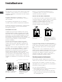
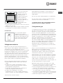
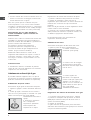
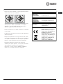
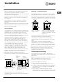
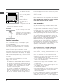
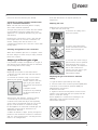
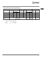
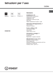
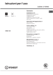
Istruzioni per luso CUCINA Sommario IT Italiano, 1 GB English,14 Installazione, 2-6 Posizionamento e livellamento Collegamento elettrico Collegamento gas Adattamento a diversi tipi di gas Dati tecnici Tabella caratteristiche bruciatori e ugelli Descrizione dellapparecchio, 7 Vista dinsieme Pannello di controllo Avvio e utilizzo, 8-10 Uso del piano cottura Uso del forno Tabella cottura in forno KP6T21S/IT KP6T21S/I Precauzioni e consigli, 11 Sicurezza generale Smaltimento Risparmiare e rispettare lambiente Manutenzione e cura, 12 Escludere la corrente elettrica Pulire lapparecchio Manutenzione rubinetti gas Sostituire la lampadina di illuminazione del forno Assistenza, 13 Assistenza attiva 7 giorni su 7 IT Installazione IT È importante conservare questo libretto per poterlo consultare in ogni momento. In caso di vendita, di cessione o di trasloco, assicurarsi che resti insieme allapparecchio. Leggere attentamente le istruzioni: ci sono importanti informazioni sullinstallazione, sulluso e sulla sicurezza. Linstallazione dellapparecchio va effettuata secondo queste istruzioni da personale qualificato. Qualsiasi intervento di regolazione o manutenzione deve essere eseguito con la cucina disinserita dallimpianto elettrico. Dopo un uso prolungato dellapparecchio, è consigliabile aprire una finestra o aumentare la velocità di eventuali ventilatori. Scarico dei fumi della combustione Lo scarico dei fumi della combustione deve essere assicurato tramite una cappa collegata a un camino a tiraggio naturale di sicura efficienza, oppure mediante un elettroventilatore che entri automaticamente in funzione ogni volta che si accende lapparecchio (vedi figure). Ventilazione dei locali Lapparecchio può essere installato solo in locali permanentemente ventilati, secondo le norme UNICIG 7129 e 7131 e successivi aggiornamenti in vigore. Nel locale in cui viene installato lapparecchio deve poter affluire tanta aria quanta ne viene richiesta dalla regolare combustione del gas (la portata di aria non deve essere inferiore a 2 m3/h per kW di potenza installata). Le prese di immisione aria, protette da griglie, devono avere un condotto di almeno 100 cm2 di sezione utile ed essere collocate in modo da non poter essere ostruite, neppure parzialmente (vedi figura A). Tali prese devono essere maggiorate nella misura del 100% con un minimo di 200 cm2 qualora il piano di lavoro dellapparecchio sia privo del dispositivo di sicurezza per assenza di fiamma e quando lafflusso dellaria avviene in maniera indiretta da locali adiacenti (vedi figura B) purché non siano parti comuni dellimmobile, ambienti con pericolo di incendio o camere da letto dotati di un condotto di ventilazione con lesterno come descritto sopra. Locale adiacente Locale da ventilare A B Scarico direttamente allesterno Scarico tramite camino o canna fumaria ramificata (riservata agli apparecchi di cottura) I gas di petrolio liquefatti, più pesanti dellaria, ristagnano in basso, perciò i locali contenenti bidoni di GPL devono prevedere aperture verso lesterno per levacuazione dal basso di eventuali fughe di gas. I bidoni di GPL, vuoti o parzialmente pieni, non devono essere installati o depositati in locali o vani a livello più basso del suolo (cantinati, ecc.). Tenere nel locale solo il bidone in utilizzo, lontano da sorgenti di calore (forni, camini, stufe) capaci di portarlo a temperature superiori ai 50°C. Posizionamento e livellamento È possibile installare lapparecchio di fianco a mobili che non superino in altezza il piano di lavoro. Assicurarsi che la parete a contatto con il retro dellapparecchio sia di materiale non infiammabile e resistente al calore (T 90°C). A Apertura di ventilazione per laria comburente 2 Maggiorazione della fessura fra porta e pavimento Per una corretta installazione: porre lapparecchio in cucina, in sala da pranzo o in un monolocale (non in bagno); se il piano della cucina è più alto di quello dei mobili, essi devono essere posti ad almeno 600 mm dallapparecchio; se la cucina viene installata sotto un pensile, esso dovrà Min. 600 mm. mantenere una distanza minima dal piano di 420 mm. Tale distanza deve essere di 700 mm se i pensili sono infiammabili (vedi figura); non posizionare tende dietro la cucina o a meno di 200 mm dai suoi lati; eventuali cappe devono essere installate secondo le indicazioni del relativo libretto di istruzione. 420 mm. Min. min. 650 mm. with hood min. 700 mm. without hood 420 mm. Min. HOOD Livellamento Se è necessario livellare lapparecchio, avvitare i piedini di regolazione forniti in dotazione nelle apposite sedi poste negli angoli alla base della cucina (vedi figura). Collegamento elettrico Montare sul cavo una spina normalizzata per il carico indicato nella targhetta caratteristiche posta sullapparecchio (vedi tabella Dati tecnici). In caso di collegamento diretto alla rete è necessario interporre tra lapparecchio e la rete un interruttore onnipolare con apertura minima fra i contatti di 3 mm, dimensionato al carico e rispondente alle norme nazionali in vigore (il filo di terra non deve essere interrotto dallinterruttore). Il cavo di alimentazione deve essere posizionato in modo tale che in nessun punto superi di 50°C la temperatura ambiente. Prima di effettuare lallacciamento accertarsi che: la presa abbia la messa a terra e sia a norma di legge; la presa sia in grado di sopportare il carico massimo di potenza della macchina, indicato della targhetta caratteristiche; la tensione di alimentazione sia compresa nei valori nella targhetta caratteristiche; la presa sia compatibile con la spina dellapparecchio. In caso contrario sostituire la presa o la spina; non usare prolunghe e multiple. Ad apparecchio installato, il cavo elettrico e la presa della corrente devono essere facilmente raggiungibili. IT Il cavo non deve subire piegature o compressioni. Il cavo deve essere controllato periodicamente e sostituito solo da tecnici autorizzati. Lazienda declina ogni responsabilità qualora queste norme non vengano rispettate. Collegamento gas Il collegamento alla rete del gas o alla bombola del gas può essere effettuato con un tubo flessibile in gomma o in acciaio, secondo le norme UNI-CIG 7129 e 7131 e successivi aggiornamenti in vigore e dopo essersi accertati che lapparecchio sia regolato per il tipo di gas con cui sarà alimentato (vedi etichetta di taratura sul coperchio: in caso contrario vedi sotto). Nel caso di alimentazione con gas liquido da bombola, utilizzare regolatori di pressione conformi alle norme UNI EN 12864 e successivi aggiornamenti in vigore. Per facilitare lallacciamento, lalimentazione del gas è orientabile lateralmente*: invertire il portagomma per il collegamento con il tappo di chiusura e sostituire la guarnizione di tenuta fornita in dotazione. Per un sicuro funzionamento, per un adeguato uso dellenergia e per una maggiore durata dellapparecchio, assicurarsi che la pressione di alimentazione rispetti i valori indicati nella tabella Caratteristiche bruciatori e ugelli (vedi sotto). Allacciamento gas con tubo flessibile in gomma Verificare che il tubo risponda alle norme UNI-CIG 7140 in vigore. Il diametro interno del tubo deve essere: 8 mm per alimentazione con gas liquido; 13 mm per alimentazione con gas metano. Effettuato lallacciamento assicurarsi che il tubo: non sia in nessun punto a contatto con parti che raggiungono temperature superiori a 50°C; non sia soggetto ad alcuno sforzo di trazione e di torsione e non presenti pieghe o strozzature; non venga a contatto con corpi taglienti, spigoli vivi, parti mobili e non sia schiacciato; sia facilmente ispezionabile lungo tutto il percorso per poter controllare il suo stato di conservazione; abbia una lunghezza inferiore a 1500 mm; *Presente solo su alcuni modelli. 3 IT sia ben calzato alle sue due estremità, dove va fissato con fascette di serraggio conformi alle norme UNI-CIG 7141 in vigore. Se una o più di queste condizioni non può essere rispettata o se la cucina viene installata secondo le condizioni della classe 2 - sottoclasse 1 (apparecchio incassato tra due mobili), bisogna ricorrere al tubo flessibile in acciaio (vedi sotto). Allacciamento gas con tubo flessibile in acciaio inossidabile a parete continua con attacchi filettati Verificare che il tubo sia conforme alle norme UNICIG 9891 e le guarnizioni di tenuta metalliche in alluminio conformi alla UNI 9001-2 o guarnizioni in gomma conformi alla UNI EN 549. Per mettere in opera il tubo eliminare il portagomma presente sullapparecchio (il raccordo di entrata del gas allapparecchio è filettato 1/2 gas maschio cilindrico). Regolazione del minimo dei bruciatori del piano: 1. portare il rubinetto sulla posizione di minimo; 2. togliere la manopola e agire sulla vite di regolazione posta allinterno o di fianco allastina del rubinetto fino a ottenere una piccola fiamma regolare. Nel caso di gas naturale, la vite di regolazione dovrà essere svitata in senso antiorario; 3. verificare che, ruotando rapidamente il rubinetto dalla posizione di massimo a quella di minimo, non si abbiano spegnimenti del bruciatore. I bruciatori del piano non necessitano di regolazione dellaria primaria. Adattamento del forno Sostituzione dellugello del bruciatore del forno: 1. aprire la porta del forno completamente; 2. estrarre il fondo forno scorrevole (vedi figura); Effettuare lallacciamento in modo che la lunghezza della tubatura non superi i 2 metri di estensione massima, e assicurarsi che il tubo non venga a contatto con parti mobili e non sia schiacciato. 3. svitare la vite di fissaggio del bruciatore e rimuovere il bruciatore del forno dopo aver tolto la vite V; Controllo tenuta A installazione ultimata, controllare la perfetta tenuta di tutti i raccordi utilizzando una soluzione saponosa e mai una fiamma. V Adattamento a diversi tipi di gas È possibile adattare lapparecchio a un tipo di gas diverso da quello per il quale è predisposto (indicato sulletichetta di taratura sul coperchio). Adattamento del piano cottura Sostituzione degli ugelli dei bruciatori del piano: 1. togliere le griglie e sfilare i bruciatori dalle loro sedi; 2. svitare gli ugelli, servendosi di una chiave a tubo da 7 mm (vedi figura), e sostituirli con quelli adatti al nuovo tipo di gas (vedi tabella Caratteristiche bruciatori e ugelli); 3. rimettere in posizione tutti i componenti seguendo le operazioni inverse rispetto alla sequenza di cui sopra. 4 ugelli). 4. svitare lugello del bruciatore con lapposita chiave a tubo per ugelli (vedi figura) o con una chiave a tubo di 7 mm e sostituirlo con quello adatto al nuovo tipo di gas (vedi tabella Caratteristiche bruciatori e Regolazione del minimo del bruciatore forno gas: 1. accendere il bruciatore (vedi Avvio e Utilizzo); 2. portare la manopola sulla posizione di minimo (MIN) dopo averla lasciato per 10 minuti circa in quella di massimo (MAX); 3. togliere la manopola; 4. agire sulla vite di regolazione posta allesterno dellastina del termostato (vedi figure) fino a ottenere una piccola fiamma regolare. Nel caso di gas naturale, la vite di regolazione dovrà essere svitata in senso antiorario. 5. verificare che ruotando rapidamente la manopola dalla posizione MAX a quella MIN o con rapide aperture e chiusure della porta del forno non si abbiano spegnimenti del bruciatore. Fare attenzione ai cavi delle candele e ai tubi delle termocoppie. Il bruciatore del forno non necessita di regolazione dellaria primaria. Dopo la regolazione con un gas diverso da quello di collaudo, sostituire la vecchia etichetta di taratura con quella corrispondente al nuovo gas, reperibile presso i Centri Assistenza Tecnica Autorizzata. DATI TECNICI IT Dimensioni Forno HxLxP 31x43,5x43,5 cm Volume lt. 58 Tensione e frequenza di alimentazione vedi targhetta caratteristiche Bruciatori adattabili a tutti i tipi di gas indicati nella targhetta caratteristiche. Direttive Comunitarie: 2006/95/CEE del 12/12/06 (Bassa Tensione) e successive modificazioni - 89/336/CEE del 03/05/89 (Compatibilità Elettromagnetica) e successive modificazioni - 90/369/CEE del 29/06/90 (Gas) e successive modificazioni -93/68/CEE del 22/07/93 e successive modificazioni - 2002/96/EC. Qualora la pressione del gas sia diversa (o variabile) da quella prevista, è necessario installare sulla tubazione dingresso un regolatore di pressione, secondo le norme EN 88-1 e EN88-2 in vigore per i regolatori per gas canalizzati. 5 IT Tabella caratteristiche bruciatori e ugelli Tabella 1 Gas liquido Diametro Potenza termica By-pass (mm) kW (H.s.*) 1/100 Ugello 1/100 Gas naturale Portata * g/h Ugello 1/100 Portata * l/h BRUCIATORE Nomin. Ridot. (mm) (mm) G30 G31 (mm) G20 C. Rapido 100 3.00 0.7 40 86 218 214 116 286 B. Semirapido 75 1.65 0.4 30 64 120 118 96 157 A. Ausiliario 55 1.0 0.3 27 50 73 71 71 95 D. Tripla Corona 130 3.25 1.3 57 91 236 232 124 309 2.6 0.7 49 78 189 186 113 248 28-30 20 35 37 25 45 Forno Gas Pressioni di alimentazione * ** *** 6 A 15°C e 1013 mbar-gas secco Propano P.C.S. = 50.37 MJ/Kg Butano P.C.S. = 49.47 MJ/Kg Naturale P.C.S. = 37.78 MJ/m3 Nominale (mbar) Minima (mbar) Massima (mbar) 20 17 25 Descrizione dellapparecchio Vista dinsieme IT Griglia del piano di lavoro Bruciatore a gas semirapido Bruciatore a gas tripla corona Bruciatore a gas rapido Pannello di controllo Bruciatore a gas ausiliario Pannello di controllo Spia funzionamento grill elettrico Manopola brucitori gas Manopola forno gas e grill elettrico Pulsante luce forno Manopola contaminuti 7 Avvio e utilizzo IT Uso del piano cottura Bruciatore Accensione dei bruciatori In corrispondenza di ogni manopola BRUCIATORE è indicato con un cerchietto pieno il bruciatore associato. Per accendere un bruciatore del piano cottura: 1. avvicinare al bruciatore una fiamma o un accendigas; 2. premere e contemporaneamente ruotare in senso antiorario la manopola BRUCIATORE sul simbolo di fiamma massima . 3. regolare la potenza della fiamma desiderata, ruotando in senso antiorario la manopola BRUCIATORE: sul minimo una posizione intermedia. , sul massimo Rapido (R) 24 - 26 Semi Rapido (S) 16 - 22 Ausiliario (A) 10 - 14 Tripla Corona (TC) 24 - 26 Per identificare il tipo di bruciatore fate riferimento ai disegni presenti nel paragrafo "Caratteristiche dei bruciatori ed ugelli". Evitare che le pentole fuoriescano dai bordi del piano durante luso. o su Lapparecchio è dotato di accensione elettronica integrata allinterno della manopola. Per accendere il bruciatore prescelto è sufficiente ruotare la manopola corrispondente in senso antiorario fino al simbolo della fiamma grande, premerla a fondo per attivare laccensione elettronica e tenerla premuta fino allavvenuta accensione. Può accadere che il bruciatore si spenga al momento del rilascio della manopola. In questo caso, ripetere loperazione tenendo premuta la manopola più a lungo. In caso di estinzione accidentale delle fiamme, spegnere il bruciatore e aspettare almeno 1 minuto prima di ritentare laccensione. Lapparecchio è dotato di dispositivo di sicurezza per assenza di fiamma, tenere premuta la manopola BRUCIATORE circa 2-3 secondi per mantenere accesa la fiamma e per attivare il dispositivo. Per spegnere il bruciatore ruotare la manopola fino allarresto . Consigli pratici per luso dei bruciatori Per un miglior rendimento dei bruciatori e un consumo minimo di gas occorre usare recipienti a fondo piatto, provvisti di coperchio e proporzionati al bruciatore: 8 ø Diametro Recipienti (cm) Sui modelli dotati di griglietta di riduzione, questultima dovrà essere utilizzata solo per il bruciatore ausiliario, quando si utilizzano dei recipienti di diametro inferiore a 12 cm. Uso del forno Alla prima accensione fare funzionare il forno a vuoto per almeno unora con il termostato al massimo e a porta chiusa. Poi spegnere, aprire la porta del forno e aerare il locale. Lodore che si avverte è dovuto allevaporazione delle sostanze usate per proteggere il forno. Non appoggiare mai oggetti sul fondo del forno perché si rischiano danni allo smalto. La manopola del forno É il dispositivo che permette di selezionare le diverse funzioni del forno e di scegliere la temperatura di cottura più idonea ai cibi da cuocere fra quelle indicate sulla manopola stessa (comprese fra 150°C e 275°C). Il dispositivo di accensione elettronica del forno è integrato allinterno della manopola di comando. Per accendere il bruciatore forno premere a fondo e ruotare la manopola forno in senso antiorario fino alla posizione 8. Dato che il forno è dotato di dispositivo di sicurezza, dopo laccensione del bruciatore è necessario mantenere premuta la manopola forno per circa 6 secondi, in modo da consentire il passaggio del gas finchè non si scalda la termocoppia di sicurezza. Il dispositivo di accensione elettronica del bruciatore forno non deve essere azionato per più di 15 secondi. Se dopo 15 secondi il bruciatore non si è acceso, cessare di agire sulla manopola forno, aprire la porta del forno ed attendere almeno un minuto prima di un nuovo tentativo di accensione del bruciatore. La selezione della temperatura di cottura si ottiene facendo corrispondere lindicazione del valore desiderato con il riferimento posto sul cruscotto; la gamma completa delle temperature ottenibili è riportata qui sotto. La temperatura impostata viene automaticamente raggiunta e mantenuta costante dallorgano di controllo (il termostato) comandato dalla manopola. Posizione 1 (minimo) Posizione 2 Posizione 3 Posizione 4 150° - 155°C Posizione 5 215°C 155°C 175°C 195°C Posizione 6 Posizione 7 Posizione 8 235°C 260°C 275°C Accensione manuale del forno Nel caso di mancanza momentanea di energia elettrica si può accendere il bruciatore del forno manualmente: a ) aprire la porta del forno b ) avvicinare un fiammifero o un accenditore allasola, premere a fondo e ruotare la manopola forno in senso antiorario fino alla posizione 8. c ) ad accensione avvenuta chiudere la porta del forno. nel caso di una estinzione accidentale delle fiamme del bruciatore, chiudere la manopola forno, aprire la porta del forno ed attendere almeno un minuto prima di un nuovo tentativo di accensione del bruciatore. La manopola del grill Il vostro forno è dotato di un grill elettrico. La temperatura assai elevata e diretta del grill consente la immediata rosolatura superficiale dei cibi che, ostacolando la fuoriuscita dei liquidi, li mantiene più teneri internamente. La cottura al grill è particolarmente consigliata per quei piatti che necessitano di elevata temperatura superficiale: bistecche di vitello e manzo, entrecôte, filetto, hamburger etc... Il grill è controllato da un dispositivo termostatico che ne regola il funzionamento Il girarrosto Per azionare il girarrosto procedere nel modo seguente: a ) posizionare la leccarda al 1° ripiano; b ) inserire lapposito sostegno del girarrosto al 3° ripiano e posizionare lo spiedo inserendolo, attraverso lapposito foro, nel girarrosto posizionato nel retro del forno; c ) azionare il girarrosto selezionando con la manopola forno la posizione G Il funzionamento del grill è segnalato dallaccensione della spia GRILL. Effettuare la cottura al grill con la porta del forno chiusa, per ottenere migliori risultati e un sensibile risparmio di energia (10% circa). Luce del forno La lampadina può essere accesa in qualunque momento premendo il tasto LUCE DEL FORNO. Contaminuti Per azionare il Contaminuti procedere come segue: 1. ruotare in senso orario "la manopola CONTAMINUTI di un giro quasi completo per caricare la suoneria; 2. ruotare in senso antiorario # la manopola CONTAMINUTI impostando il tempo desiderato. Ruotando la manopola forno fino alla posizione G si mette in funzione oltre al grill a raggi infrarossi anche il motorino girarrosto, che rimane attivato fino a che il grill è in funzione. 9 IT IT Tabella cottura in forno Cibo da cucinare Peso (Kg) Posizione cottura ripiani dal basso Temperatura (°C) Tempo di preriscaldamento (minuti) Tempo di cottura (minuti) Pasta Lasagne Cannelloni Tagliatelle 2,5 2,5 2,5 3 3 3 210 210 210 - 75-80 75-80 75-80 Carni Vitello Pollo Tacchino Anatra Coniglio Maiale Agnello 1,7 1,5 3,0 1,8 2,0 2,1 1,8 3 3 3 3 3 3 3 230 220 Max 230 230 230 230 - 85-90 110-115 95-100 120-125 105-110 100-110 90-95 Pesci Sgombri Dentice Trota al cartoccio 1,1 1,5 1,0 3 3 3 210-230 210-230 210-230 - 55-60 60-65 40-45 Pizza e torte Napoletana Biscotti Crostata Torta al cioccolato Torta lievitata 1,0 0,5 1,1 1,0 1,0 3 3 3 3 3 Max 180 180 200 200 15 15 15 15 15 30-35 30-35 30-35 45-50 50-55 Cottura al grill Toast Braciole di maiale Sgombri n° 4 1,5 1,1 4 4 4 10 30 35 NB: i tempi di cottura sono indicativi e possono essere modificati in base ai propri gusti personali. Nelle cotture al grill la leccarda va posta sempre al 1° ripiano a partire dal basso. 10 Precauzioni e consigli Lapparecchio è stato progettato e costruito in conformità alle norme internazionali di sicurezza. Queste avvertenze sono fornite per ragioni di sicurezza e devono essere lette attentamente. Sicurezza generale Lapparecchio è stato concepito per un uso di tipo non professionale allinterno dellabitazione. Lapparecchio non va installato allaperto, nemmeno se lo spazio è riparato, perché è molto pericoloso lasciarlo esposto a pioggia e temporali. Non toccare la macchina a piedi nudi o con le mani o con i piedi bagnati o umidi. Non appoggiare oggetti pesanti sulla porta del forno aperta. IT Se la cucina viene posta su di un piedistallo, prendere adeguati accorgimenti affinchè l'apparecchio non scivoli dal piedistallo stesso. Non è previsto che l'apparecchio venga utilizzato da persone (bambini compresi) con ridotte capacità fisiche, sensoriali o mentali, da persone inesperte o che non abbiano familiarità con il prodotto, a meno che non vengano sorvegliate da una persona responsabile della loro sicurezza o non abbiano ricevuto istruzioni preliminari sull'uso dell'apparecchio. Evitare che i bambini giochino con l'apparecchio. Lapparecchio deve essere usato per cuocere alimenti, solo da persone adulte e secondo le istruzioni riportate in questo libretto, valide per i Paesi di destinazione i cui simboli figurano allinizio del libretto. Smaltimento Il libretto riguarda un apparecchio di classe 1 (isolato) o classe 2 sottoclasse 1 (incassato tra due mobili). La direttiva Europea 2002/96/CE sui rifiuti di apparecchiature elettriche ed elettroniche (RAEE), prevede che gli elettrodomestici non debbano essere smaltiti nel normale flusso dei rifiuti solidi urbani. Gli apparecchi dismessi devono essere raccolti separatamente per ottimizzare il tasso di recupero e riciclaggio dei materiali che li compongono e impedire potenziali danni per la salute e lambiente. Il simbolo del cestino barrato è riportato su tutti i prodotti per ricordare gli obblighi di raccolta separata. Si potranno consegnare gli elettrodomestici dismessi al servizio di raccolta pubblico, portarli presso le apposite aree comunali o, se previsto dalla legge nazionale in materia, renderli ai rivenditori contestualmente allacquisto di nuovi prodotti di tipo equivalente. Tutti i principali produttori di elettrodomestici sono attivi nella creazione e gestione di sistemi di raccolta e smaltimento degli apparecchi dismessi. Tenere lontani i bambini. Evitare che il cavo di alimentazione di altri elettrodomestici entri in contatto con parti calde dellapparecchio. Non ostruire le aperture di ventilazione e di smaltimento di calore. Utilizzare sempre guanti da forno per inserire o estrarre recipienti. Non utilizzare liquidi infiammabili (alcol, benzina, ecc.) in prossimità dellapparecchio quando esso è in uso. Non riporre materiale infiammabile nel vano inferiore di deposito o nel forno: se lapparecchio viene messo inavvertitamente in funzione potrebbe incendiarsi. Smaltimento del materiale di imballaggio: attenersi alle norme locali, così gli imballaggi potranno essere riutilizzati. Risparmiare e rispettare lambiente Quando lapparecchio non è utilizzato, assicurarsi sempre che le manopole siano nella posizione e che rubinetto del gas sia chiuso. Si raccomanda di effettuare sempre le cotture al GRILL a porta chiusa: sia per ottenere migliori risultati che per un sensibile risparmio di energia (10% circa). Non staccare la spina dalla presa della corrente tirando il cavo, bensì afferrando la spina. Mantenere efficienti e pulite le guarnizioni, in modo che aderiscano bene alla porta e non procurino dispersioni di calore. Non fare pulizia o manutenzione senza aver prima staccato la spina dalla rete elettrica. In caso di guasto, in nessun caso accedere ai meccanismi interni per tentare una riparazione. Contattare lAssistenza. 11 Manutenzione e cura IT Escludere la corrente elettrica Controllare le guarnizioni del forno Prima di ogni operazione isolare lapparecchio dalla rete di alimentazione elettrica. Pulire lapparecchio Controllare periodicamente lo stato della guarnizione attorno alla porta del forno. In caso risulti danneggiata rivolgersi al Centro Assistenza Autorizzato più vicino. È consigliabile non usare il forno fino allavvenuta riparazione. Non utilizzare mai pulitori a vapore o ad alta pressione per la pulizia dellapparecchio. Manutenzione rubinetti gas Le parti esterne smaltate o inox e le guarnizioni in gomma possono essere pulite con una spugnetta imbevuta di acqua tiepida e sapone neutro. Se le macchie sono difficili da asportare usare prodotti specifici. Sciacquare abbondantemente e asciugare dopo la pulizia. Non usare polveri abrasive o sostanze corrosive. Le griglie, i cappellotti, le corone spartifiamma e i bruciatori del piano cottura sono estraibili per facilitare la pulizia; lavarli in acqua calda e detersivo non abrasivo, avendo cura di togliere ogni incrostazione e attendere che siano perfettamente asciutti. Pulire frequentemente la parte terminale dei dispositivi di sicurezza per assenza di fiamma. Linterno del forno va pulito preferibilmente ogni volta dopo luso, quando è ancora tiepido. Usare acqua calda e detersivo, risciaquare e asciugare con un panno morbido. Evitare gli abrasivi. Pulire il vetro della porta con spugne e prodotti non abrasivi e asciugare con un panno morbido; non usare materiali ruvidi abrasivi o raschietti metallici affilati che possono graffiare la superficie e causare la frantumazione del vetro. Gli accessori possono essere lavati come normali stoviglie, anche in lavastoviglie. Evitare di chiudere il coperchio quando i bruciatori sono accesi o sono ancora caldi. 12 Con il tempo può verificarsi il caso di un rubinetto che si blocchi o presenti difficoltà nella rotazione, pertanto sarà necessario provvedere alla sostituzione del rubinetto stesso. Questa operazione deve essere effettuata da un tecnico autorizzato dal costruttore. Sostituire la lampadina di illuminazione del forno 1. Dopo aver disinserito il forno dalla rete elettrica, togliere il coperchio in vetro del portalampada (vedi figura). 2. Svitare la lampadina e sostituirla con una analoga: tensione 230V, potenza 25 W, attacco E 14. 3. Rimontare il coperchio e ricollegare il forno alla rete elettrica. Assistenza Non ricorrere mai a tecnici non autorizzati. IT Comunicare: Il tipo di anomalia; Il modello della macchina (Mod.) Il numero di serie (S/N) Queste ultime informazioni si trovano sulla targhetta caratteristiche posta sullapparecchio Assistenza attiva 7 giorni su 7 In caso di necessità dintervento chiamare il Numero Unico Nazionale 199.199.199*. Un operatore sarà a completa disposizione per fissare un appuntamento con il Centro Assistenza Tecnico Autorizzato più vicino al luogo da cui si chiama. È attivo 7 giorni su 7, sabato e domenica compresi, e non lascia mai inascoltata una richiesta. *Al costo di 14,26 centesimi di Euro al minuto(iva inclusa) dal Lun. al Ven. dalle 08:00 alle 18:30, il Sab. dalle 08:00 alle 13:00 e di 5,58 centesimi di Euro al minuto (iva inclusa) dal Lun. al Ven. dalle 18:30 alle 08:00, il Sab. dalle 13:00 alle 08:00 e i giorni festivi, per chi chiama da telefono fisso. Per chi chiama da radiomobile le tariffe sono legate al piano tariffario delloperatore telefonico utilizzato. Le suddette tariffe potrebbero essere soggette a variazione da parte delloperatore telefonico; per maggiori informazioni consultare il sito www.indesit.com. 13 Operating Instructions COOKER Contents GB IT Italiano, 1 GB English, 14 Installation, 15-19 Positioning and levelling Electrical connection Gas connection Adapting to different types of gas Technical data Table of burner and nozzle specifications Description of the appliance, 20 Overall view Control panel Start-up and use, 21-23 Using the hob Using the oven Oven cooking advice table KP6T21S/IT KP6T21S/I Precautions and tips, 24 General safety Disposal Respecting and conserving the environment Care and maintenance, 25 Switching the appliance off Cleaning the appliance Gas tap maintenance Replacing the oven light bulb Assistance, 26 Installation Before operating your new appliance please read this instruction booklet carefully. It contains important information concerning the safe installation and operation of the appliance. Please keep these operating instructions for future reference. Pass them on to possible new owners of the appliance. Disposing of combustion fumes GB The efficient disposal of combustion fumes should be guaranteed using a hood which is connected to a safe and efficient natural suction chimney, or using an electric fan which begins to operate automatically every time the appliance is switched on (see figure). The appliance must be installed by a qualified professional in accordance with the instructions provided. Any necessary adjustment or maintenance must be performed after the cooker has been disconnected from the electricity supply. Room ventilation The appliance may only be installed in permanently ventilated rooms, in accordance with current national legislation and any subsequent amendments in force. The room in which the appliance is installed must be ventilated adequately in order to provide as much air as is needed by the normal gas combustion process (the flow of air must not be lower than 2 m3/h per kW of installed power). The air inlets, protected by grilles, should have a duct with an inner cross section of at least 100 cm2 and should be positioned so that they are not liable to even partial obstruction (see figure A). These inlets should be enlarged by 100% - with a minimum of 200 cm2 - whenever the surface of the hob is not equipped with a flame failure safety device. When the flow of air is provided in an indirect manner from adjacent rooms (see figure B), provided that these are not communal parts of a building, areas with increased fire hazards or bedrooms, the inlets should be fitted with a ventilation duct leading outside as described above. A B Adjacent room Room requiring ventilation A Ventilation opening for comburent air Increase in the gap between the door and the flooring After prolonged use of the appliance, it is advisable to open a window or increase the speed of any fans used. Fumes channelled straight outside Fumes channelled through a chimney or a branched flue system (reserved for cooking appliances) The liquefied petroleum gases are heavier than air and collect by the floor, therefore all rooms containing LPG cylinders must have openings leading outside so that any leaked gas can escape easily. LPG cylinders, therefore, whether partially or completely full, must not be installed or stored in rooms or storage areas which are below ground level (cellars, etc.). Only the cylinder being used should be stored in the room; this should also be kept well away from sources of heat (ovens, chimneys, stoves) which may cause the temperature of the cylinder to rise above 50°C. Positioning and levelling The appliance may be installed alongside any cupboards whose height does not exceed that of the hob surface. Make sure that the wall which is in contact with the back of the appliance is made from a nonflammable, heat-resistant material (T 90°C). To install the appliance correctly: Place it in the kitchen, the dining room or the studio flat (not in the bathroom). If the top of the hob is higher than the cupboards, the appliance must be installed at least 600 mm away from them. If the cooker is installed underneath a wall cabinet, there must be a minimum distance of 420 mm between this cabinet and the top of the hob. 15 This distance should be increased to 700 mm if the wall cabinets Min. 600 mm. are flammable (see figure). Do not position blinds behind the cooker or less than 200 mm away from its sides. Any hoods must be installed in accordance with the instructions listed in the relevant operating manual. GB 420 mm. Min. min. 650 mm. with hood min. 700 mm. without hood 420 mm. Min. HOOD Levelling If it is necessary to level the appliance, screw the adjustable feet into the places provided on each corner of the base of the cooker (see figure). Electrical connection Install a standardised plug corresponding to the load indicated on the appliance data plate (see Technical data table). The appliance must be directly connected to the mains using an omnipolar switch with a minimum contact opening of 3 mm installed between the appliance and the mains. The switch must be suitable for the charge indicated and must comply with current electrical regulations (the earthing wire must not be interrupted by the switch). The supply cable must be positioned so that it does not come into contact with temperatures higher than 50°C at any point. Before connecting the appliance to the power supply, make sure that: The appliance is earthed and the plug is compliant with the law. The socket can withstand the maximum power of the appliance, which is indicated by the data plate. The voltage is in the range between the values indicated on the data plate. The socket is compatible with the plug of the appliance. If the socket is incompatible with the plug, ask an authorised technician to replace it. Do not use extension cords or multiple sockets. * Only available in certain models 16 Once the appliance has been installed, the power supply cable and the electrical socket must be easily accessible. The cable must not be bent or compressed. The cable must be checked regularly and replaced by authorised technicians only. The manufacturer declines any liability should these safety measures not be observed. Gas connection Connection to the gas network or to the gas cylinder may be carried out using a flexible rubber or steel hose, in accordance with current national legislation and after making sure that the appliance is suited to the type of gas with which it will be supplied (see the rating sticker on the cover: if this is not the case see below). When using liquid gas from a cylinder, install a pressure regulator which complies with current national regulations. To make connection easier, the gas supply may be turned sideways*: reverse the position of the hose holder with that of the cap and replace the gasket supplied with the appliance. Make sure that the gas supply pressure is consistent with the values indicated in the Table of burner and nozzle specifications (see below). This will ensure the safe operation and durability of your appliance while maintaining efficient energy consumption. Gas connection using a flexible rubber hose Make sure that the hose complies with ccurrent national legislation. The internal diameter of the hose must measure: 8 mm for a liquid gas supply; 13 mm for a methane gas supply. Once the connection has been performed, make sure that the hose: Does not come into contact with any parts which reach temperatures of over 50°C. Is not subject to any pulling or twisting forces and that it is not kinked or bent. Does not come into contact with blades, sharp corners or moving parts and that it is not compressed. Is easy to inspect along its whole length so that its condition may be checked. Is shorter than 1500 mm. Fits firmly into place at both ends, where it will be fixed using clamps which comply with current national legislation. If one or more of these conditions is not fulfilled or if the cooker must be installed according to the conditions listed for class 2 - subclass 1 appliances (installed between two cupboards), the flexible steel hose must be used instead (see below). Connecting a flexible jointless stainless steel pipe to a threaded attachment Make sure that the hose and gaskets comply with current national legislation. To begin using the hose, remove the hose holder on the appliance (the gas supply inlet on the appliance is a cylindrical threaded 1/2 gas male attachment). The hob burners do not require primary air adjustment. Adapting the oven Replacing the oven burner nozzle: 1. Open the oven door fully. 2. Remove the sliding oven base (see figure). Perform the connection in such a way that the hose length does not exceed a maximum of 2 metres, making sure that the hose is not compressed and does not come into contact with moving parts. 3. Loosen the burner fixing screws and take out the oven burner after removing the screw V. Checking the tightness of the connection When the installation process is complete, check the hose fittings for leaks using a soapy solution. Never use a flame. Adapting to different types of gas It is possible to adapt the appliance to a type of gas other than the default type (this is indicated on the rating label on the cover). Adapting the hob Replacing the nozzles for the hob burners: 1. Remove the hob grids and slide the burners off their seats. 2. Unscrew the nozzles using a 7 mm socket spanner (see figure), and replace them with nozzles suited to the new type of gas (see Burner and nozzle specifications table). 3. Replace all the components by following the above instructions in reverse. Adjusting the hob burners minimum setting: 1. Turn the tap to the minimum position. 2. Remove the knob and adjust the regulatory screw, which is positioned inside or next to the tap pin, until the flame is small but steady. If the appliance is connected to natural gas, the adjustment screw must be loosened in an anticlockwise direction. 3. While the burner is alight, quickly change the position of the knob from minimum to maximum and vice versa several times, checking that the flame is not extinguished. GB V 4. Unscrew the nozzle using a special nozzle socket spanner (see figure) or with a 7 mm socket spanner, and replace it with a new nozzle that is suited to the new type of gas (see Burner and nozzle specifications table). Adjusting the gas oven burners minimum setting: 1. Light the burner (see Start-up and Use). 2. Turn the knob to the minimum position (MIN) after it has been in the maximum position (MAX) for approximately 10 minutes. 3. Remove the knob. 4. Tighten or loosen the adjustment screws on the outside of the thermostat pin (see figure) until the flame is small but steady. If the appliance is connected to natural gas, the adjustment screw must be loosened in an anticlockwise direction. 17 GB 5. Turn the knob from the MAX position to the MIN position quickly or open and shut the oven door, making sure that the burner is not extinguished. Be careful of the spark plug wires and the thermocouple tubes. The oven burner does not require primary air adjustment. After adjusting the appliance so it may be used with a different type of gas, replace the old rating label with a new one which corresponds to the new type of gas (these labels are available from Authorised Technical Assistance Centres). Should the gas pressure used be different (or vary slightly) from the recommended pressure, a suitable pressure regulator must be fitted to the inlet hose in accordance with current national regulations relating to regulators for channelled gas. 18 TECHNICAL DATA Oven dimensions (HxWxD) Volume Power supply voltage and frequency Burners 31x43.5x43.5 cm 58 l see data plate may be adapted for use with any type of gas shown on the data plate EC Directives: 2006/95/EEC dated 12.12.06 (Low Voltage) and subsequent amendments - 89/336/EEC dated 03/05/89 (Electromagnetic Compatibility) and subsequent amendments 90/369/EEC dated 29/06/90 (Gas) and subsequent amendments - 93/68/EEC dated 22/07/93 and subsequent amendments 2002/96/EC. Table of burner and nozzle specifications Table 1 Burner C. Rapid B. Semi-rapid A. Auxiliary D. Triple ring Gas oven Supply pressure * ** *** At 15°C and Propane Butane Natural Diameter (mm) 100 75 55 130 Heating power By-pass kW (H.s.*) 1/100 mm) Nomin. Red. 3.00 0.7 40 1.65 0.4 30 1.0 0.3 27 3.25 1.3 57 2.6 0.7 49 Nominal (mbar) Minimal (mbar) Maximised (mbar) GB Liquid gas Nozzle Flow rate * g/h 1/100 mm) G30 G31 86 218 214 64 120 118 50 73 71 91 236 232 78 186 186 28-30 37 20 25 35 45 Natural gas Nozzle Flow rate * 1/100 l/h (mm) G20 116 96 71 124 113 286 157 95 309 248 20 17 25 1013 mbar - dry gas P.C.S. = 50.37 MJ/kg P.C.S. = 49.47 MJ/kg P.C.S. = 37.78 MJ/m3 19 Description of the appliance GB Overall view Hob grid Semi-rapid gas burner Triple ring gas burner Rapid gas burner Control panel Auxliary gas burner Control panel 20 Start-up and use Using the hob Lighting the burners For each BURNER knob there is a complete ring showing the strength of the flame for the relevant burner. To light one of the burners on the hob: 1. Bring a flame or gas lighter close to the burner. 2. Press the BURNER knob and turn it in an anticlockwise direction so that it is pointing to the maximum flame setting . 3. Adjust the intensity of the flame to the desired level by turning the BURNER knob in an anticlockwise direction. This may be the minimum setting , the maximum setting , or any position in between the two. The appliance is fitted with an electronic lighting device which is integrated into the knob. Simply light the desired burner by turning the corresponding knob in an anti-clockwise direction, until it is aligned with the large flame symbol, press it all the way in to activate the electronic ignition and hold it in that position until the burner is lit. The burner might be extinguished when the knob is released. If this occurs, repeat the process, holding the knob down for a longer period of time. If the flame is accidentally extinguished, switch off the burner and wait for at least 1 minute before attempting to relight it. The appliance is equipped with a flame failure safety device; press and hold the BURNER knob for approximately 2-3 seconds to keep the flame alight and to activate the device. To switch the burner off, turn the knob until it reaches the stop position . Practical advice on using the burners For the burners to work in the most efficient way possible and in order to save on the amount of gas consumed, it is recommended that only pans which have a lid and a flat base are used. They should also be suited to the size of the burner. To identify the type of burner, please refer to the diagrams contained in the Burner and nozzle specifications. Burner Rapid (R) Semi-rapid (S) Auxiliary (A) Triple.ring (TC) ø Cookware Diameter (cm) 24 - 26 16 - 22 10 - 14 24 - 26 GB Make sure the pans do not overlap the edges of the hob while it is being used. For models equipped with a reducer grid, the latter must be used only for the auxiliary burner, when pans with a diameter of less than 12 cm are used. Using the oven The first time you use your appliance, heat the empty oven with its door closed at its maximum temperature for at least half an hour. Ensure that the room is well ventilated before switching the oven off and opening the oven door. The appliance may emit a slightly unpleasant odour caused by protective substances used during the manufacturing process burning away. Never put objects directly on the bottom of the oven; this will prevent the enamel coating from being damaged. The oven knob This is the device which is used to select the various oven functions and the most suitable cooking temperature for the foods (temperatures between 150°C and 275°C are also indicated on the knob). The electronic oven ignition device is built into the control knob. To light the burner, press the knob in fully and turn it in an anticlockwise direction until it reaches position 8. Given that the oven is fitted with a safety device, after the burner has been lit the oven knob should be held in that position for approximately 6 seconds, in order to allow the gas to pass through until the safety thermocouple heats up. The electronic oven burner ignition device should not be activated for more than 15 seconds. If after 15 seconds the burner has not been ignited, release the oven knob, open the oven door and wait for at least one minute before attempting to ignite the burner again. The cooking temperature is selected by aligning the value indication with the reference mark on the control panel; the complete range of temperatures which are available for selection is displayed below. 21 GB The oven will automatically reach the set temperature, which is kept constant by the corresponding monitoring device (the thermostat) controlled by the knob. Position 1 (minimum) Position 2 Position 3 Position 4 150° - 155°C Position 5 155°C Position 6 175°C Position 7 195°C Position 8 215°C 235°C 260°C 275°C Switching the oven on manually In the event of a momentary lapse in the electricity supply, the oven burner may be ignited manually: a) Open the oven door. b) Bring a match or lighter close to the opening, press the oven knob and turn it in an anticlockwise direction until it reaches position 8. c) When the burner has been lit successfully, close the oven door. If the burner flame is accidentally extinguished, shut off the oven knob, open the oven door and wait for at least one minute before attempting to light the burner again. The grill knob Your oven is fitted with an electric grill. The extremely high and direct temperature of the grill makes it possible to brown the surface of meats and roasts while locking in the juices to keep them tender. The grill is also highly recommended for dishes that require a high surface temperature: such as beef steaks, veal, rib steak, fillets, hamburgers etc... The grill is controlled by a thermostat which adjusts its operation. By turning the oven knob until it reaches the G position, the rotisserie spit motor is activated as well as the infrared grill. This motor will remain active as long as the grill is operating. 22 The rotisserie spit To activate the rotisserie spit, proceed as follows: a) Place the dripping pan on the 1st rack. b) Position the rotisserie support on the 3rd rack and insert the spit towards the rear, threading it through the hole provided. c) Start the rotisserie by turning the oven knob to the G position. The GRILL indicator light shows when the grill is operating. Always use the grill with the oven door shut; this achieves better cooking results and saves energy (approximately 10%). Oven light The light may be switched on at any moment by pressing the OVEN LIGHT button. Timer To activate the Timer proceed as follows: 1. Turn the TIMER knob in a clockwise direction " for almost one complete revolution to set the buzzer. 2. Turn the TIMER knob in an anticlockwise direction # to set the desired length of time. Oven cooking advice table GB Food to be cooked Wt. (wt) Cooking position of shelves from bottom Temperature (°C) Pre-heat time (min.) Cooking time (min.) Paste Lasagne Cannelloni Oven-baked noodles 2,5 2,5 2,5 3 3 3 210 210 210 - 75-80 75-80 75-80 Meat Veal Chicken Turkey Duck Rabbit Pork Lamb 1,7 1,5 3,0 1,8 2,0 2,1 1,8 3 3 3 3 3 3 3 230 220 Max 230 230 230 230 - 85-90 110-115 95-100 120-125 105-110 100-110 90-95 Fish Mackerel Dentex Trout baked in paper 1,1 1,5 1,0 3 3 3 210-230 210-230 210-230 - 55-60 60-65 40-45 Pizze Napolitan 1,0 3 Max 15 30-35 Cake Biscuits Tarts Chocolate cake Yeast cakes 0,5 1,1 1,0 1,0 3 3 3 3 180 180 200 200 15 15 15 15 30-35 30-35 45-50 50-55 Grill cooking Toast Pork chops Mackerel n.4 1,5 1,1 4 4 4 10 30 35 NB: cooking times are approximate and may vary according to personal taste. When cooking using the grill, the dripping pan must always be placed on the 1st oven rack from the bottom. 23 Precautions and tips GB This appliance has been designed and manufactured in compliance with international safety standards. The following warnings are provided for safety reasons and must be read carefully. General safety The appliance was designed for domestic use inside the home and is not intended for commercial or industrial use. The appliance must not be installed outdoors, even in covered areas. It is extremely dangerous to leave the appliance exposed to rain and storms. Do not touch the appliance with bare feet or with wet or damp hands and feet. The appliance must be used by adults only for the preparation of food, in accordance with the instructions provided in this booklet (the instructions apply to all countries listed at the beginning of the booklet). The instruction booklet accompanies a class 1 (insulated) or class 2 - subclass 1 (recessed between 2 cupboards) appliance. Keep children away from the oven. Make sure that the power supply cables of other electrical appliances do not come into contact with the hot parts of the oven. The openings used for the ventilation and dispersion of heat must never be covered. Always use oven gloves when placing cookware in the oven or when removing it. Do not use flammable liquids (alcohol, petrol, etc...) near the appliance while it is in use. Do not place flammable material in the lower storage compartment or in the oven itself. If the appliance is switched on accidentally, the materials could catch fire. Always make sure the knobs are in the position and that the gas tap is closed when the appliance is not in use. When unplugging the appliance, always pull the plug from the mains socket; do not pull on the cable. Never perform any cleaning or maintenance work without having disconnected the appliance from the electricity mains. If the appliance breaks down, under no circumstances should you attempt to perform the repairs yourself. Repairs carried out by 24 inexperienced persons may cause injury or further malfunctioning of the appliance. Contact Assistance. Do not rest heavy objects on the open oven door. If the cooker is placed on a pedestal, take all necessary precautions to ensure that the appliance does not slide off this pedestal. The appliance should not be operated by people (including children) with reduced physical, sensory or mental capacities, by inexperienced individuals or by anyone who is not familiar with the product. These individuals should, at the very least, be supervised by someone who assumes responsibility for their safety or receive preliminary instructions relating to the operation of the appliance. Do not let children play with the appliance. Disposal When disposing of packaging material: observe local legislation so that the packaging may be reused. The European Directive 2002/96/EC relating to Waste Electrical and Electronic Equipment (WEEE) states that household appliances should not be disposed of using the normal solid urban waste cycle. Exhausted appliances should be collected separately in order to optimise the cost of re-using and recycling the materials inside the machine, while preventing potential damage to the atmosphere and to public health. The crossed-out dustbin is marked on all products to remind the owner of their obligations regarding separated waste collection. Exhausted appliances may be collected by the public waste collection service, taken to suitable collection areas in the area or, if permitted by current national legislation, they may be returned to the dealers as part of an exchange deal for a new equivalent product. All major manufacturers of household appliances participate in the creation and organisation of systems for the collection and disposal of old and disused appliances. Respecting and conserving the environment Always keep the oven door closed when using the GRILL mode: this will achieve improved results while saving energy (approximately 10%). Check the door seals regularly and wipe them clean to ensure they are free of debris so that they adhere properly to the door, thus avoiding heat dispersion. Care and maintenance Switching the appliance off Inspecting the oven seals Disconnect your appliance from the electricity supply before carrying out any work on it. Cleaning the appliance Check the door seals around the oven regularly. If the seals are damaged, please contact your nearest Authorised After-sales Service Centre. We recommend that the oven is not used until the seals have been replaced. Never use steam cleaners or pressure cleaners on the appliance. Gas tap maintenance The stainless steel or enamel-coated external parts and the rubber seals may be cleaned using a sponge which has been soaked in lukewarm water and neutral soap. Use specialised products for the removal of stubborn stains. After cleaning, rinse well and dry thoroughly. Do not use abrasive powders or corrosive substances. The hob grids, burner caps, flame spreader rings and burners may be removed to make cleaning easier; wash them in hot water and non-abrasive detergent, making sure all burnt-on residue is removed before drying them thoroughly. Clean the terminal part of the flame failure safety devices* frequently. The inside of the oven should ideally be cleaned after each use, while it is still lukewarm. Use hot water and detergent, then rinse well and dry with a soft cloth. Do not use abrasive products. GB Over time, the tap may become jammed or difficult to turn. If this occurs, the tap must be replaced. This procedure must be performed by a qualified technician who has been authorised by the manufacturer. Replacing the oven light bulb 1. After disconnecting the oven from the electricity mains, remove the glass lid covering the lamp socket (see figure). 2. Unscrew the light bulb and replace it with a similar one: voltage 230 V, wattage 25 W, cap E 14. 3. Replace the lid and reconnect the oven to the electricity supply. Clean the glass part of the oven door using a sponge and a non-abrasive cleaning product, then dry thoroughly with a soft cloth. Do not use rough abrasive material or sharp metal scrapers as these could scratch the surface and cause the glass to crack. The accessories can be washed like everyday crockery, and are even dishwasher safe. Do not close the cover when the burners are alight or when they are still hot. 25 Assistance GB Never use the services of an unauthorised technician. Please have the following information to hand: The type of problem encountered. The appliance model (Mod.). The serial number (S/N). The latter two pieces of information can be found on the data plate located on the appliance. 26 GB 27 05/2008 - 195066196.01 XEROX BUSINESS SERVICES GB 28