1
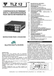
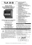
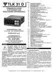
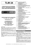
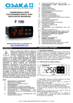
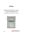
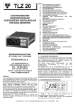
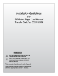
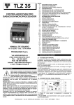
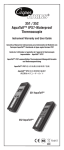
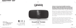
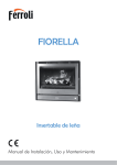
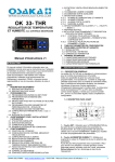
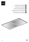
TLY 27- EC
AL
Out
OK +
ISTRUZIONI PER L'USO
OPERATING INSTRUCTIONS
INSTRUCTIONS POUR L'UTILISATION
BEDIENUNGSANLEITUNG
MANUAL DE USUARIO
vr. 01 - 10/04 - cod.: ISTR 06957
TECNOLOGIC S.p.A.
VIA INDIPENDENZA 56 - 27029 VIGEVANO (PV) - ITALY
TEL.: +39 0381 69871 FAX: +39 0381 698730
e-mail: [email protected]
PREMESSA
Nel presente manuale sono contenute le
informazioni necessarie ad una corretta
installazione e le istruzioni per l'utilizzo e la
manutenzione del prodotto, si raccomanda
pertanto di leggerlo attentamente
e di
conservarlo. La presente pubblicazione è di esclusiva
proprietà della TECNOLOGIC S.p.A. la quale pone il divieto
assoluto di riproduzione e divulgazione, anche parziale, se
non espressamente autorizzata. La TECNOLOGIC S.p.A. si
riserva di apportare modifiche estetiche e funzionali in
qualsiasi momento e senza alcun preavviso. Qualora un
guasto o un malfunzionamento dell'apparecchio possa creare
situazioni pericolose o dannose per persone, cose o animali si
ricorda che l'impianto deve essere predisposto con dispositivi
aggiuntivi atti a garantire la sicurezza. La Tecnologic S.p.A. ed
i suoi legali rappresentanti non si ritengono in alcun modo
responsabili per eventuali danni a persone, cose o animali
derivanti da manomissioni, uso improprio, errato o comunque
non conforme alle caratteristiche dello strumento.
FOREWORD
This manual contains the information necessary for the
product to be installed correctly and also instructions for its
maintenance and use; we therefore recommend that the
utmost attention is paid to the following instructions and to
save it. This document is the exclusive property of
TECNOLOGIC S.p.A. which forbids any reproduction and
divulgation , even in part, of the document, unless expressly
authorized. TECNOLOGIC S.p.A. reserves the right to make
any formal or functional changes at any moment and without
any notice. Whenever a failure or a malfunction of the device
may cause dangerous situations for persons, thing or animals,
please remember that the plant has to be equipped with
additional devices which will guarantee safety. Tecnologic
S.p.A. and its legal representatives do not assume any
responsibility for any damage to people, things or animals
deriving from violation, wrong or improper use or in any case
not in compliance with the instrument’s features.
INTRODUCTION
Dans ce manuel sont contenues toutes les informations
nécessaires pour une installation correcte et les instructions
pour l’utilisation et l’entretien du produit, on recommande
donc de lire bien attentivement les instructions suivantes et de
le conserver. Cette publication est de propriété exclusive de la
Société TECNOLOGIC S.p.A. qui interdit absolument la
reproduction et la divulgation, même partielle, si elle n’est pas
expressément autorisée. La Société TECNOLOGIC S.p.A. se
réserve d’apporter des modifications esthétiques et
fonctionnelles à tout moment et sans aucun préavis. Si un
dommage ou un mauvais fonctionnement de l’appareil crée
des situations dangereuses aux personnes, choses ou aux
animaux, nous rappelons que l’installation doit être prévue de
dispositifs électromécaniques supplémentaires en mesure de
garantir la sécurité. La Société Tecnologic S.p.A. et ses
représentants légaux ne se retiennent en aucune façon
responsables pour des dommages éventuels causés à des
personnes ou aux choses et animaux à cause de falsication,
d’utilisation impropre, erronée ou de toute façon non
conforme aux caractéristiques de l’instrument.
VORWORT
In der vorliegenden Anleitung sind alle Angaben enthalten, die
für eine einwandfreie Installation und Verwendung sowie
Wartung des Produktes erforderlich sind. Daher sollten die
nachstehenden Anweisungen aufmerksam gelesen werden.
Alle Rechte der vorliegenden Unterlagen sind vorbehalten.
Nachdruck auch auszugsweise verboten, soweit nicht
ausdrücklich zuvor von TECNOLOGIC S.p.A. genehmigt. Falls
eine
Betriebsstörung
des
Gerätes
Personenoder
Sachschäden verursachen kann, muss die Anlage mit
zusätzlichen
elektromechanischen
Schutzeinrichtungen
abgesichert werden. TECNOLOGIC S.p.A. behält sich das
Recht vor, jederzeit ohne besondere Anzeige jene Änderungen
vorzunehmen, die sie als notwendig erachtet. Die Firma
Tecnologic S.p.A. und ihre gesetzlichen Vertreter weisen jede
Haftung für Personen- oder Sachschäden von sich, die auf
Abänderungen, unsachgemäße, falsche oder nicht den
Merkmalen
des
Gerätes
entsprechende
Verwendung
zurückzuführen sind.
INTRODUCCION
Este manual contiene la información necesaria para instalar
correctamente el equipo y tambien para su uso y
mantenimiento: recomendamos prestar atención a estas
instrucciones. Este documento es de exclusiva propiedad de
TECNOLOGIC S.p.A. la cual prohibe cualquier reproducción y
divulgación, aún en parte, del documento sin la expresa
autorización. TECNOLOGIC S.p.A. se reserva el derecho a
cualquier modificación parcial o total de este manual y de las
funciones del equipo, sin aviso previo. Donde quiera que un
fallo ó mal funcionamiento del equipo pueda ocasionar una
situación peligrosa para las personas, animales o cosas,
recordar que la instalación debe ser equipada con otros
equipos que garanticen la seguridad. Tecnologic S.p.A. y sus
representantes legales no asumen ninguna responsabilidad
por cualquier daño a personas, animales o cosas, derivado de
la violación, error o uso incorrecto ni en cualquier caso no de
acuerdo con las caracteristicas del equipo.
TECNOLOGIC - TLY27 EC - OPERATING INSTRUCTIONS - Vr. 01 - 10/04 - ISTR 06957 - PAG. 1
1 - DESCRIZIONE STRUMENTO
5
AL
3
7
2
4
8
1
OK +
Out
6
1 - Tasto P : Utilizzato per l'impostazione del Set point e per la
programmazione dei parametri di funzionamento
2 - Tasto DOWN : Utilizzato per il decremento dei valori da
impostare e per la selezione dei parametri.
3 - Tasto UP: Utilizzato per l'incremento dei valori da impostare e
per la selezione dei parametri.
4 - Led OUT : Indica lo stato dell'uscita compressore (o del
dispositivo di controllo della temperatura) on (acceso), off (spento)
o inibita (lampeggiante)
5 - Led AL : Indica lo stato di allarme on.
6 - Led SET : Indica l’ingresso nella modalità di programmazione.
7 - Led OK : Indica che non vi sono allarmi in corso
8 - Led + : Indica che è in corso un allarme di alta temperatura.
2 - PROGRAMMAZIONE
IMPOSTAZIONE RAPIDA DEL SET POINT - Premere il tasto P
quindi rilasciarlo e il display visualizzerà SP1 alternato al valore
impostato. Per modificarlo agire sui tasti UP per incrementare il
valore o DOWN per decrementarlo. L'uscita dal modo di
impostazione del Set avviene alla pressione del tasto P oppure
automaticamente non agendo su alcun tasto per circa 10 secondi.
PROGRAMMAZIONE DEL SET POINT E DELLA SOGLIA DI
ALLARME DI ALTA TEMPERATURA - Per avere accesso ai
parametri di funzionamento dello strumento occorre premere il
tasto P e mantenerlo premuto per circa 5 secondi, trascorsi i quali
si accenderà il led SET , il display visualizzerà il codice che
]
identifica il primo gruppo di parametri (“ SP “) e con i tasti UP e
DOWN sarà possibile selezionare il gruppo di parametri che si
]
]
intende editare (“ AL“ o “ SP “). Una volta selezionato il gruppo di
parametri desiderato premere il tasto P e verrà visualizzato il
codice che identifica il parametro del gruppo selezionato ( “SP1”
]
]
nel guppo “ SP “ e “HAL “ nel gruppo “ AL“). Premendo il tasto P, il
display visualizzerà alternativamente il codice del parametro e la
sua impostazione che potrà essere modificata con i tasti UP o
DOWN. Impostato il valore desiderato premere nuovamente il tasto
P: il nuovo valore verrà memorizzato e il display mostrerà
nuovamente solo la sigla del parametro selezionato. Per tornare a
selezionare un altro gruppo di parametri mantenere premuto il tasto
UP o il tasto DOWN per circa 1 sec. trascorso il quale il display
tornerà a visualizzare il codice del gruppo di parametri. Rilasciare
quindi il tasto premuto e con i tasti UP e DOWN sarà possibile
selezionare un altro gruppo. Per uscire dal modo di
programmazione non agire su alcun tasto per circa 20 secondi,
oppure mantenere premuto il tasto UP o DOWN sino ad uscire
dalla modalità di programmazione.
EN61010-1 per il funzionamento ad altitudini sino a 2000 m.
L’utilizzo dello strumento in applicazioni non espressamente
previste dalla norma sopra citata deve prevedere tutte le adeguate
misure di protezione. Lo strumento NON può essere utilizzato in
ambienti con atmosfera pericolosa (infiammabile od esplosiva)
senza una adeguata protezione. Si ricorda che l’installatore deve
assicurarsi che le norme relative alla compatibilità elettromagnetica
siano rispettate anche dopo l’installazione dello strumento,
eventualmente utilizzando appositi filtri. Qualora un guasto o un
malfunzionamento dell'apparecchio possa creare situazioni
pericolose o dannose per persone, cose o animali si ricorda che
l'impianto deve essere predisposto con dispositivi elettromeccanici
aggiuntivi atti a garantire la sicurezza.
MONTAGGIO MECCANICO - Lo strumento, in contenitore 33 x 75
mm , è concepito per il montaggio ad incasso a pannello entro un
involucro. Praticare quindi un foro 29 x 71 mm ed inserirvi lo
strumento fissandolo con l’ apposita staffa fornita. Si raccomanda
di montare l'apposita guarnizione per ottenere il grado di
protezione frontale dichiarato. Evitare di collocare la parte interna
dello strumento in luoghi soggetti ad alta umidità o sporcizia che
possono provocare condensa o introduzione nello strumento di
parti o sostanze conduttive. Assicurarsi che lo strumento abbia una
adeguata ventilazione ed evitare l’installazione in contenitori dove
sono collocati dispositivi che possano portare lo strumento a
funzionare al di fuori dai limiti di temperatura dichiarati. Installare lo
strumento il più lontano possibile da fonti che possono generare
disturbi elettromagnetici come motori, teleruttori, relè, elettrovalvole
ecc.
COLLEGAMENTI ELETTRICI - Effettuare le connessioni
collegando un solo conduttore per morsetto e seguendo lo schema
riportato, controllando che la tensione di alimentazione sia quella
indicata sullo strumento e che l'assorbimento degli attuatori
collegati allo strumento non sia superiore alla corrente massima
consentita. Lo strumento, essendo previsto per collegamento
permanente entro un'apparecchiatura, non è dotato nè di
interruttore nè di dispositivi interni di protezione da sovracorrenti.
Si raccomanda pertanto di prevedere l’installazione di un
dispositivo
di
protezione da sovracorrenti e di un
interruttore/sezionatore di tipo bipolare, marcato come dispositivo
di
disconnessione,
che
interrompa
l’alimentazione
dell’apparecchio. Tale interruttore deve essere posto il più possibile
vicino allo strumento e in luogo facilmente accessibile
dall’utilizzatore.
Inoltre
si
raccomanda
di
proteggere
adeguatamente l’alimentazione di tutti i circuiti connessi allo
strumento con dispositivi (es. fusibili) adeguati alle correnti
circolanti. Si raccomanda di utilizzare cavi con isolamento
appropriato alle tensioni, alle temperature e alle condizioni di
esercizio e di fare in modo che i cavi relativi ai sensori di ingresso
siano tenuti lontani dai cavi di alimentazione e da altri cavi di
potenza al fine di evitare l’induzione di disturbi elettromagnetici. Se
alcuni cavi utilizzati per il cablaggio sono schermati si raccomanda
di collegarli a terra da un solo lato. Infine si raccomanda di
controllare che i parametri impostati siano quelli desiderati e che
l’applicazione funzioni correttamente prima di collegare le uscite
agli attuatori onde evitare anomalie nell’impianto che possano
causare danni a persone, cose o animali.
SPDT 16A-AC1
Hold for
5 sec.
NO NC
C
SPDT 5A-AC1
C
NO
NC
INPUT
1 2 3 4 5 6 7 8 9 10 11 12
Hold for
2 sec.
Hold for
2 sec.
Hold for
2 sec.
Hold for
2 sec.
3 - AVVERTENZE PER INSTALLAZIONE ED USO
USO CONSENTITO -Lo strumento è stato concepito come
apparecchio di misura e regolazione in conformità con la norma
OUT
AL
SUPPLY
NTC
4 - TABELLA PARAMETRI PROGRAMMABILI
Par.
Descrizione
Range
]
Gruppo SP (parametri relativi al Set Point)
SP1 Set Point 1
]
Group AL (parameters relative to alarms)
TECNOLOGIC - TLY27 EC - OPERATING INSTRUCTIONS - Vr. 01 - 10/04 - ISTR 06957 - PAG. 2
Def.
HAL Soglia di allarme per alta
temperatura
5 - PROBLEMI E MANUTENZIONE
Segnalazioni di errore:
Errore
Motivo
Azione
la
corretta
La sonda può essere Verificare
E1
interrotta
o
in connessione della sonda
-E1
cortocircuito,
oppure con lo strumento e quindi
misurare un valore al di verificare
il
corretto
fuori dal range consentito funzionamento della sonda
Altre segnalazioni:
Segnalazione
Motivo
Allarme di massima temperatura in corso
HI
PULIZIA: Si raccomanda di pulire lo strumento solo con un panno
leggermente imbevuto d’acqua o detergente non abrasivo e non
contenente solventi.
6 - Led SET : Indicates the input in programming mode.
7 - Led OK : Indicates that no alarms are in progress.
8 - Led + : Indicates that a high temperature alarm is in progress .
2 - PROGRAMMING
FAST PROGRAMMING OF THE SET POINT - Press the key P
then release it and the display will show SP 1 alternating with the
set value. To change it press the UP key to increase the value or
DOWN to decrease it. Exiting the Set mode is achieved by
pressing the P key or automatically if no key is pressed for 15
seconds.
PROGRAMMING OF THE SET POINT AND OF THE HIGH
TEMPERATURE THRESHOLDS - To access the instrument’s
function parameters, press the key P and keep it pressed for about
5 seconds, after which the SET led will light up, the display will
visualised the code that identifies the first group of parameters
]
(“ SP “) and the group of parameters that are to be edited are
]
]
selected by pressing the UP and DOWN keys (“ AL“ o “ SP “).
Once the group of parameters has been selected, press the P and
the code that identifies the parameter in the selected group will be
]
]
visualised ( “SP1” into “ SP “ and “HAL “ into “ AL“). Once the
desired parameter has be selected, pressing the P key, the display
will alternately show the parameter code and its setting that can be
changed with the UP and DOWN keys. Once the desired value
has been set, press the key P again: the new value will be
memorised and the display will show only the abbreviation of the
selected parameter. To return to select another group of
parameters, keep the UP or the DOWN key pressed for about 1
second, after which the display will return to showing the code of
the parameter group. Release the pressed key and using the UP
and DOWN keys it will be possible to select another group . To exit
the programming mode, do not press any key for about 20
seconds, or keep the UP or DOWN key pressed until it exits the
programming mode.
6 - DATI TECNICI
Alimentazione: 24 VAC/VDC, 100..240 VAC +/- 10% 50/60 Hz
Assorbimento: 4 VA circa
Ingresso/i: 1 ingresso per sonde di temperatura NTC (103AT-2, 10
K Ω @ 25 °C).
Uscita/e : 2 uscite a relè. OUT SPDT (16A-AC1, 6A-AC3 250 VAC,
1HP 250VAC, 1/2HP 125 VAC) e AL SPDT (5A-AC1, 2A-AC3 250
VAC, 1/8HP 125-250 VAC).
Vita elettrica uscite a relè: OUT: 50000 op. (om. VDE); AL :
100000 op.
Categoria di installazione: II
Categoria di misura : I
Classe di protezione contro scosse elettriche: Frontale in Classe II
Isolamenti: Rinforzato tra parti in bassa tensione (alimentazione e
uscite a relè) e frontale; Rinforzato tra parti in bassa tensione
(alimentazione e uscite a relè) e parti in bassissima tensione
(ingressi); Rinforzato tra alimentazione e uscite a relè.
Hold for
5 sec.
Contenitore: Plastico autoestinguente UL 94 V0
Dimensioni : 33 x 75 mm, prof. 64 mm
Peso : 115 g circa
Hold for
Hold for
Installazione: Incasso a pannello in foro 29 x 71 mm
2 sec.
2 sec.
2
Connessioni: Morsetti a vite 2,5 mm
Grado di protezione frontale: IP 65 con guarnizione
Grado di polluzione: 2
Temperatura ambiente di funzionamento: 0 ... 50 °C
Umidità ambiente di funzionamento: 30 ... 95 RH% senza
Hold for
Hold for
condensazione
2 sec.
2 sec.
Temperatura di trasporto e immagazzinaggio: -10 ... +60 °C
Regolazione Temperatura: ON/OFF
Range di misura: -50...109 °C
3 - INFORMATION ON INSTALLATION AND USE
Precisione totale:+/- (0,5 % fs + 1 digit)
PERMITTED
USE - The instrument has been projected and
Conformita': Direttiva CEE EMC 89/336 (EN 61326), Direttiva CEE
manufactured as a measuring and control device to be used
BT 73/23 e 93/68 (EN 61010-1)
according to EN61010-1 for the altitudes operation until 2000
Omologazioni: C-UL (file n. E212227)
ms.The use of the instrument for applications not expressly
permitted by the above mentioned rule must adopt all the
1 - INSTRUMENT DESCRIPTION
necessary protective measures. The instrument CANNOT be used
in dangerous environments (flammable or explosive) without
5
adequate protection. The installer must ensure that EMC rules are
AL
3
respected, also after the instrument installation, if necessary using
proper filters. Whenever a failure or a malfunction of the device
7
2
may cause dangerous situations for persons, thing or animals,
please remember that the plant has to be equipped with additional
4
1
devices which will guarantee safety.
Out
OK +
8
6
MECHANICAL MOUNTING - The instrument, in case 33 x 75 mm,
is designed for flush-in panel mounting. Make a hole 29 x 71 mm
1 - Key P : Used for setting the Set point and for programming the and insert the instrument, fixing it with the provided special bracket.
We recommend that the gasket is mounted in order to obtain the
function parameters
2 - Key DOWN : Used for decreasing the values to be set and for front protection degree as declared. Avoid placing the instrument in
environments with very high humidity levels or dirt that may create
selecting the parameters.
3 - Key UP : Used for increasing the value to be set, and for condensation or introduction of conductive substances into the
instrument. Ensure adequate ventilation to the instrument and
selecting the parameters
4 - Led OUT : Indicates the compressor output status (or the avoid installation in containers that house devices which may
overheat or which may cause the instrument to function at a higher
temperature control device) on (on), off (off) or inhibited (flashing)
temperature than the one permitted and declared. Connect the
5 - Led AL : Indicates the alarm status
TECNOLOGIC - TLY27 EC - OPERATING INSTRUCTIONS - Vr. 01 - 10/04 - ISTR 06957 - PAG. 3
instrument as far away as possible from sources of electromagnetic
disturbances such as motors, power relays, relays, solenoid
valves, etc.
ELECTRICAL CONNECTION - Carry out the electrical wiring by
connecting only one wire to each terminal, according to the
following diagram, checking that the power supply is the same as
that indicated on the instrument and that the load current
absorption is no higher than the maximum electricity current
permitted. As the instrument is built-in equipment with permanent
connection inside housing, it is not equipped with either switches or
internal devices to protect against overload of current: the
installation will include an overload protection and a two-phase
circuit-breaker, placed as near as possible to the instrument, and
located in a position that can easily be reached by the user and
marked as instrument disconnecting device which interrupts the
power supply to the equipment. It is also recommended that the
supply of all the electrical circuits connected to the instrument must
be protect properly, using devices (ex. fuses) proportionate to the
circulating currents. It is strongly recommended that cables with
proper insulation, according to the working voltages and
temperatures, be used. Furthermore, the input cable of the probe
has to be kept separate from line voltage wiring. If the input cable
of the probe is screened, it has to be connected to the ground with
only one side. We recommend that a check should be made that
the parameters are those desired and that the application functions
correctly before connecting the outputs to the actuators so as to
avoid malfunctioning that may cause irregularities in the plant that
could cause damage to people, things or animals.
SPDT 16A-AC1
SPDT 5A-AC1
Installation category: II
Measurement category: I
Protection class against electric shock: Class II for Front panel
Insulation: Reinforced insulation between the low voltage part
(supply and relay outputs) and front panel; Reinforced insulation
between the low voltage section (supply and relay outputs) and the
extra low voltage section (inputs); Reinforced between supply and
relay outputs.
Housing: Self-extinguishing plastic, UL 94 V0
Dimensions: 33 x 75 mm, depth 64 mm
Weight: 115 g approx.
Mounting: Flush in panel in 29 x 71 mm hole
2
Connections: 2,5 mm screw terminals block
Degree of front panel protection : IP 65 mounted in panel with
gasket
Pollution situation: 2
Operating temperature: 0 ... 50 °C
Operating humidity: 30 ... 95 RH% without condensation
Storage temperature: -10 ... +60 °C
Temperature Control: ON/OFF mode
Measurement range: -50...109 °C
Overall accuracy: +/- (0,5 % fs + 1 digit)
Compliance: ECC directive EMC 89/336 (EN 61326), ECC directive
LV 73/23 and 93/68 (EN 61010-1)
Approvals: C-UL (file n. E212227)
1 - DESCRIPTION DE L’INSTRUMENT
5
AL
NO NC
C
C
NO
NC
1 2 3 4 5 6 7 8 9 10 11 12
OUT
AL
SUPPLY
NTC
4 - PROGRAMMABLE PARAMETERS TABLE
Par.
Description
Range
]
Group SP (parameters relative to Set Point)
SP1 Set Point 1
]
Group AL (parameters relative to alarms)
temperature
Alarm
HAL High
threshold
5 - PROBLEMS AND MAINTENANCE
Error Signalling:
Error
Reason
The probe Pr1 may be
E1
interrupted or in short circuit,
-E1
or may measure a value
outside the range allowed
3
INPUT
Def.
Action
Check
the
correct
connection of the probe
with the instrument and
check the probe works
correctly
Other Signalling:
Message
Reason
Maximum temperature alarm in progress
HI
CLEANING - We recommend cleaning of the instrument with a
slightly wet cloth using water and not abrasive cleaners or solvents
which may damage the instrument.
6 - TECHNICAL DATA
Power supply: 24 VAC/VDC, 100..240 VAC +/- 10% 50/60 Hz
Power consumption: 4 VA approx.
Input: For temperature probes NTC (103AT-2, 10KΩ @ 25 °C)
Outputs: 2 relay outputs: OUT SPDT (16A-AC1, 6A-AC3 250
VAC,1HP 250VAC, 1/2HP 125 VAC) and AL SPDT (5A-AC1, 2AAC3 250 VAC, 1/8HP 125-250 VAC).
Electrical life for relay outputs: OUT: 50000 op. (om. VDE); AL :
100000 op.
7
2
1
4
8
Out
OK +
6
1 - Touche P : Utilisée pour la programmation du Set point et pour
la programmation des paramètres de fonctionnement.
2 - Touche DOWN : Utilisée pour le décroissement des valeurs à
programmer et pour la sélection des paramètres.
3 - Touche UP : Utilisée pour l’accroissement des valeurs à
programmer et pour la sélection des paramètres.
4 - Led OUT : Indique l’état de la sortie du compresseur (ou du
dispositif de contrôle de la température) on (allumé), off (éteint) ou
interdit (clignotant)
5 - Led AL : Indique l’état d’alarme on.
6 - Led SET : Indique l’entrée dans la modalité de programmation.
7 - Led OK : Indique qu’il n’y a pas d’alarmes en cours.
8 - Led + : Indique qu’une alarme de haute température est en
cours
2 - PROGRAMMATION
PROGRAMMATION RAPIDE DU SET POINT - Appuyer sur la
touche P puis la relâcher et le display visualisera SP 1 alterné à la
valeur établie. Pour le modifier, il faut agir sur les touches UP pour
augmenter la valeur ou sur DOWN pour la diminuer. La sortie du
mode d’établissement du Set s’effectue en appuyant sur la touche
P ou bien automatiquement en agissant sur aucune touche pour 15
secondes environ.
PROGRAMMATION DU SET POINT ET DE L’ALARME DE
MAXIMUM - Pour avoir accès aux paramètres de fonctionnement
de l’instrument, il faut appuyer sur la touche P et la laisser appuyer
pour 5 secondes environ, après ce temps le led SET s’allumera, le
display visualisera le code qui identifie le premier groupe de
]
paramètres (“ SP “) et avec les touches UP et DOWN, on pourra
]
sélectionner le groupe de paramètres que l’on veut éditer (“ AL“ ou
]
“ SP “). Une fois que l’on a sélectionné le paramètre désiré, il faut
appuyer sur la touche P et sera visualiser le code qui identifie le
]
paramètre du groupe sélectionné ( “SP1” dans “ SP “ et “HAL”
]
dans “ AL“). En appuyant sur la touche P, le display visualisera
alternativement le code du paramètre et son établissement qui
pourra être modifié par les touches UP ou DOWN. Après avoir
TECNOLOGIC - TLY27 EC - OPERATING INSTRUCTIONS - Vr. 01 - 10/04 - ISTR 06957 - PAG. 4
établi la valeur désirée, il faut appuyer de nouveau sur la touche P:
la nouvelle valeur sera mémorisée et le display montrera de
nouveau seulement le sigle du paramètre sélectionné. Pour revenir
à sélectionner un autre groupe de paramètres, il faut laisser
appuyer la touche UP ou la touche DOWN pour 1 sec. environ,
après ce temps le display visualisera de nouveau le code du
groupe de paramètres. Relâcher ensuite la touche appuyée et avec
les touches UP et DOWN on pourra sélectionner un autre groupe.
Pour sortir du mode de programmation, il ne faut agir sur aucune
touche pour 20 secondes environ, ou bien laisser appuyer la
touche UP ou DOWN jusqu’à sortir de la modalité de
programmation.
connexes à l’instrument avec des dispositifs (ex. des fusibles)
appropriés aux courants circulaires. On recommande d’utiliser des
câbles ayant un isolement approprié aux tensions, aux
températures et conditions d’exercice et de faire en sorte que le
câble d’entrée reste distant des câbles d’alimentation et des autres
câbles de puissance. Si le câble est blindé, il vaut mieux le
brancher à la terre d’un seul côté. On recommande enfin de
contrôler que les paramètres programmés sont ceux désirés et que
l’application fonctionne correctement avant de brancher les sorties
aux actuateurs afin d’éviter des anomalies dans l’installation qui
peuvent causer des dommages aux personnes, choses ou
animaux.
SPDT 16A-AC1
SPDT 5A-AC1
Hold for
5 sec.
NO NC
Hold for
2 sec.
Hold for
2 sec.
C
C
NO
NC
1 2 3 4 5 6 7 8 9 10 11 12
OUT
AL
SUPPLY
Hold for
2 sec.
Hold for
2 sec.
3 - AVERTISSEMENTS POUR L’INSTALLATION ET
L’UTILISATION
UTILISATION PERMISE - L’instrument a été fabriqué comme
appareil de mesure et de réglage en conformité à la norme
EN61010-1 pour le fonctionnement à altitudes jusque 2000 m.
L’utilisation de l’instrument en applications non expressément
prévues par la norme citée ci-dessus doit prévoir des mesures de
protection appropriées. L’instrument NE peut PAS être utilisé dans
un milieu dangereux (inflammable ou explosif) sans une protection
appropriée. Nous rappelons que l’installateur doit s’assurer que les
normes relatives à la compatibilité électromagnétique sont
respectées même après l’installation de l’instrument, et
éventuellement en utilisant des filtres spéciaux. Si un dommage ou
un mauvais fonctionnement de l’appareil crée des situations
dangereuses aux personnes, choses ou aux animaux, nous
rappelons que l’installation doit être prévue de dispositifs
électromécaniques supplémentaires en mesure de garantir la
sécurité.
MONTAGE MECANIQUE - L’instrument en boîtier de 33 x 75 mm
est conçu pour le montage par panneau avec bride à l’intérieur
d’un boîtier. Il faut faire un trou de 29 x 71 mm et y insérer
l’instrument en le fixant avec sa bride donnée en équipement. Nous
recommandons aussi de mettre la garniture appropriée pour
obtenir le degré de protection frontale déclaree. Il faut éviter de
placer la partie interne de l’instrument dans des lieux humides ou
sales qui peuvent ensuite provoquer de la condensation ou une
introduction dans l’instrument de pièces conductibles. Il faut
s’assurer que l’instrument a une ventilation appropriée et éviter
l’installation dans des récipients où sont placés des dispositifs qui
peuvent porter l’instrument à fonctionner en dehors des limites
déclarées de température. Installer l’instrument le plus loin
possible des sources qui peuvent provoquer des dérangements
électromagnétiques et aussi des moteurs, télérupteurs, relais,
électrovannes, etc.
BRANCHEMENTS ELECTRIQUES - Il faut effectuer les
connexions en branchant un seul conducteur par borne et en
suivant le schéma reporté, tout en contrôlant que la tension
d’alimentation soit bien celle qui est indiquée sur l’instrument et
que l’absorption des actuateurs reliés à l’instrument ne soit pas
supérieure au courant maximum permis. Puisque l’instrument est
prévu pour un branchement permanent dans un appareillage, il
n’est doté ni d’interrupteur ni de dispositifs internes de protection
des
surintensités. L’installation doit donc prévoir un
interrupteur/sectionneur biphasé placé le plus près possible de
l’appareil, dans un lieu facilement accessible par l’utilisateur et
marqué comme dispositif de déconnexion de l’instrument et de
protéger convenablement l’alimentation et tous les circuits
INPUT
NTC
4 - TABLEAU DES PARAMETRES PROGRAMMABLES
Par.
Description
Range
]
Groupe SP (paramètres relatifs au Set Point)
SP1 Set Point 1
]
Groupe AL (paramètres relatifs aux alarmes)
HAL Seuil d’alarme pour haute
température
5 - PROBLEMES ET ENTRETIEN
Signalisations d’erreur :
Erreur
Motivation
La sonde peut être
E1
interrompue ou en court
-E1
circuit ou bien mesurer
une valeur en dehors du
range permis
Def.
Action
Vérifier la connexion
correcte de la sonde
avec l’instrument et
ensuite
vérifier
le
fonctionnement correct
de la sonde
Autres signalisations :
Signalisation
Motivation
Alarme de maximum température en cours
HI
NETTOYAGE - On recommande de nettoyer l’instrument
seulement avec un tissu légèrement imbibé d’eau ou de détergent
non abrasif et ne contenant pas de solvants.
6 - DONNEES TECHNIQUES
Alimentation : 24 VAC/VDC, 100..240 VAC +/- 10% 50/60 Hz
Absorption : 4 VA environ
Entrée/s : 1 entrée pour sondes de température NTC (103AT-2, 10
K Ω @ 25 °C)
Sorties : 2 sorties à relais : OUT SPDT 16A-AC1, 6A-AC3 250
VAC) et AL SPDT (5A-AC1, 2A-AC3 250 VAC).
Vie électrique sorties à relais : OUT 100000 op. ; AL: 100000 op.
Catégorie de l’installation : II
Catégorie de mesure : I
Classe de protection contre les décharges électriques : Frontale en
Classe II
Isolements : Renforcé entre les parties en basse tension
(alimentation et sorties à relais) et frontale; Renforcé entre les
parties en basse tension (alimentation et sorties à relais) et les
parties en très très basse tension (entrées); Renforcé entre
l’alimentation et les sorties à relais.
Boîtier : en matière plastique avec autoextinction UL 94 V0
Dimensions : 33 x 75 mm, prof. 64 mm
Poids : 115 g environ
Installation : A encaissement à panneau (épaisseur max. 29 ou 12
mm en fonction de la broche utilisée) avec trou de 29 x 71 mm
2
Raccordements : Bornes à vis 2,5 mm
Degré de protection frontale: IP 65 avec garniture
TECNOLOGIC - TLY27 EC - OPERATING INSTRUCTIONS - Vr. 01 - 10/04 - ISTR 06957 - PAG. 5
Degré de pollution : 2
Température ambiante de fonctionnement : 0 ... 50 °C
Humidité ambiante de fonctionnement : 30 ... 95 RH% sans
condensation
Température de transport et stockage : -10 ... +60 °C
Réglage de la température : ON/OFF
Etendue de mesure : -50...109 °C
Précision totale: +/- (0,5 % fs + 1 digit)
Conformité : Directive CEE EMC 89/336 (EN 61326), Directive CEE
BT 73/23 et 93/68 (EN 61010-1)
Homologations : C-UL (file n. E212227)
Hold for
5 sec.
Hold for
2 sec.
Hold for
2 sec.
Hold for
2 sec.
Hold for
2 sec.
1 - BESCHREIBUNG DES GERÄTES
5
AL
3
7
2
4
8
1
Out
OK +
6
1 - Taste P: Wird zur Eingabe des Sollwertes und zur
Programmierung der Betriebsparameter verwendet
2 - Taste DOWN: Anhand dieser Taste wird der einzustellende
Wert reduziert bzw. ein Parameter angewählt.
3 - Taste UP: Anhand dieser Taste wird der einzustellende Wert
erhöht bzw. ein Parameter angewählt
4 - Led OUT: Diese gibt den Ausgangszustand des Verdichters an
(bzw. der Temperaturüberwachungseinrichtung) on (ein), off (aus)
oder gesperrt (blinkend)
5 - Led AL: Gibt den Alarmzustand on.
6 - Led SET: Signalisiert den Zugriff auf den Programmiermodus
und die Programmierebene der Parameter.
7 - Led OK : Gibt an, dass momentan keine Alarme bestehen.
8 - Led + : Gibt an, dass gerade ein Höchstwertalarm eingetreten
ist.
2 - PROGRAMMIERUNG
SCHNELLEINSTELLUNG DER SOLLWERT - Die Taste P kurz
drücken; auf der Anzeige erscheint SP 1 und abwechselnd der
eingestellte Wert. Erhöht wird der Wert anhand der Taste UP,
reduziert wird er anhand der Taste DOWN. Verlassen wird der
Schnelleinstellmodus durch Drücken der Taste P oder auch
automatisch, wenn ca. 15 Sekunden lang keine Taste mehr
gedrückt wurde. Daraufhin kehrt die Anzeige zum normalen
Betriebsmodus zurück.
EINGABE DER SOLLWERTE UND DER ALARMGRENZWERT
BEI HOHER TEMPERATUR - Zur Programmierung der Parameter
des Regler ist die Taste P ca. 5 Sekunden gedrückt zu halten;
danach leuchtet die Led SET und auf der Anzeige erscheint die
]
Abkürzung der ersten Parametergruppe (“ SP “); anhand der
Tasten UP und DOWN kann die zu verändernde Parametergruppe
]
]
angezeigt werden (“ AL“ oder “ SP “). Wurde die gewünschte
Parametergruppe angewählt, muss diese mit der Taste P bestätigt
werden, damit die Abkürzung des Parameters dieser Gruppe
]
]
angezeigt wird. ( “SP1” in “ SP “ und “HAL “ in “ AL“). Drücken der
Taste P bestätigt; auf der Anzeige erscheint abwechselnd die
Parameterabkürzung und der eingestellte Wert, der wiederum
durch Drücken der Tasten UP oder DOWN verändert werden kann.
Wurde der gewünschte Wert eingestellt, ist erneut die Taste P zu
drücken: Der neue Wert wird nun gespeichert und auf der Anzeige
erscheint lediglich die Abkürzung des angewählten Parameters.
Soll eine neue Parametergruppe geöffnet werden, ist die Taste UP
oder die Taste DOWN ca. 1 Sekunde lang gedrückt zu halten;
daraufhin erscheint auf der Anzeige die Abkürzung der
Programmgruppe. Die gedrückte Taste loslassen; anhand der
Tasten UP und DOWN kann nun eine neue Parametergruppe
angewählt werden. Der Programmiermodus wird verlassen, wenn
ca. 20 Sekunden lang keine Taste mehr gedrückt wird, bzw. indem
die Taste UP oder DOWN solange gedrückt gehalten wird, bis der
Programmiermodus verlassen wurde.
3 - HINWEISE ZUR INSTALLATION UND ZUM GEBRAUCH
BESTIMMUNGSGEMÄSSER GEBRAUCH - Das Gerät wurde als
Mess- und Regelgerät konzipiert und entspricht der Vorschrift
EN61010-1 für den Betrieb bis zu 2000 m Höhe. Bei einem
Gebrauch des Gerätes für nicht ausdrücklich in dieser Vorschrift
vorgesehene Anwendungen müssen sämtliche Schutzmaßnahmen
getroffen werden. Das Gerät darf ohne angemessene Absicherung
NICHT in explosionsgefährdeter Atmosphäre verwendet werden
(entzündbarer oder explosiver Atmosphäre). Der Installateur hat
sicherzustellen, dass die Normen in bezug auf elektromagnetische
Kompatibilität auch nach Installation des Gerätes erfüllt werden,
ggf. durch Verwendung von Spezialfiltern. Falls eine
Betriebsstörung des Gerätes Personen- oder Sachschäden
verursachen kann, muss die Anlage mit zusätzlichen
elektromechanischen Schutzeinrichtungen abgesichert werden.
MECHANISCHER EINBAU - Das Gerät befindet sich in einem 33 x
75 mm Gehäuse und ist für den Schalttafeleinbau vorgesehen. Es
wird in eine 29 x 71 mm große Aussparung gesetzt und daraufhin
mit dem vorgesehenen Klemmbügel befestigt. Es wird darauf
hingewiesen, dass zur Gewährleistung der angegebenen FrontSchutzart die zur Ausstattung gehörende Dichtung zu verwenden
ist. Die Innenseite des Gerätes sollte weder Staub noch starker
Feuchtigkeit ausgesetzt werden, da sich Kondenswasser bilden
könnte oder in das Geräteinnere leitende Teile oder Stoffe
gelangen könnten. Außerdem ist sicherzustellen, dass das Gerät
ausreichend belüftet ist; ein Einbau in Bereichen, in denen das
Gerät bei Über- bzw. Unterschreitung der vorgegebenen
Betriebstemperaturgrenzwerte betrieben werden könnte, ist
unbedingt zu vermeiden. Das Gerät ist so weit wie möglich entfernt
von Quellen, die starke elektromagnetische Störungen verursachen
könnten, d.h. von Motoren, Schützen, Relais, Magnetventilen usw.
zu installieren.
STROMANSCHLUSS - Das Gerät anschließen; dazu jeweils einen
Leiter je Klemme anschließen und entsprechend beiliegendem
Anschlussschema vorgehen; dabei sicherstellen, dass die
Netzspannung den Hinweisen auf dem Gerät entspricht und der
Anschlusswert der am Gerät angeschlossenen Verbraucher den
vorgesehenen Höchstwert nicht überschreitet. Da das Gerät für
einen permanenten Anschluss in einer Einrichtung vorgesehen ist,
verfügt es weder über Schalter noch über interne
Schutzvorrichtungen gegen Überstrom. Daher ist ein als
Abschalteinrichtung markierter bipolarer Schalter/Trennschalter
vorzusehen, der die Stromversorgung zum Gerät unterbricht.
Dieser Schalter muss so nah wie möglich am Gerät und an einer
für den Betreiber gut erreichbaren Stelle installiert werden.
Außerdem sind alle am Gerät angeschlossenen Kreisläufe durch
geeignete, den vorhandenen Stromwerten entsprechende
Vorrichtungen (z.B. Sicherungen) abzusichern. Es sind Kabel zu
verwenden, die über geeignete, den Spannungen, Temperaturen
und Betriebsbedingungen entsprechende Isolierung verfügen und
es muss darauf geachtet werden, dass die Kabel der
Eingangsfühler separat von den Stromkabeln und anderen
Leistungskabeln
verlegt
werden,
um
eine
Induktion
elektromagnetischer Störungen zu vermeiden. Bei Verwendung
von abgeschirmten Kabeln sind diese nur einseitig zu erden. Vor
Anschluss der Ausgänge an die Verbraucher ist unbedingt
sicherzustellen, dass die eingestellten Parameter auch tatsächlich
den gewünschten Parameterwerten entsprechen und die
TECNOLOGIC - TLY27 EC - OPERATING INSTRUCTIONS - Vr. 01 - 10/04 - ISTR 06957 - PAG. 6
Anwendung richtig funktioniert, damit keine Störungen in der
Anlage verursacht
SPDT 16A-AC1
SPDT 5A-AC1
1 - DESCRIPCION DEL EQUIPO
5
AL
NO NC
C
C
NO
NC
INPUT
1 2 3 4 5 6 7 8 9 10 11 12
OUT
AL
SUPPLY
NTC
4 - TABELLE DER PROGRAMMIERBAREN PARAMETER
Par.
Beschreibung
]
Gruppe SP (Parameter des Sollwertes)
SP1 Sollwert 1
]
Gruppe AL (Parameter der Alarme)
HAL Alarmgrenzwert bei hoher
Temperatur
Range
Def.
5 - STÖRUNGEN UND WARTUNG
Fehlermeldungen:
Error
Ursache
Abhilfe
Der Fühler kann unterbrochen Den Fühleranschluss
E1
oder kurzgeschlossen sein am Gerät und die
-E1
oder einen Wert messen, der Funktionstüchtigkeit
außerhalb des zulässigen des
Fühlers
Bereichs liegt.
überprüfen.
Weitere Meldungen:
Meldung
Ursache
Höchstwerttemperaturalarm läuft gerade
HI
REINIGEN - Das Gerät sollte mit einem feuchten Tuch mit etwas
Wasser oder mit einem lösungsmittelfreien Reinigungsmittel
gereinigt werden.
3
7
2
4
8
1
Out
OK +
6
1 - Tecla P : para ajustar la preselección y programar los
parámetros.
2 - Tecla DOWN : para decrementar el valor a ajustar y para
seleccionar los parámetros
3 - Tecla UP : Para incrementar el valos a ajustar y para
seleccionar los parámetros
4 - Led OUT : Indica el estado del compresor (o el control de la
temperatura) encendido (on), apagado (off) o inhibido
(intermitente).
5 - Led AL : Indica el estado de la alarma activo
6 - Led SET : Indica la entrada en modo programación.
7 - Led OK : Indica el estado de la alarma desactivo
8 - Led + : Indica el estado de Alarma de máxima activo
2 - PROGRAMACION
PROGRAMACIÓN RAPIDA DEL SET POINT- Pulsar la tecla P,
soltarla y en el display aparece SP1 alternadose con el valor
ajustado. Para cambiarlo pulsar UP para incrementar el valor o
DOWN para decrementarlo. El valor ajustado es aceptado
pulsando la tecla P o automáticamente despues de 10 seg. sin
presionar ninguna tecla.
PROGRAMACION DEL SET POINT Y DE ALARMA DE ALTA
TEMPERATURA - Para acceder a la programacion de los
parámetros, presionar la tecla P y mantenerla presionada más de 5
seg., en cuyo momento el led SET se enciende,el display visualiza
]
el código que identifica al primer grupo de parámetros (“ SP “) y
con las teclas “UP” y “DOWN” será posible seleccionar el grupo de
]
]
parámetros que se quiere editar (“ AL“ o “ SP “).
Una vez seleccionado el grupo de parámetros deseado, pulsar la
tecla “P” y será visualizado el código que identifica el parámetro
del grupo seleccionado. Pulsando la tecla “P”, el display visualizará
alternativamente el código del parámetro y su programación podrá
ser modificada con las teclas “UP” o “DOWN”. Programado el valor
deseado, pulsar nuevamente la tecla “P”: el nuevo valor será
memorizado y el display mostrará nuevamente la sigla del
parámetro seleccionado. Para volver a seleccionar otro grupo de
parámetro, mantener pulsada la tecla ”UP” o la tecla “DOWN”
cerca de 1 seg. transcurridos los cuales el display volverá a
visualizar el código del grupo de parámetros. Soltar la tecla
pulsada y con las teclas “UP” y “DOWN” será posible seleccionar
otro grupo. Para salir del modo de programacion, no pulsar
ninguna tecla durante al menos 20 seg., o mantener la tecla UP o
la DOWN pulsadas hasta que se salga del modo programación.
6 - TECHNISCHE DATEN
Stromversorgung: 24 VAC/VDC, 100..240 VAC +/- 10% 50/60 Hz
Aufnahme: ca. 4 VA.
Eingang: 1 Eingänge für Temperaturfühler NTC (103AT-2, 10 K Ω
@ 25°C);
Ausgänge: 2 Relaisausgänge: OUT SPDT (16A-AC1, 6A-AC3 250
VAC,1HP 250VAC, 1/2HP 125 VAC) und AL SPDT (5A-AC1, 2AAC3 250 VAC, 1/8HP 125-250 VAC).
Elektrische Lebensdauer der Relaisausgänge: OUT SPDT: 50000
op. (om. VDE); AL: 100000 op.
Installationskategorie: II
Messkategorie: I
Schutzart gegen Stromschläge: Frontseitig Klasse II
Isolierungen:
Verstärkung
zwischen
den
Niederspannungsbauteilen (Spannung und Relaisausgänge) und
Frontseite. Verstärkt zwischen den Niederspannungsbauteilen
(Spannung und Relaisausgänge) und Unterspannungsbauteilen
(Eingänge);
Verstärkung
zwischen
Spannung
und
Hold for
Relaisausgängen.
5 sec.
Gehäuse: UL 94 V0 Kunststoff
Einbaumaße: 33 x 75 mm, Einbautiefe 64 mm
Gewicht: ca. 115 g
Hold for
Hold for
2 sec.
2 sec.
Einbau: Schalttafel (Max. Stärke 29 oder 12 mm je nach dem
verwendeten Klemmbügel) in 29 x 71 mm Aussparung
2
Anschluss: Schraubklemmleiste 2,5 mm
Front-Schutzart: IP 65 mit Dichtung
Umweltbelastung: 2
Betriebstemperatur: 0 ... 50 °C
Hold for
Hold for
2 sec.
2 sec.
Feuchte im Betriebsbereich: 30 ... 95 RH% nicht kondensierend
Transport- und Lagertemperatur: -10 ... +60 °C
Temperaturregelung: EIN/AUS
Messbereich: -50...109 °C
3 - INFORMACION DE INSTALACION Y USO
Gesamtgenauigkeit::+/- (0,5 % fs + 1 digit)
USO PERMITIDO - El equipo ha sido proyectado y fabricado como
Konformität: Vorschrift EWG EMC 89/336 (EN 61326), Vorschrift instrumento de medida y control de acuerdo con EN61010-1 para
EWG NS 73/23 und 93/68 (EN 61010-1)
alturas máximas de 2000 ms. El uso del equipo en aplicaciones no
Zulassung: C-UL (file n. E212227)
TECNOLOGIC - TLY27 EC - OPERATING INSTRUCTIONS - Vr. 01 - 10/04 - ISTR 06957 - PAG. 7
permitidas expresamente por la norma mencionada, debe adoptar
toda clase de medidas protectoras. El instrumento NO PUEDE ser
usado en ambientes peligrosos (inflambles o explisivos), sin la
adecuada protección. El instalador debe asegurarse de que se
respetan las normas EMC, si es necesario usar los filtros
adecuados. Donde quiera que un fallo ó mal funcionamiento del
equipo pueda ocasionar una situación peligrosa para las personas,
animales o cosas, recordar que la instalación debe ser equipada
con otros equipos que garanticen la seguridad.
MONTAJE MECANICO - El instrumento, en contenedor 33 x 75
mm , está concebido para el montaje en panel dentro de una
carcasa. Practicar un agujero 29 x 71 mm e insertar el instrumento
fijándolo con el adecuado estribo provisto. Se recomienda montar
la adecuada guarnición para obtener el grado de protección frontal
declarado. Evitar colocar la parte interna del instrumento en
lugares sometidos a alta humedad o suciedad que pueden
provocar condensación o introducir en el instrumento partes o
substancias conductoras. Asegurarse de que el instrumento tenga
una adecuada ventilación y evitar la instalación en contenedores
donde se coloquen aparatos que puedan llevar al instrumento a
funcionar fuera de los límites de temperatura declarados. Instalar
el instrumento lo más lejano posible de fuentes que generen
interferencias
electromagnéticas
como
motores,
relés,
electroválvulas, etc..
CONEXIONES ELÉCTRICAS - Efectuar las conexiones
conectando un solo conductor por borne y siguiendo el esquema
indicado, controlando que la tensión de alimentación sea aquella
indicada para el instrumento y que la absorción de los actuadores
conectados al instrumento no sea superior a la corriente máxima
admisible. El instrumento, concebido para estar conectado
permanentemente dentro de un panel, no está dotado ni de
interruptor ni de dispositivos internos de protección a las
sobreintensidades. Se recomienda por tanto de proveer a la
instalación de un interruptor/seccionador de tipo bipolar, marcado
como dispositivo de desconexión, que interrumpa la alimentación
del aparato. Dicho interruptor debe ser puesto lo más cercano
posible del instrumento y en lugar fácilmente accesible por el
usuario. Además se recomienda proteger adecuadamente todos
los circuitos conectados al instrumento con dispositivos (ej.
fusibles) adecuados para la corriente que circula. Se recomienda
utilizar cables con aislamiento apropiado a las tensiones, a las
temperaturas y condiciones de ejecución, de modo que los cables
relativos a los sensores de entrada se alejen de los cables de
alimentación y de otros cables de potencia a fin de evitar la
inducción de interferencias electromagnéticas. Si algunos cables
utilizados para el para el cableado está protegidos, se recomienda
conectarlos a tierra de un solo lado. Finalmente se recomienda
controlar que los parámetros programados sean aquellos
deseados y que la aplicación funciona correctamente antes de
conectar las salidas a los actuadores para evitar anomalías en la
instalación que puedan causar daños a personas, cosas o
animales.
SPDT 16A-AC1
NO NC
C
5 - PROBLEMAS Y MANTENIMIENTO
Errores:
Error
Razón
Acción
La sonda puede estar
Comprobar la conexión
E1
interrumpida o en
de la sonda y comprobar
-E1
cortocircuito, o mide un
que la sonda trabaja
valor fuera de rango
correctamente
Otras señales:
Mensaje
Razón
Alarma de máxima activo
HI
LIMPIEZA - Recomendamos limpiar el equipo con un trapo
húmedo con agua sin usar productor abrasivos o disolventes que
puedan dañar al equipo.
6 - CARACTERISTICA TECNICAS
Alimentación: 24 VAC/VDC, 100..240 VAC +/- 10% 50/60 Hz
Potencia consumida: 4 VA aproximadamente.
Entradas: 1 para sondas NTC (103AT-2, 10KΩ @ 25 °C)
Salidas: 2 Relé: OUT SPDT (16A-AC1, 6A-AC3 250 VAC, 1HP
250VAC, 1/2HP 125 VAC) y AL SPDT (5A-AC1, 2A-AC3 250 VAC,
1/8HP 125-250 VAC).
Vida eléctrica de los relés: OUT: 50000 operaciones. (om. VDE) ;
AL: 100000 operaciones.
Categoría de instalación: II
Categoría de medida: I
Clase de protección eléctrica: Clase II (Panel frontal)
Aislamiento: Aislamiento reforzado entre partes de baja tensión
(Alimentación y salida por relé) y el panel frontal; Aislamiento
reforzado entre las partes de baja tensión (Alimentación y relé de
salida) y la sección de muy baja tensión (entradas); Aislamiento
reforzado entre alimentación y relé de salida.
Carcasa: Plástico autoextinguible, UL 94 V0
Dimensiones: 33 x 75 mm, prof. 64 mm
Peso: 115 g approx.
Instalación: Empotrable en panel de 29 x 71 mm
Conexiones: 2,5 mm2 regleta de tornillos
Grado de protección frontal: IP 65
Polución: 2
Temperatura de operación: 0 ... 50 °C
Humedad de operación: 30 ... 95 RH% sin condensación
Temperatura de almacenamiento: -10 ... +60 °C
Control de temperatura: ON/OFF
Rango de medida: -50...109 °C
Precisión: +/- (0,5 % fs + 1 digit)
Directivas: ECC EMC 89/336 (EN 61326), ECC LV 73/23 y 93/68
(EN 61010-1)
Homologaciones: C-UL (file n. E212227)
SPDT 5A-AC1
C
NO
NC
INPUT
1 2 3 4 5 6 7 8 9 10 11 12
OUT
AL
SUPPLY
NTC
4 - TABLA DE PARAMETROS
Par.
Descripción
Range
]
Grupo SP (Parámetros relacionados con el Set Point)
SP1 Set Point 1
]
Grupo AL (parámetros relacionados con la Alarma)
HAL Alarma relativa de alta
temperatura
Def.
TECNOLOGIC - TLY27 EC - OPERATING INSTRUCTIONS - Vr. 01 - 10/04 - ISTR 06957 - PAG. 8