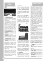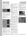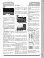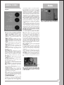
1
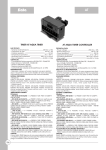
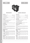
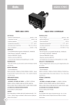
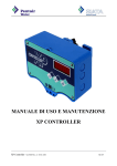
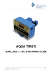
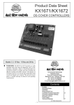
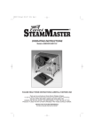
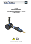
AQUA CUBIC
Siata
TIMER AQUA CUBIC
AQUA CUBIC CONTROLLER
DATI TECNICI
- Tensione di alimentazione: ____________________230 Vac ± 10%
- Frequenza di rete: __________________________ 50 Hz ± 3%
- Potenza assorbita: __________________________________ 4.6 VA
- Temperatura operativa: _______________________ 4° C – 40° C
- Dimensioni del contenitore: ______________ 165 x 127 x 70 mm
- Peso complessivo: __________________________ da 0,8 a 1,5 Kg
CERTIFICATI:
- Compatibilità Elettromagnetica 89/336/CEE , 93/68/CEE
- Bassa Tensione 73/23/CEE , 93/68/CEE
- Direttiva 2002/95/EC (RoHS)
- Direttiva macchine 98/37/CE
- Conformità dei materiali al DM 443/90 del 21.12.1990
RIGENERAZIONE:
- Manuale; Volume immediato duplex.
MODELLI DISPONIBILI:
- Filtrazione:
PS0465 AC5-02/05; PS0467 AC5-02/20 (tempi programmabili.
Durata minima ciclo 1 min, durata massima ciclo 99 minuti).
- Addolcimento:
PS0465 AC5-02/05; PS0467 AC5-02/20; PS0475 AC7-02/05
(tempi programmabili. Durata minima ciclo 1 min, durata
massima ciclo 99 minuti).
ABBINAMENTI POSSIBILI:
Filtrazione:
- AC5-02/05 & AC5-02/20 ----> PS0025 V132E (con eiettore per
filtro); PS0105 V240F; PS0135 V230E (con eiettore per filtro);
PS0161 V250F; PS0180 V260F; PS0200 V360F.
Addolcimento:
- AC5-02/05 & AC5-02/20 ----> PS0025 V132E; PS0085 V240A;
PS0135 V230E; PS0150 V250A; PS0155 V250A-NB; PS0165 V260A;
PS0185 V360A.
- AC7-02/05 ----> PS0025 V132E; PS0085 V240A; PS0135 V230E;
PS0150 V250A; PS0155 V250A-NB; PS0165 V260A; PS0185 V360A.
ACCESSORI DA ORDINARE SEPARATAMENTE
- PS1281 861-A CONNETTORE DIN PRESA A (180) per connessione
con contatore esterno
- PS1282 861-B CONNETTORE DIN PRESA B (270) utilizzabile con
AC5-02/20
- PS1283 861-C CONNETTORE DIN PRESA C (360) utilizzabile con
AC5-02/20
OPZIONI
Sono disponibili su richiesta altri tipi di trasformatore (Es. 115 /
12 Vac – 60 Hz). Prego contattare l' ufficio tecnico Hytek per
ulteriori informazioni.
TECHNICAL DATA
- Power voltage: ______________________________230 Vac ± 10%
- Network frequency: _____________________________ 50 Hz ± 3%
- Power absorbed: __________________________________ 4.6 VA
- Operative temperature: _______________________ 4° C – 40° C
- Container dimensions: ___________________ 165 x 127 x 70 mm
- Total weight: _____________________________ from 0,8 to 1,5 Kg
CERTIFICATIONS:
- Electromagnetic Compatibility 89/336/CEE , 93/68/CEE
- Low Voltage 73/23/CEE , 93/68/CEE
- Directive 2002/95/EC (RoHS)
- Directive macchine 98/37/CE
- All materials are according to al DM 443/90 of 21.12.1990
MODALITY OF REGENRERATION:
- Manual; Duplex Volumetric Immediate Regeneration Start.
AVAILABLE MODELS:
- Filtration:
PS0465 AC5-02/05; PS0467 AC5-02/20 (time cicles programmable,
time cicles minimum 1 min., time cicles max 99 min.).
Softener:
PS0465 AC5-02/05; PS0467 AC5-02/20; PS0475 AC7-02/05
(time cicles programmable, time cicles minimum 1 min., time
cicles max 99 min.).
POSSIBLE COMBININGS:
Filtration:
- AC5-02/05 & AC5-02/20----> PS0025 V132E (with filter injector);
PS0105 V240F; PS0135 V230E (with filter injector); PS0161 V250F;
PS0180 V260F; PS0200 V360F.
Softener:
- AC5-02/05 & AC5-02/20 ----> PS0025 V132E; PS0085 V240A;
PS0135 V230E; PS0150 V250A; PS0155 V250A-NB; PS0165 V260A;
PS0185 V360A.
- AC7-02/05 ----> PS0025 V132E; PS0085 V240A; PS0135 V230E;
PS0150 V250A; PS0155 V250A-NB; PS0165 V260A; PS0185 V360A.
ACCESSORIES TO BE ORDERED SEPARATELY
- PS1281 861-A DIN A CONNECTOR (180) for connection with
external liter counter
- PS1282 861-B DIN B CONNECTOR (270) usable with
AC5-02/20
- PS1283 861-C DIN C CONNECTOR (360) usable with
AC5-02/20
OPTIONS
Are available other types of transformer (Es. 115 / 12 Vac 60 Hz). Please contact Hytek Technical Office for further
information.
345
Siata
AQUA CUBIC
MANUALE DI SERVIZIO
Tasto
Nascosto
Fig. 1
1 – CARATTERISTICHE DI BASE
Aqua Cubic comanda valvole multivia
SIATA per la realizzazione di impianti di
trattamento acque.
Il ciclo di
rigenerazione è interamente
programmabile, ed è attivato in uno dei
seguenti modi:
- immediatamente all’esaurimento del
volume trattabile;
- manualmente tramite il tasto Manual
Regen.
Aqua Cubic è dotato di una memoria
eeprom dove viene memorizzata la
programmazione, e di una batteria
tampone che consente il mantenimento
in memoria dei parametri di lavoro in
caso di mancanza di tensione di
alimentazione. Aqua Cubic, come tutta
la gamma dei controller SIATA, è
conforme alle Direttive CEE ed è
realizzato nello Stabilimento SIATA di
Montespertoli, operante con il Sistema
Qualità certificato secondo la norma
ISO 9001 / UNI EN ISO 9001.
2 – SIGNIFICATO DEI LED E DEI TASTI
Funzionalità dei LED (Tab. 1)
- SERVICE A = Acceso quando è in servizio
la colonna A
- SERVICE B = Acceso quando è in servizio
la colonna B
Funzionalità dei tasti (Tab. 2)
- VOLUME SET = Consente l’accesso alla
rimessa del volume disponibile. Al termine
della programmazione, consente di
accedere alla programmazione dei
tempi del ciclo di rigenerazione.
- PROGRAM MODE = Consente di
accedere alle funzioni di
programmazione dei tempi del ciclo di
rigenerazione.
- ADVANCE = Premuto durante la
programmazione o la rimessa dell’ora,
consente di incrementare la cifra
lampeggiante sul display. Premuto
durante il servizio, consente l’accesso
alla diagnostica. (dalla ver. 9/98)
- METER DIVIDER = Consente l’accesso
alla rimessa del divisore del contatore
contalitri.
- MANUAL REGEN = Permette l’attivazione
manuale della rigenerazione. Premuto
durante una fase di stop, ne azzera il
tempo residuo e consente l’accesso alla
fase successiva del ciclo (Passo – Passo)
dalla ver. 9/98.
- RESET = Durante la programmazione,
consente di uscire senza salvare il
parametro in modifica al momento della
pressione del tasto. Durante la
rigenerazione, ne provoca la fine.
- TASTO NASCOSTO = Posizionato sotto i
6 tasti, al centro fra Advance e
Volume/Clock, consente di avviare una
rigenerazione di prova (Fasi da 1 min.).
Premuto durante alcune fasi della
programmazione, azzera la cifra
lampeggiante sul display.
346
3 - GENERALITÀ
Diamo qui di seguito alcune indicazioni
che devono essere rispettate durante
l’uso e la manutenzione del controller
allo scopo di garantirne una lunga vita
operativa.
3.1 – Imballo ed immagazzinamento
L’imballo è costituito da una scatola con
etichetta identificatrice del prodotto.
L’immagazzinamento dell’apparecchio
deve avvenire in ambienti con le seguenti
caratteristiche: - temperatura compresa
tra +4°C e +40°C; - umidità relativa tra 30
% e 95 %.
3.2 – Installazione
L’installazione del controller deve essere
effettuata da personale qualificato; le
procedure di installazione devono essere
eseguite ad apparecchio non
alimentato. L’apparecchio è costituito
da un box in ABS, chiuso frontalmente
da una mascherina fissata con 4 viti e
protetta da un coperchio trasparente.
Il controller è alimentato con un
trasformatore 230 / 12 Vac. Sono
disponibili su richiesta altri tipi di
trasformatore (Es. 115 / 12 Vac – 60 Hz).
Aqua Cubic ha il box forato sul lato destro
in corrispondenza del connettore DIN
180º (Fig. 11).
Fig. 3
Fig. 4
Nel caso si desideri alimentare i piloti
esterni del controller (Vedi Fig. 3 e 4) con
aria compressa, occorre accertarsi che:
• la pressione dell’aria di comando sia
compresa fra 1 e 6 bar, e comunque non
sia superiore alla pressione dell’acqua in
ingresso;
• sulla linea dell’aria di comando sia
montato un sistema di umidificazione
dell’aria (con acqua o adeguato
lubrificante siliconico), allo scopo di non
causare l’essiccamento delle guarnizioni
interne al pilota; SIATA raccomanda
sempre di alimentare i piloti con acqua.
In questo caso, occorre un filtro in ingresso
contro le impurità. Si consiglia di porre
particolare attenzione nella installazione
del controller in ambienti che non sono
conformi ai limiti contenuti nella norma
EN
50082-1
(compatibilità
elettromagnetica).
3.3 – Manutenzione
È buona norma, ogni 12 mesi circa,
eseguire un controllo sull’efficienza della
batteria come segue:
• Annotarsi il volume visualizzato sul
display, accertandosi che non sia uguale
al volume trattabile (visualizzabile
premendo il tasto Volume Set).
• Spegnere il timer per circa 15 minuti.
• Riaccendere il timer e controllare il
volume indicato dal display. Se invece
del volume che era stato annotato, il
display mostra il totale del volume
trattabile, la batteria deve essere sostituita
con il pezzo di ricambio cod. 867. Le
seguenti operazioni di manutenzione
devono sempre essere eseguite a
controller spento. In caso di sostituzione
della sola scheda elettronica ed ogni
qualvolta ci si trovi a dover agire sul box
aperto, evitare il più possibile di toccare
con le mani i componenti e le saldature,
soprattutto nella zona del
microprocessore, poiché eventuali
scariche elettrostatiche potrebbero
causare seri malfunzionamenti del
controller. Inoltre, è bene evitare di
appoggiare la scheda elettronica su un
piano di metallo a meno che non sia
adeguatamente isolata (sono sufficienti
un paio di fogli di carta). Per
l’immagazzinamento delle schede
elettroniche, usare sempre le buste
antistatiche dentro le quali vengono
consegnati i kit di ricambio. Evitare che
la scheda elettronica venga a contatto
con liquidi. Se questo avviene, procedere
alla sua asciugatura con getto d’aria.
3.4 – Dispositivi di protezione
Il controller è dotato delle seguenti
protezioni :
• Trasformatore di isolamento e sicurezza.
• Circuito elettronico di protezione dai
picchi di tensione e dai disturbi.
• Autoreset (dalla versione 9/98)
4 - ISTRUZIONI PER L’USO
4.1 – Accensione
Aqua Cubic non è dotato di interruttori
di alimentazione. L’accensione si ottiene
collegando il trasformatore di
alimentazione alla presa di corrente.
4.2 – Funzionamento
Dopo l’accensione, il display posto sul
pannello frontale visualizzerà il volume
disponibile. Alla prima accensione è
consigliabile non spegnere il controller
per almeno 24 ore consecutive, allo
scopo di evitare una carica anomala
alla batteria. La partenza della
rigenerazione è causata dall’esaurimento
del volume disponibile. Se non viene
connesso alcun sensore contalitri al
controller, è possibile avere la partenza
della rigenerazione esclusivamente
tramite il tasto Manual Regen.
4.3 – Programmazione
Si accede alla programmazione dei
tempi del ciclo di rigenerazione tramite
il tasto Program Mode, e i valori sono
modificabili con il tasto Advance. La
programmazione procede come segue:
Tabella programmazione (Tab. 3)
- 1 PROG. MODE = 2 0 0 0 Il volume
residuo. Il display rimane invariato.
- 2 VOLUME SET = 1 d 2 5 Il tempo di
rotazione della prima fase. Non
modificare.
- 3 PROG. MODE = 1 C 1 0 Il tempo di stop
della prima fase del ciclo di rigenerazione.
- 4 PROG. MODE = 2 d 2 5 Il tempo di
rotazione della seconda fase. Non
modificare.
- 5 PROG. MODE = 2 C 3 0 Il tempo di stop
della seconda fase del ciclo di
rigenerazione.
- 6 PROG. MODE = 3 d 2 5 Il tempo di
rotazione della terza fase. Non modificare.
- 7 PROG. MODE = 3 C 2 0 Il tempo di stop
della terza fase del ciclo di rigenerazione.
- 8 PROG. MODE = 4 d 2 5 Il tempo di
rotazione della quarta fase. Non
modificare.
- 9 PROG. MODE = 4 C 2 0 Il tempo di stop
della quarta fase del ciclo di
rigenerazione.
- 10 PROG. MODE = 5 d 0 0 Il tempo di
Siata
AQUA CUBIC
rotazione della quinta fase. Non
modificare.
- 11 PROG. MODE = 5 C 0 0 Il tempo di
stop della quinta fase del ciclo di
rigenerazione
- 12 PROG. MODE = 6 d 0 0 Il tempo di
rotazione della sesta fase. Non
modificare.
- 13 PROG. MODE = 6 C 0 0 Il tempo di
stop della sesta fase del ciclo di
rigenerazione
- 14 PROG. MODE = 7 d 0 0 Il tempo di
rotazione della settima fase. Non
modificare.
- 15 PROG. MODE = 7 C 0 0 Il tempo di
stop della settima fase del ciclo di
rigenerazione.
- 16 PROG. MODE = 8 d 0 0 Il tempo di
rotazione dell’ottava fase. Non
modificare.
- 17 PROG. MODE = 8 C 0 0 Il tempo di
stop dell’ottava fase del ciclo di
rigenerazione.
- 18 PROG. MODE = 8 C 0 0 La
programmazione è memorizzata in
eeprom.
Così programmato, Aqua Cubic realizza
un impianto duplex, dove le due colonne
si alternano in servizio e rigenerano una
alla volta. È possibile richiedere la versione
singola, dove le due colonne
componenti l’impianto sono
contemporaneamente in servizio e
vengono rigenerate in sequenza.
La rimessa del volume si ottiene con il
tasto Volume set, e procede come
segue:
Rimessa del volume (Tab. 4)
- 1 VOLUME SET = 0 2 0 0 Volume. Le cifre
di destra sono lampeggianti.
- 2 ADVANCE = 0 2 0 1 La modifica.
- 3 VOLUME SET = 0 2 0 1 Volume. Le cifre
di sinistra sono lampeggianti.
- 4 ADVANCE = 0 3 0 1 La modifica.
- 5 VOLUME SET = 0 2 0 0 Memorizzazione
del volume. Il display mostra il valore
precedente alle modifiche.
Il volume impostato con la procedura di
tab. 4 non diviene attiva al termine della
programmazione. Lo sarà solo dopo aver
premuto il tasto Reset o dopo aver
eseguito una rigenerazione. Per questo
motivo, una volta usciti dalla rimessa del
volume (passo 5 di Tab. 4), il display non
mostrerà il nuovo valore impostato ma il
volume residuo. La rimessa del divisore
del contatore si ottiene con il tasto Meter
divider e procede come segue:
Rimessa del divisore (Tab. 5)
- 1 METER DIV. = A A 0 1 Il divisore. La cifra
è lampeggiante.
- 2 ADVANCE = A A 0 2 La modifica del
divisore
- 3 METER DIV. = 0 2 0 0 Memorizzazione
del divisore. Il display mostra il volume.
Se si preme Reset in un qualunque
momento all’interno delle procedure
indicate nelle tabelle 3, 4 e 5, si esce
dalle procedure di programmazione
senza memorizzare le modifiche
apportate. Il Tasto nascosto consente
di azzerare il valore in modifica.
N.B. I valori indicati nella colonna Display
delle tabelle 3, 4 e 5 sono di esempio e
non sono vincolanti. Il controller può
presentare valori completamente diversi
da quanto indicato.
4.4 – Impianti particolari
Aqua Cubic, nella sua versione completa
(con 3 prese DIN, vedi fig. 9), consente
di controllare impianti con valvole SIATA
più valvole a diaframma, o impianti con
valvole a diaframma su richiesta
specifica.
4.5 – Messa in servizio Aqua Cubic, come
tutti i controller SIATA, è considerato in
servizio quando è in grado di eseguire la
rigenerazione. Questo è possibile SOLO
quando il controller “sente” che la
camma è correttamente posizionata a
fine corsa. Per poter eseguire delle prove
prima dell’installazione è necessario che
Aqua Cubic sia collegato al suo box, in
modo che l’ingresso dello switch di fine
corsa sia correttamente chiuso. Aqua
Cubic non consente alcuna operazione
fino a quando l’ingresso dello switch di
fine corsa non risulta chiuso. In riferimento
a quanto già indicato nel par. 4.3, una
volta modificata la programmazione di
Aqua Cubic è necessario premere il tasto
Reset o eseguire una rigenerazione per
poter caricare in memoria i nuovi
parametri.
4.7 – Gestione del volume
I passi di tab. 4 indicano la
programmazione del volume trattabile
Utilizzando il contalitri ad effetto Hall SIATA,
il valore del divisore (AA01, tab. 5) deve
essere programmato con il valore 14,
ovvero ogni 14 impulsi dal sensore si ha
il decremento medio non regolabile di
un litro dal volume disponibile. In questo
modo il massimo volume trattabile che
è possibile programmare risulta essere
10.000 litri. Se si ha l’esigenza di utilizzare
un volume superiore, è possibile ricorrere
ad una semplice operazione aritmetica,
ovvero raddoppiare, triplicare,
quadruplicare, ecc. il divisore e
contemporaneamente dividere per due,
per tre, per quattro, ecc. il volume
trattabile.
Esempi:
• Si devono trattare 15.000 litri di acqua:
- Volume/2 = 15.000/2 = 7500 nei passi 1
e 3 di tab. 4
- Divisore x 2 = AA14 x 2 = AA28 nel passo
2 di tab. 5
Nel momento dell’entrata in servizio il
volume trattabile sarà pari a 7500 litri.
• Si devono trattare 50.000 litri di acqua:
- Volume/5 = 50.000/5 = 0000 nei passi 1
e 3 di tab. 4
- Divisore x 5 = AA14 x 5 = AA70 nel passo
2 di tab. 5.
Nel momento dell’entrata in servizio il
volume trattabile sarà pari a 10000 litri (e
sarà visualizzato come 0000). Si fa
presente che programmare il volume con
il valore 0000, significa programmare
10.000, programmare il divisore con il
valore AA00, significa programmare il
divisore per 100. Il massimo volume
trattabile utilizzando il contalitri ad effetto
Hall SIATA è di 70.000 litri, programmando
10.000 litri di volume trattabile e AA98 di
divisore. Se si usa un contatore che
fornisce un impulso ogni litro (o metro
cubo), il massimo volume trattabile è di
1.000.000 litri (o metri cubi)
programmando 10.000 litri di volume
trattabile e AA00 di divisore
(corrispondente a 100 impulsi ogni litro o
metro cubo). E’ necessario segnalare
che, data la natura dei contatori Reed,
è sconsigliabile l’uso di contatori
1imp./1m3 o similari per le caratteristiche
di lettura del controller.
4.8 – Reset
Il controller può essere influenzato dai
seguenti eventi: la batteria scarica, una
perturbazione elettromagnetica
eccezionalmente forte (oltre i limiti imposti
dalla norma EN 50082-1), la
manipolazione della scheda con le mani,
un corto circuito fra le connessioni delle
prese DIN. Questi eventi possono causare
uno dei seguenti problemi; il “fuori
programma” o il “latch up”. Nel primo
caso la memoria RAM interna al
microcontrollore viene “sporcata”
dall’evento perturbatore con risultati
imprevedibili… si può avere il blocco
totale del controller, un comportamento
anomalo o ancora l’alterazione dei
parametri di funzionamento. Nel secondo
caso,
il
microcontrollore,
autonomamente, si porta in una
condizione particolare, denominata
appunto “latch up”, che gli consente di
proteggersi
da
potenziali
danneggiamenti. La differenza fra queste
due condizioni è che la prima, nella
maggioranza dei casi, viene risolta
autonomamente dal controller, grazie
ad un circuito di autoreset che interviene
dopo 5 secondi di anomalia dei segnali
del microcontrollore; la seconda richiede
sempre un intervento manuale. Le fig. 5
e 6 mostrano i punti dove intervenire per
risolvere le condizioni di blocco appena
indicate. La prima operazione da
eseguire quando il controller è
apparentemente spento, o quando si
comporta in maniera anomala, è il reset
cosiddetto “software”. Consiste nel
mettere in corto circuito per un attimo i
punti A1 e A2 indicati in fig. 6 quando il
trasformatore di alimentazione del
controller è connesso alla tensione di
rete. Se questa operazione non dà
risultati, si può procedere con il secondo
tipo di reset, il reset “hardware”. Consiste
nel tenere in corto circuito per qualche
secondo i punti B1 e B2 indicati in fig. 6
quando il trasformatore di alimentazione
del controller è staccato dalla tensione
di rete. Fatto questo, si deve collegare il
trasformatore di alimentazione alla
tensione di rete e verificare che il
controller si accenda subito o dopo i 5
secondi di intervento dell’autoreset. Se il
controller non si accende, ripetere il reset
“software” sui punti A1 e A2 di fig. 6. Se
il controller ancora non si accende,
consultare il Cap. 5.
Fig. 5
Fig. 6
4.9 – Connessioni
Fig. 7
347
Siata
AQUA CUBIC
Attraverso la presa DIN 180º visibile in fig.
7, Aqua Qubic può essere connesso ad
alcuni dispositivi esterni come segue:
• Contatti 1 – 3 = Volume, contatore
reed o con chiusura non alimentato.
• Contatti 1 – 5 – 3 = Volume, contatore
magnetico ad effetto Hall alimentato
dalla tensione +12 Vdc.
• Contatti 1 – 4 = Ingresso del segnale
di inibizione (in chiusura).
• Contatti 2 – 5 = Uscita del segnale
Impulso Fine Ciclo in modalità Open
Collector.
Fig. 8
I segnali Open Collector non possono
essere usati per controllare direttamente
l’accensione di utenze elettriche quali
elettrovalvole. Per poterlo fare, occorre
utilizzare un relè. In fig. 8 è visibile il
collegamento di un relè al segnale di
Impulso Fine Ciclo, in modalità Open
Collector. Il relè deve avere un
assorbimento massimo per l’eccitazione
della bobina di 20mA. Seguono i codici
di alcuni relè utilizzabili a questo scopo,
tutti con bobina da alimentare a 12 Vdc:
-Modello:
• OMRON G5V-1 12Vdc
• TAKAMISAWA MZ-12HS-U
• MATSUSHITA JQ1-12V o JQ1a-12V o
HD1-M-DC12V.
4.9.1 – Connessioni della versione con 3
prese DIN
Fig. 9
In fig. 9 sono indicate le connessioni
disponibili nella versione con 3 prese DIN,
da utilizzare come segue:
• DIN A, contatti 1 – 3 = Volume,
contatore reed o con chiusura, non
alimentato.
• DIN A, contatti 1 – 3 – 5 = Volume,
contatore magnetico ad effetto Hall
alimentato dalla tensione +12 Vdc.
• DIN A, contatti 1 – 4 = Ingresso del
segnale di inibizione (in chiusura).
• DIN A, contatti 2 – 5 = Uscita del segnale
di Impulso Fine Ciclo in modalità Open
Collector.
• DIN B, contatti 1 – 2 = Ingresso del
segnale di Start remoto (in chiusura).
• DIN C, contatti 2 – 3 = Uscita
normalmente aperta dell’impulso
348
durante la 2a fase del ciclo di rigeneraz.
• DIN C, 5 – 1 contatti = Uscita
nor malmente aperta dell’impulso
Rigenerazione in corso.
• DIN C, 5 – 4 contatti = Uscita
nor malmente chiusa dell’impulso
Rigenerazione in corso.
4.10 – Diagnostica
Aqua Cubic è dotato di un sistema di
diagnostica che consente all’addetto
alla manutenzione di conoscere lo status
funzionale del controller. Si accede a
questa funzione tramite il tasto Advance,
che va tenuto premuto per almeno 5-6
secondi. I parametri che verranno
visualizzati, sono i seguenti:
- F – 0 0 I = giorni trascorsi dall’ultima
rigenerazione.
- 0.0.0.0. = Il numero di rigenerazioni
effettuate
- 0 0 0 0 = Il volume consumato dall’ultima
rigenerazione. Il contatore di rigenerazioni
effettuate non può essere azzerato
dall’utente.
4.11 – Prova della partenza automatica
della rigenerazione
Per provare la partenza automatica della
rigenerazione, procedere come segue:
• In riferimento alla tab. 4, impostare 0002
come volume trattabile.
• Tramite il cavo sensore magnetico ed
una turbina SIATA, scalare il volume fino
a 0.
• Quando il volume giunge a 0, parte la
rigenerazione.
N.B. Per eseguire le prove indicate è
importante che il controller abbia il
micro_switch di fine corsa correttamente
collegato ed operativo. Per questo
motivo si raccomanda di usare il controller
montato nel suo box.
5 – RISOLUZIONE DEI PROBLEMI
Indichiamo alcune operazioni basilari per
la risoluzione dei piccoli problemi che
possono insorgere durante l’uso di Aqua
Cubic. Come regola generale
suggeriamo di verificare l’anomalia
presentata sostituendo la sola scheda
elettronica con una nuova o comunque
dal funzionamento sicuro (ovviamente
nei limiti delle possibilità pratiche). È
importante poter distinguere la causa
del malfunzionamento fra l’elettronica,
la meccanica o i cablaggi. La sostituzione
della scheda elettronica è già un valido
aiuto per l’individuazione della reale
causa del difetto.
Se i suggerimenti qui presentati non
riescono a dare la soluzione al problema,
Vi invitiamo a rivolgerVi al servizio
assistenza SIATA.
Il controller non si accende.
• Presa di alimentazione guasta. Spina
del trasformatore guasta. Trasformatore
guasto.
Verificare collegando un qualunque altro
tipo di apparecchio alla stessa presa ed
il controller ad un’altra presa.
• Problema di cablaggio. Aprire il box e
verificare che i fili siano correttamente
inseriti nel connettore 7 poli.
• Il controller è bloccato.
Se si usa la presa DIN laterale, verificare
che dentro la calotta del connettore non
ci siano morsetti in corto circuito. Seguire
le indicazioni del par. 4.8.
Il motore non si ferma sul fine corsa.
• Particolari in plastica danneggiati. Aprire
il box e verificare l’integrità delle parti in
plastica di sostegno al micro switch (Fig.
10).
• Micro switch danneggiato. Aprire il box
e verificare (Fig. 10): l’integrità del micro
switch; il suo corretto posizionamento; Il
corretto posizionamento dei morsetti;
l’integrità dei fili di collegamento;
l’integrità della leva di azionamento del
micro switch.
• La camma è fuori posizione. Aprire il
box (Fig. 10) e verificare che il seeger
metallico che trattiene la camma sia
integro e ben posizionato nel suo
alloggiamento. Verificare che la camma
azioni la leva del micro switch (ruotandola
a mano).
Il controller non rigenera.
• Il controller è programmato male.
Ve r i f i c a r e l a c o r r e t t e z z a d e l l a
programmazione, e che la modalità di
partenza della rigenerazione corrisponda
a quella effettivamente necessaria.
• Il controller è inibito. Se si sta usando la
presa DIN (Fig. 11), verificare che dentro
la calotta del connettore non ci siano
corto circuiti fra i morsetti.
Vengono visualizzati dei parametri errati.
• Il controller è fuori programma Occorre
resettare il controller, seguendo le
indicazioni del par. 6.8.
Fig. 10
In fig. 10 sono ben visibili il micro switch,
i suoi particolari meccanici di fissaggio
e comando, e i morsetti di collegamento
con il controller.
Fig. 11
In fig. 11 è visibile la presa DIN 180º dove
è possibile connettere la sonda contalitri.
Siata
AQUA CUBIC
SERVICE MANUAL
HIDDEN
KEY
Fig. 1
1 – GENERAL CHARACTERISTICS
Aqua Cubic controls the SIATA multi-way
valves for water treatment devices. The
regeneration cycle is completely
programmable. It can be enabled using
on of the following ways: As soon as the
treatable volume becomes exhausted;
Manually, by means of Manual Regen
key.
Aqua Cubic is provided with an EEPROM
that stores programming data, and a
buffer battery that allows working
parameters to be maintained in memory
when power is off.
Aqua Cubic, as well as all the SIATA
controllers, complies with the EC
Directives. It is assembled in the SIATA
factory in Montespertoli, Florence, Italy,
operating with its certified Quality System
according to ISO 9001 / UNI EN ISO 9001.
3 – MEANING OF LEDs AND KEYS
Meaning of LEDs (Tab. 1)
- SERVICE A ON = when column A is
working
- SERVICE B ON = when column B is
working
Meaning of keys (Tab. 2)
- VOLUME SET = Allows to change the
available volume. At the end of
programming, allows to set regeneration
cycle phases.
- PROGRAM MODE = Allows to program
regeneration cycle phases.
- ADVANCE = If pressed while in
programming or time setting, it increases
the digit currently blinking on the display.
If pressed on normal operations, it leads
to diagnostic functions (from ver. 9/98)
- METER DIVIDER = Allows to set the divider
of the liter counter. MANUAL REGEN
Allows to manually activate the
regeneration. If pressed while in stop, it
sets the residual time to zero and allows
to enter the next phase (step-by-step)
from version 9/98.
- RESET = Pressed while in programming
mode, it allows to quit without saving the
parameter currently edited. Pressed
during regeneration, it terminates it.
- HIDDEN KEY = It is located below the six
keys, centered between Advance and
Volume/Clock. It starts a test regeneration
(1 min. for each phase). If pressed during
some programming operations, it sets the
digit currently blinking to zero.
3 - GENERAL INFORMATION
Please find herewith below some
instructions to be followed during the
controller usage and maintenance in
order to ensure its long operating life.
3.1 – Packing and storage
The package consists in a box with a
product identification label. The device
must be stored in environments compliant
with the following characteristics: temperature from +4°C to +40°C; - relative
humidity from 30 % to 95 %.
3.2 – Installation
The controller installation must be
performed by qualified technical staff;
the installation procedures must be
per formed when the device is
disconnected from power. The device
consists in an ABS case closed on the
front side by a cover blocked with 4
screws, fixed with four screws and
protected by a transparent cover. The
controller is supplied by a 230/12 Vac
transformer. Different transformer types
(e.g. 115/12 VAC 60 Hz) are available
upon request. The case of Aqua Cubic
has a hole on the right side, near the DIN
180º connector (see Fig. 7).
Fig. 3
Fig. 4
Should you prefer to feed the controller
external drivers (see Fig. 3 and 4) with
compressed air, please verify that:
• The driving air pressure ranges from 1
to 6 bars. In no case the air pressure can
be higher than the input water pressure;
• An air humidification system (using water
or an adequate silicone lubricant) is
mounted on the pneumatic line. This is
required to prevent internal driver seals
from getting dry. SIATA recommends to
always supply drivers with water. In this
case it is necessary to use an input filter
to avoid impurities. Please be particularly
careful when installing the controller in
environments that are not compliant with
the EN 50082-1 standard (Electromagnetic
Compatibility).
3.3 – Maintenance
Please mind to check the battery
efficiency about every 12 months as
follows:
• Write down the volume shown on the
display. Verify that the value is not equal
to the treatable volume (you can access
it by pressing Volume Set).
• Turn the timer off for about 15 minutes.
• Turn the timer on. Read the value shown
on the display: if the display shows the
total treatable volume instead of the
value previously written, then replace the
battery using the spare part code 867.
The following servicing operations must
always be performed when the controller
is off power.
When replacing the sole electronic board,
and each time you must operate with
the case opened, avoid as much as
possible touching components and
welded parts with your hands, especially
near the CPU, since electrostatic
discharges could eventually cause serious
damages to the controller. Moreover, it
is better not to place the electronic board
on a metal surface, unless this has been
properly insulated (a few paper sheets
are enough).
To store electronic boards, always use
the anti-static envelopes that come with
the replacement kits.
Avoid the electronic board to come in
contact with liquids. Should this happen,
dry the board with an air jet.
3.4 – Safety devices The controller is
equipped with the following safety
devices:
• Safety and insulation transformer.
• Safety electronic circuit against voltage
peaks and disturbances.
• Autoreset (from version 9/98)
4 – INSTRUCTIONS FOR USE
4.1 – Powering on
Aqua Cubic is not provided with power
switches. Powering on is obtained by
plugging the power transformer into the
outlet.
4.2 – Working
After powering on, the display located
on the front panel shows the available
volume.
When powering on for the first time, it is
advisable not to switch off the controller
for at least 24 hours on end, in order to
avoid an anomalous battery charge.
The activation of the regeneration
process is triggered after the available
volume becomes exhausted.
If a liter counter sensor is not connected
to the controller, then the regeneration
can only start by pressing the Manual
Regen key.
4.3 – Programming
mode Pressing the Program Mode key
accesses programming of regeneration
cycle times. Pressing the Advance key
changes values. Proceed as follows:
Programming table (Tab. 3)
- 1 PROG. MODE = 2 0 0 0 Remaining
volume. Display does not change.
- 2 VOLUME SET = 1 d 2 5 Rotation time
for the first phase. Do not modify.
- 3 PROG. MODE = 1 C 1 0 Stopping time
for the first regeneration phase.
- 4 PROG. MODE = 2 d 2 5 Rotation time
for the second phase. Do not modify.
- 5 PROG. MODE = 2 C 3 0 Stopping time
for the second regeneration phase.
- 6 PROG. MODE = 3 d 2 5 Rotation time
for the third phase. Do not modify.
- 7 PROG. MODE = 3 C 2 0 Stopping time
for the third regeneration phase.
- 8 PROG. MODE = 4 d 2 5 Rotation time
for the fourth phase. Do not modify.
- 9 PROG. MODE = 4 C 2 0 Stopping time
for the fourth regeneration phase.
- 10 PROG. MODE = 5 d 0 0 Rotation time
for the fifth phase. Do not modify.
- 11 PROG. MODE = 5 C 0 0 Stopping time
for fifth regeneration phase.
- 12 PROG. MODE = 6 d 0 0 Rotation time
for the sixth phase. Do not modify.
- 13 PROG. MODE = 6 C 0 0 Stopping time
for the sixth regeneration phase.
- 14 PROG. MODE = 7 d 0 0 Rotation time
for the seventh phase. Do not modify.
- 15 PROG. MODE = 7 C 0 0 Stopping time
for the seventh regeneration phase.
- 16 PROG. MODE = 8 d 0 0 Rotation time
for the eighth phase. Do not modify.
- 17 PROG. MODE = 8 C 0 0 Stopping time
for the eighth regeneration phase.
- 18 PROG. MODE = 8 C 0 0 New values
are stored into the EEPROM.
Programmed as shown, Aqua Cubic is a
double-working device, where the two
columns work alternatively and are
regenerated one at a time. It is possible
to request the single version, where both
columns composing the device work at
349
Siata
the same time and are regenerated in
sequence.
To set the volume, press the Volume set
key and proceed as follows:
Volume setting (Tab. 4)
- 1 VOLUME SET = 0 2 0 0 Volume.
The digits on the right-hand side blink.
- 2 ADVANCE = 0 2 0 1 Setting.
- 3 VOLUME SET = 0 2 0 1 Volume. The
digits on the left-hand side blink.
- 4 ADVANCE = 0 3 0 1 Setting.
- 5 VOLUME SET = 0 2 0 0 Volume storage.
The display shows the value as before
the changes.
The volume set following the procedure
of tab. 4 does not become active at the
end of the programming.
It becomes active only by pressing the
Reset key or after a regeneration process.
Thus, after setting the volume (step 5 of
Tab. 4), the display shows the residual
volume and not the volume just set.
To set the divider of the counter, press
the Meter divider key and proceed as
follows:
Divider setting (Tab. 5)
- 1 METER DIV. = A A 0 1 Divider. The value
blinks.
- 2 ADVANCE = A A 0 2 Setting operation.
- 3 METER DIV. = 0 2 0 0 Divider storage.
The display shows the new value.
Any time you press Reset while executing
the procedures of tables 3, 4 and 5, you
will exit the programming procedures
without saving the changes.
The Hidden key allows to set the edited
value to zero.
NOTE: The values shown in the column
Display of tables 3, 4 and 5 are only
examples.
The controller can display values
completely different from those indicated
here.
4.4 – Special systems
The full version of Aqua Cubic (with 3 DIN
plugs, see fig. 9) allows you to control
systems with SIATA valves and diaphragm
valves, or systems with diaphragm valves
on specific request.
4.5 – Normal operations
Aqua Cubic, as well as the other SIATA
controllers, is considered “on duty” when
it is able to accomplish a regeneration.
This is possible ONLY when the controller
“senses” that the cam is correctly
positioned at the limit stop. To perform
some tests before installation, Aqua
Cubic must be connected to its case, so
that the limit switch be correctly closed.
Aqua Cubic does not allow any
operation until the limit switch input is
closed. As already indicated in 4.3, after
programming Aqua Cubic press the
Reset key or perform a regeneration
process in order to transfer the new
parameters into the memory.
4.6 – Managing the volume
Steps of tab. 4 show how to program the
treatable volume. If you use the Hall
effect-based, SIATA liter counter, then set
the divider (AA01, tab. 5) to 14, that is,
every 14 impulses the available volume
is decreased by an average, non
settable amount of one liter.
Thus the maximum programmable
volume is 10.000 liters. If you need to use
a larger volume, then use a simple
arithmetical operation by multiplying the
divider by two, three, four and so on.
At the same time, divide the treatable
volume by two, three, four and so on.
For example:
• 15.000 liters of water must be treated:
- Volume/2 = 15.000/2 = 7500 in steps 1
and 3 of tab. 4
- Divider x 2 = AA14 x 2 = AA28 in step 2
of tab. 5
350
AQUA CUBIC
When the device begins working, the
treatable volume will be 7500 liters.
• 50.000 liters of water must be treated.
- Volume/5 = 50.000/5 = 0000 in steps 1
and 3 of tab. 4
- Divider x 5 = AA14 x 5 = AA70 in step 2
of tab. 5.
When the device begins working, the
treatable volume will be 10000 liters
(displayed as 0000).
Please note that Setting the volume to
0000 means setting it to 10.000. Setting
the divider to AA00, means setting it to
100. The maximum treatable volume
when using the Hall effect-based, SIATA
liter counter is 70.000 liters, obtained by
setting the treatable volume to 10.000
liters and the divider to AA98. If you use
a counter issuing one impulse each liter
(or cubic meter), the maximum treatable
volume is 1.000.000 of liters (or cubic
meters). To do so set the treatable volume
to 10.000 liters and the divider to AA00
(this corresponds to 100 impulses each
liter or cubic meter). Please note that,
given the nature of the Reed counters,
the usage of counters type 1 impulse/1
m3 or similar is discouraged.
4.7 – Reset
Several events may influence the
controller: battery exhausted, very high
electromagnetic disturbance (beyond
the limits established by the EN 50082-1
standard), handling the electronic board,
a short circuit between connections or
DIN sockets.
Such events may cause one of the
following problems: the “out of program”
and the “latch up”. In the first case, the
RAM on the CPU becomes “dirty” due to
the disturbing event. The results are
unpredictable: for example, complete
failure of the controller, abnormal
behavior, or the alteration of working
parameters.
The second case happens when the CPU
autonomously turns its state to “latchup”, a special condition that allows it to
be protected against potential damages.
The difference consists in the fact that
the first condition is mostly autonomously
solved by the controller thanks to an
autoreset circuit that becomes active
when it is not receiving any signal from
the micro-controller for at least 5 seconds
of anomalous microcontroller signals. The
second condition always requires a
manual intervention.
Figures 5 and 6 show where it is necessary
to intervene in order to solve the above
mentioned conditions. The first operation
to be performed when the controller is
apparently off, or when its behavior is
anomalous, is the so called “software
reset”.
It consists in short-circuiting for a while
points A1 and A2 shown in fig. 6, when
the controller supply transformer is
connected to the supply voltage.
If this operation gives no results, proceed
with the second reset type: the “hardware
reset”.
It consists in short-circuiting for 5 seconds
points B1 and B2 shown in fig. 6, when
the controller supply transformer is
disconnected from the supply voltage.
Once this operation is completed,
connect the supply transformer to the
supply voltage and check that the
controller powers on immediately or after
the 5 seconds necessary for the autoreset.
If the controller does not power on, repeat
the “software reset ” on points A1 and
A2 shown in fig. 6. If the controller still
remains off, please refer to Chap. 5.
Figures 5 and 6 show the points involved
in the reset procedure.
Fig. 5
4.8 – Connections
Fig. 6
Fig. 7
Through the 180º DIN socket, shown in fig.
7, Aqua Cubic can be connected to
some external devices as follows:
• Contacts 1 – 3 = Volume, reed counter
or with closing not powered.
• Contacts 1 – 5 – 3 = Volume, magnetic
counter to Hall effect powered by the
tension +12 Vdc.
• Contacts 1 – 4 = Input of the signal of
inhibition (in closing).
• Contacts 2 – 5 = Output of the signal
Limit cycle impulse in Open Collector
mode.
Fig. 8
Fig. 8 shows the correct usage of Cycle
End Impulse, available as Open Collector.
The relays should not exceed a maximum
coil activation current of 20mA.
Below are the codes of some relays that
can be used for this purpose.
They all have a coil voltage of . Builder
Model:
- OMRON G5V-1 12Vdc
- TAKAMISAWA MZ-12HS-U
- MATSUSHITA JQ1-12V or JQ1a-12V or
HD1-M-DC12V.
Siata
AQUA CUBIC
4.9.1 – Connections of the version with 3
plug DIN
Fig. 9
Fig. 9 shows the connections available
with the model provided with 3 DIN
sockets. They can be used as follows:
• DIN A, 1–3 contacts = Volume, counter
reed or with closing not powered.
• DIN A, 1–3–5 = Volume, Hall effect
magnetic counter powered by the
tension +12 Vdc.
• DIN A, 1–4 = Input of inhibit (in closing).
• DIN A, 2–5 = Output of the signal of limit
cycle impulse in Open Collector mode.
• DIN B, 1–2 = Input of remote starter (in
closing).
• DIN C, 2–3 = Output normally opened
of the impulse during the 2nd phase of
regener. Cycle.
• DIN C, 5–1 = Output normally opend
of the impulse of the regeneration in
progress.
• DIN C, 5–4 = Output normally closed of
the impulse of the regeneration in
progress.
4.9 – Diagnostics
Aqua Cubic has a diagnostic system,
that the maintenance personnel can use
to learn the status of the controller. To
access this function, press and hold the
Advance key for at least 5-6 seconds.
The following parameters will be
displayed:
- F – 0 0 = Days elapsed since the last
regeneration.
- 0.0.0.0. = Number of regeneration
processes performed.
- 0 0 0 0 = Volume consumed since the
last regeneration process.
The counter counting the performed
regeneration processes cannot be reset
by the user.
4.10 – Testing the regeneration automatic
start
To test the regeneration autostart
function, proceed as follows:
• With reference to tab. 4, set 0002 as
treatable volume.
• Using the magnetic sensor cable and
a SIATA turbine, reduce the volume to 0.
• After the volume has reached 0, the
regeneration should start.
NOTE: To perform these tests, the limit
micro-switch of the controller must be
correctly connected and working. Thus,
it is recommended to use the controller
when installed in its case.
5 – TROUBLESHOOTING
Here are some basic troubleshooting
operations to solve those small problems
that can arise while using Aqua Cubic.
As a general rule it is suggested,
whenever possible, to check the problem
by replacing the sole electronic board
with another one, new or certainly
working. It is important to understand
whether the problem comes from
electronics, mechanics, or wiring harness.
Replacing the electronic board may be
a precious help to identify the real cause
of the defect. If our suggestions are not
sufficient to solve your problems, please
contact the SIATA assistance department.
The controller does not power on
• Outlet out of order. Transformer plug
out of order. Transformer out of order.
Check the problem by connecting any
other device to the same outlet, and by
connecting the controller to another
outlet.
• Wiring harness problems. Open the
case. Check that the wires are correctly
mounted in the 7-pole connectors
• The controller is blocked. If you use the
DIN lateral socket, verify that inside the
connector there are no short-circuited
terminals. Follow the instructions in 4.9
The motor does not stop after reaching
the limit stop position.
• The plastic parts are damaged. Open
the case. Verify the integrity of the plastic
parts that hold the microswitch (see Fig.
10).
• The microswitch is damaged. Open the
box and check (Fig. 10): integrity of
microswitch; correct placement of
microswitch; correct placement of
terminals; integrity of wires; integrity of
the lever that activates the microswitch.
• The cam is out of place. Open the case
(Fig. 10). Verify that the Seeger ring that
locks the cam is integer and correctly
placed in its housing. Moving the cam
with your hands, verify that it activates
the microswitch lever.
The controller does not per form
regeneration
• The controller is not correctly
p r o g r a m m e d . Ve r i f y t h a t t h e
programming has been performed
correctly. Verify that the regeneration
start mode corresponds to that really
needed.
• The controller is inhibited. If you use the
DIN socket (Fig. 11), verify that inside the
connector there are no short-circuited
terminals
The display shows wrong parameters.
• Controller is in “out of program”. Reset
the controller, following the instructions in
4.8
Fig. 11
Fig. 11 shows the DIN 180º socket, where
a liter counter sensor can be connected
Fig. 10
Fig. 10 clearly shows the microswitch, the
mechanical parts for mounting and
command, and the terminals connecting
to the controller.
351