1
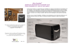
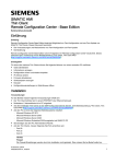
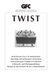
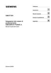
SIMODRIVE POSMO SI Benutzerhandbuch Deutsch Bestell–Nr. (MLFB): 6SN2197–0AA20–0AP : Platzhalter für Ausgabestand SIMODRIVE POSMO SI 600 V DC – Anschlussspannung supply voltage Montageanleitung mit PROFIBUS-Einheit ECOFAST Ausgabe 07.05 Assembly Instructions with the PROFIBUS unit ECOFAST Edition 07.05 User Manual Order No. (MLFB): English 6SN2197–0AA20–0BP : space for edition Anschlussplan und Verdrahtung PROFIBUS-Einheit / Connection diagram and wiring of PROFIBUS unit 1 PROFIBUS + optional Elektronikstromversorgung / PROFIBUS + electronics power supply (optional) 2 Eingänge / inputs (X23) 3 Ausgänge / outputs (X24) 0V Elektronikstromversorgung (geschaltet) electronics power supply (switched) (z. B. / e. g.: SITOP power, optional) +24 V 1) 1 1 0V 3 2 Elektronikstromversorgung (nicht geschaltet) electronics power supply (non-switched) (z. B. / e. g.: SITOP power, optional) +24 V +24 V 0V 3 Schrauben 3 screws M4 x 16 1 1 0V +24 V Eingänge inputs 4 3 nc 2 1 4 3 nc 2 1 zum nächsten Antrieb to the next drive Ausgänge outputs PROFIBUS-Einheit PROFIBUS unit M5 x 8 Achtung / Notice M12-Steckverbindung vollständig einschrauben (Einschraubtiefe 7 mm). Please ensure the crew-in depth for M12 plug-in connection 7 mm. B I1.A 2 3 M 3 M 3 5 4 O1.A 2 A A: PROFIBUS Daten / data A 5 4 1 I0.A O0.A z. B. Relais 1 e. g. relay 1 z. B. Relais 2 e. g. relay 2 PROFIBUS Abschlusswiderstand Teilnehmeradresse terminating resistor node address OFF=0 Pinbelegung / pinout B: PROFIBUS Daten / data B 1 VS X24 B 1: +24 V nicht geschaltet / non-switched 20 = 1 21 = 2 22 = 4 23 = 8 24 = 16 25 = 32 26 = 64 X23 2 A ON / OFF ON / OFF ON / OFF ON / OFF Hinweis / Note Potentialausgleichsleitung parallel zum PROFIBUS verlegen. Potential bonding conductor run in parallel to PROFIBUS. 4 mm2 Blindstopfen Dummy plug (––> M12) ON=1 Schaltereinstellung switch setting 2: 0 V nicht geschaltet / non-switched 3: 0V geschaltet / switched 4: +24 V geschaltet / switched ON 1 2 3 4 ON 1 2 3 4 5 6 7 8 1. Standard herstellen 1. use standard setting nc: optional common ground z. B. / e. g. BERO 1 Abschlusswiderstand / terminating resistor = OFF z. B. / e. g. BERO 2 Hinweis / Note BERO beim Referenzieren ist an PIN 4 anzuschließen! BERO must be connected to PIN 4 when referencing! Teilnehmeradresse / node address = 37 ON 1 2 3 4 OFF ON 1 2 3 4 5 6 7 8 1+ 4 + 32 2. Beispiel 2. example = 37 Hinweis / Note 1) Bei letztem PROFIBUS-Teilnehmer Schutzkappe auf Ausgangsstecker lassen / For the last PROFIBUS node, leave the protective cap fitted on the output plug. Siemens AG 2005 All Rights Reserved GWE–Nr. / GWE No.: A5E00335557 ab Hotline Tel. / Fax: +49 (0)180 / 5050 – 222 / 223 E-mail: [email protected] nicht maßstäblich / not to scale Maße in mm / Dimensions in mm SIMODRIVE POSMO SI Montageanleitung mit PROFIBUS-Einheit ECOFAST Ausgabe 07.05 Assembly Instructions with the PROFIBUS unit ECOFAST Edition 07.05 Anschlussplan und Verdrahtung / Connection diagram and wiring SIMODRIVE POSMO SI 4 Laststromversorgung Load power supply 5 Energiezuführung, z. B. SIMODRIVE 611 Netzeinspeisemodul Power supply e.g. via SIMODRIVE 611 power supply module 6 Klemme “Impulsfreigabe” (KL IF) 3 Gewindebohrungen zum Terminal “pulse enable” (KL IF) Abstützen des Motors und für Hebeösen 3 thread holes for supporting PROFIBUS-Einheit the motor and for lifting eye P600 PROFIBUS unit 5 M8 x 16 3 Schrauben 3 screws M600 M4 x 16 U1 V1 W1 Important Instructions 1. Vor der Inbetriebnahme sind die Hinweise im aktuellen Benutzerhandbuch zu beachten. Bestelldaten hierfür entnehmen Sie bitte den Katalogen oder wenden Sie sich an Ihre örtliche SIEMENS-Niederlassung. Die Inbetriebnahme ist so lange untersagt, bis festgestellt wurde, dass die Maschine, in die diese Komponente eingebaut werden soll, den Bestimmungen der Richtlinie 98/37/EG entspricht. 1. 2. Alle Arbeiten dürfen nur von qualifiziertem Fachpersonal durchgeführt werden. Vor Beginn jeder Arbeit am SIMODRIVE POSMO SI müssen die 5 Sicherheitsregeln beachtet werden: Freischalten, gegen Wiedereinschalten sichern, Spannungsfreiheit feststellen, Erden und Kurzschließen und benachbarte unter Spannung stehende Teile abdecken oder abschranken. 3. 4. 5. 6. 7. PE1 8. 6 1) 1) 9. 10. Z 2 1 11. 12. KL IF 1) M24 C D FN 1 3 sw/bk 2 4 ws/wh PE gnge/grye W/L3/D/L– sw/bk Netzanschluss Power supply 3 x AC 400 / 480 V sw/bk U/L1/C/L+ Z 13. PE M5 x 12 Entstörfilter2) Interference suppression filter2) 16. SUPPLY IN PE 2 1 M24 KL IF 4 SUPPLY OUT C C C C D D D D 1 2 KL IF M24 PE 4 Hinweis / Note zum nächsten Antrieb to the next drive 1) Projektierungshinweise zur Sicherung siehe Benutzerhandbuch. For notes on design of fuse please refer to user manual. 2) Zur Erhöhung der Störfestigkeit gegen transiente Störungen (Burst) und zur Einhaltung der Grenzwerte der EN 61000–6–2 ist der beschriebene, beiliegende Entstörfilter an der Eintrittstelle in das geschirmte Kabel mit einer kurzen Anbindung (<15 cm) gegen PE einzusetzen. To increase the noise immunity against transient faults (burst) and to comply with the limit of EN 61000–6–2, the interfrence suppressor filter described and included has to be inserted at the entry point in the shield cable using a short PE connector (<15 cm). Siemens AG 2005 All Rights Reserved GWE–Nr. / GWE No.: A5E00335557 ab 14. 15. Steckeranschluss / Plug connection SIMODRIVE POSMO SI User Manual Order No. (MLFB): Wichtige Hinweise Speicherbaugruppe Memory module LK Benutzerhandbuch Deutsch Bestell–Nr. (MLFB): 6SN2197–0AA20–0AP : Platzhalter für Ausgabestand SIMODRIVE POSMO SI 600 V DC – Anschlussspannung supply voltage 17. ! Gefahr Danger Vorsicht beim Anfassen! Beim SIMODRIVE POSMO SI können während des Betriebs Oberflächentemperaturen von über 100 C auftreten! Brandgefahr! Leitungsschirme und nicht benutzte Adern von Leistungsleitungen müssen auf PE-Potential gelegt werden. Bei Nichtbeachtung können lebensgefährliche Berührungsspannungen entstehen. Die Zwischenkreisankopplung ist zum Schutz vor Restspannung mit einer Sicherheitsverrieglung versehen, die nur mit Werkzeug, z. B. Schraubendreher, von qualifiziertem Personal zu öffnen ist. Das Ziehen der Zwischenkreisankopplung darf frühestens 30 min nach Abschalten der Versorgungsspannung erfolgen! Das Gerät erzeugt einen hohen Ableitstrom und ist für einen festen, nichtortsveränderlichen Anschluss vorgesehen. Zusätzlich zum Schutzleiter in der Netzzuleitung ist ein zweiter Schutzleiter mit einem Mindestquerschnitt von Warnung 6 mm2 an den PE-Schraubanschluss am Gerätegehäuse mit der vorhandenen korrosionsgeschützten Schraube M5 und Kontaktscheibe anzuschließen. Warning Schutzeinrichtungen auch beim Probebetrieb nicht außer Funktion setzen. Bei Wellenende mit Passfeder ist beim Probebetrieb ohne Abtriebselemente die Passfeder zu sichern. Drehrichtung im ungekuppelten Zustand kontrollieren. Für Transport und Montage geeignete Lastaufnahmemittel verwenden. Die Verriegelungshebel für die Leistungsanschlüsse dürfen nicht zum Heben und Transportieren verwendet werden. Achtung, elektrotatisch gefährdete (EGB) Bauelemente vorhanden! Die PROFIBUS-Einheit darf nur bei abgeschalteter Energiezuführung gezogen und gesteckt werden. Die Einspeisung 24 V extern für Elektronik bleibt wegen der PROFIBUS-Kommunikation für nachfolgende Teilnehmer erhalten. Ein Anschluss an das Drehstromnetz führt zur Zerstörung des Gerätes. Beim Einbau des SIMODRIVE POSMO SI mit Wellenende nach oben muss gewährleistet werden, dass keine Flüssigkeit in das obere Lager eindringen kann. Beim SIMODRIVE POSMO SI mit integrierter Haltebremse sind keine axialen Kräfte zulässig. Die Bremse ist auf ihre einwandfreie Funktion zu überprüfen. Der Einsatz als Arbeitsbremse ist nicht zulässig. Vorsicht Bei extremen Schwingbeanspruchungen muss der Motor über die drei Caution M8-Gewindebohrungen mit einer entsprechenden Halterung abgestützt werden. Um die Schutzart zu gewährleisten, müssen alle Anschlüsse mit einem Blindstopfen oder mit einer M-Verschraubung abgedichtet sein. Beim Auf- und Abziehen von Abtriebselementen auf die Abgangswelle dürfen keine Schläge (z. B. mit einem Hammer) oder größere als die maximal zulässige Axial- oder Radiallast auf das Wellenende wirken. Die Belüftung am SIMODRIVE POSMO SI darf nicht behindert werden. Luftwege regelmäßig reinigen. ! 18. Auf gute Flanschbefestigung und genaue Ausrichtung achten. Die Flanschbefestigung ist für Innensechskantschrauben ausgelegt. Bei erhöhten Geräuschen/Schwingungen/Temperaturen abschalten und prüfen. 19. Das Antriebsgerät ist über den Schutzleiter der Leistungsleitung geerdet. Achtung Der Schirm der Leistungsleitung ist an der Energieversorgung mit Schlauchschelle an geeigneter Schirmauflagstelle zu befestigen. Notice Empfehlung: Parallel zur PROFIBUS-Leitung Potentialausgleich verlegen 2 (Leitungsquerschnitt 4 bis 16 mm ). 20. Beim Einsatz von SIMODRIVE POSMO SI in UL-zugelassenen Anlagen sind die UL-Hinweise im Benutzerhandbuch zu beachten. 21. Diese Montageanleitung enthält nur Informationen zum Montieren und Verdrahten des SIMODRIVE POSMO SI. 22. Alle Leistungsschilder, Warnschilder und Hinweisschilder am SIMODRIVE POSMO SI sind zu beachten! 23. Für die Verdrahtung des SIMODRIVE POSMO SI sind konfektionierte Leitungen nach Siemens-Katalog NC Z einzusetzen. Hinweis 24. Das Öffnen der Geräte ist untersagt! Reparatur- und Instandhaltungsarbeiten Note sind von einem SIEMENS-Servicezentrum durchzuführen. 25. Nach der Lebensdauer des Produktes sind die einzelnen Teile entsprechend den landesspezifischen Vorschriften zu entsorgen. 26. Weitere Hinweise, z. B. zum Gerätetausch und zur Firmwarehochrüstung sind dem aktuellen Benutzerhandbuch des Produktes zu entnehmen. Hotline Tel. / Fax: +49 (0)180 / 5050 – 222 / 223 E-mail: [email protected] 2. 3. 4. 5. 6. 7. 8. 9. English 6SN2197–0AA20–0BP : space for edition Prior to startup you must observe the notes in the current user manual. For ordering data of the documentation please refer to catalogs or contact your local SIEMENS representative. Startup must not take place until it is established that the machine, which is to accomodate this component, is in conformity with the directive 98/37/EC. Any work must only be performed by qualified experts. Before you start working on the SIMODRIVE POSMO SI, you must take care to ensure the 5 safety rules: Isolate, protect against restart, check absence of power, ground and short-circuit and cover or safeguard adjacent parts which are under voltage. Be careful when touching the devices! Surface temperatures of more than 100 C may occur on SIMODRIVE POSMO SI during operation! Danger of fire! Cable shields and unused cores of power cables must be connected to protective earth. Otherwise highly dangerous contact voltages may occur. In order to protect the dc link from residual voltage, it has been provided with a safety lock that can only be opened by qualified personnel using tools such as screwdrivers. The dc link may be decoupled only 30 min. after switching off the supply voltage at the earliest! The unit generates a high leakage current and is provided for a fixed-location connection. In addition to the protective conductor in the mains supply cable, you must connect a second protective conductor with a minimum cross-section of 6 mm2 to the PE screw connection at the unit housing with a existing corrosion-protected M5 screw and contact washer. Do not disable the function of the protective devices during test mode. If the shaft end has a featherkey, secure the featherkey during test mode without output elements. Check the direction of rotation when it is disengaged. Please use the appropriate load carrying devices for transport and installation. The locking levers for the load connections must not be used to lift and transport the unit. Caution, electrostatically sensitive devices (ESD) present. 10. The power supply must be switched off before the PRIFIBUS unit is withdrawn or inserted. The external 24–V supply for the electronics is maintained for PROFIBUS communication with participant. 11. It is not allowed to connect the system to a three-phase mains – this may destroy the device. 12. When installing the SIMODRIVE POSMO SI with the shaft end above, please ensure that no liquids can penetrate into the upper bearing. 13. No axial forces may affect the SIMODRIVE POSMO SI with integrated retaining brake. You must ensure proper functioning of the brake. The brake must not be used as working brake. 14. In the case of extreme vibration loads, the motor must be supported with the corresponding holder via the three M8 thread holes. 15. In order to guarantee the degree of protection, all connections must be sealed with a dummy plug or a M gland. 16. When inserting and removing output elements on the output shaft, no impacts (for example using a hammer) or axial or radial loads exceeding the maximum admissible ones may act on the shaft end. 17. The ventilation on the SIMODRIVE POSMO SI must not be impeded. If very much dirt is produced, we recommend that you clean the air outlets regularly. 18. Ensure a good fixation of the flange and an exact orientation. The flange fixture is designed for Allen screws. In the case of excessive noise/oscillation/temperature, you switch the system off and examining. 19. The drive unit is earthed via the protective conductor of the power cable. The shield of the power cable must be fixed with a tube clip to the power supply unit at an appropriate shield bearing position. Recommendation: Lay equipotential bonding conductor (cross-section 4 to 16 mm2) parallel to PROFIBUS cable. 20. When using the SIMODRIVE POSMO SI in systems with UL approval, please read the respective UL notes given in the user manual. 21. These assembly instructions contain only information on installing and wiring the SIMODRIVE POSMO SI. 22. Please observe all rating plates, warning labels and notes attached to the SIMODRIVE POSMO SI! 23. Cables pre-assembled acc. to the Siemens Catalog NC Z must be used for wiring the SIMODRIVE POSMO SI. 24. You are not allowed to open the devices! We recommend that your responsible SIEMENS service center performs the repair and maintenance work. 25. When the service life of the product has expired, the individual parts must be disposed according to the country-specific regulations. 26. Further information. e.g. on replacing the device and on upgrading the firmware, can be found in the current product user manual. nicht maßstäblich / not to scale Maße in mm / Dimensions in mm SIMODRIVE POSMO SI Montageanleitung mit PROFIBUS-Einheit ECOFAST Ausgabe 07.05 Assembly Instructions with the PROFIBUS unit ECOFAST Edition 07.05 Benutzerhandbuch Deutsch Bestell–Nr. (MLFB): 6SN2197–0AA20–0AP : Platzhalter für Ausgabestand SIMODRIVE POSMO SI 600 V DC – Anschlussspannung supply voltage User Manual Order No. (MLFB): English 6SN2197–0AA20–0BP : space for edition Avvertenze importanti 1. ! Pericolo di morte Danger 2. 3. 4. 5. ! 6. Pericolo Warning 7. 8. 9. Attenzione Caution Avviso Notice Avvertenza Note Siemens AG 2005 All Rights Reserved GWE–Nr. / GWE No.: A5E00335557 ab Hotline Tel. / Fax: +49 (0)180 / 5050 – 222 / 223 E-mail: [email protected] Prima della messa in servizio si devono osservare le avvertenze contenute nel manuale utente più aggiornato il cui numero di ordinazione può essere desunto dai cataloghi del prodotto oppure può essere richiesto alla più vicina rappresentanza Siemens. La messa in servizio è proibita fino a quando non venga stabilito che la macchina sulla quale deve essere installatoquesto componente risponde alle prescrizioni della direttiva 98/37/UE. Tutti i lavori devono essere eseguiti solo da personale tecnico qualificato. Prima di iniziare qualsiasi lavoro sul SIMODRIVE POSMO SI si devono rispettare le 5 regole di sicurezza: togliere tensione, assicurarsi contro il riavviamento accidentale, stabilire con certezza l’assenza di tensione, mettere a terra e cortocircuitare e coprire o proteggere parti adiacenti che si trovano sotto tensione. Attenzione nel toccare l’apparecchiatura! Il SIMODRIVE POSMO SI durante il funzionamento può raggiungere una temperatura sulla superficie esterna di oltre 100 C! Pericolo di incendio! Gli schermi dei cavi e i conduttori dei cavi non utilizzati devono essere collegati con il potenziale di terra. Se non si osserva questa avvertenza potrebbero verificarsi tensioni di contatto pericolose per l’incolumità delle persone. Il collegamento al circuito intermedio deve essere protetto dalle tensioni restanti con un blocco di sicurezza che può essere aperto solo da personale qualificato con un apposito utensile, ad es. un cacciavite. La rimozione del collegamento al circuito intermedio deve avvenire non prima che siano trascorsi 30 minuti dopo che è stata tolta la tensione di alimentazione! L’apparecchiatura genera un’elevata corrente di dissipazione e deve essere collegata in modo fisso non modificabile. Oltre al conduttore di terra nel cavo di alimentazione occorre prevedere un secondo conduttore di terra con una sezione minima di 6 mm2 sull’ apposita vite PE di collegamento posta sulla custodia dell’apparecchiatura con la vite M5 protetta contro la corrosione e relativa rondella di contatto. Non mettere fuori servizio i dispositivi di protezione anche per prove di test. Nel caso di fine albero con chiavetta quando di svolgono prove di test senza azionamento collegato occorre proteggere la chiavetta. Controllare il verso di rotazione quando l’apparecchiatura è disaccoppiata. Per il trasporto e il montaggio vanno utilizzati mezzi portacarico adatti. Le leve di bloccaggio dei connettori di potenza non devono venire utilizzate per il sollevamento o il trasporto. Attenzione, presenti componenti a rischio ESD! 10. Il modulo PROFIBUS deve essere inserito o estratto solo dopo aver tolto la tensione di alimentazione. L’alimentazione esterna a 24 V cc dell’elettronica si conserva comunque per il nodo partner successivo per assicurare la comunicazione PROFIBUS. 11. Non è ammesso il collegamento alla rete trifase dell’apparecchiatura: può portare alla distruzione della stessa. 12. Nel caso di installazione del SIMODRIVE POSMO SI con la parte terminale dell’albero verso l’alto deve essere garantito che nessun tipo di liquido possa entrare nel cuscinetto superiore. 13. Nel caso di SIMODRIVE POSMO SI con freno di stazionamento incorporato non è ammessa alcuna forza assiale. Deve essere testata la funzionalità senza problema alcuno del freno. Non è ammesso il suo utilizzo come freno di lavoro. 14. Nel caso di sollecitazioni da oscillazioni o urti il motore deve essere protetto mediante le tre maschiature M8 con un corrispettivo sistema di supporto. 15. Per garantire il tipo di protezione tutti i collegamenti non utilizzati devono essere chiusi a tenuta con tappi ciechi o con collegamenti M. 16. Nel caso di smontaggio e rimontaggio di elementi d’azionamento, non si deve ripercuotere sull’albero motore nessun urto o colpo (ad es. con martello) superiore al massimo carico radiale o assiale ammesso per la terminazione d’albero. 17. La ventilazione sul SIMODRIVE POSMO SI non deve essere impedita. In caso di molto sporco occorre pulire con regolarità i canali di ventilazione. 18. Fare attenzione ad un buon fissaggio della flangia e ad un corretto allineamento. Il fissaggio delle flangia va eseguito utilizzando viti ad esagono incassato. In caso di rumorosità/vibrazioni/temperatura eccessiva, si raccomanda di disattivare il sistema. 19. L’azionamento è messo a terra tramite l’apposito conduttore posto nel cavo di alimentazione. Lo schermo del cavo di potenza deve essere fissato con apposita fascetta sull’unità di alimentazione in una posizione adeguata. Raccomandazione: stendere il cavo di equipotenzialità parallelamente al cavo PROFIBUS (sezione: 4 ... 16 mm2). 20. In caso di utilizzo del SIMODRIVE POSMO SI in impianti omologati UL occorre rispettare le avvertenze riportate nel manuale utente. 21. Queste istruzioni di montaggio contengono solo informazioni per il montaggio ed il cablaggio del SIMODRIVE POSMO SI. 22. Occorre fare attenzione a tutte le targhette di pericolo e di avviso poste sul SIMODRIVE POSMO SI! 23. Per il cablaggio del SIMODRIVE POSMO SI è consigliabile l’uso di cavi confezionati riportati nel catalogo Siemens NC Z. 24. L’apertura dell’apparecchiatura è vietata! Si consiglia di far eseguire eventuali riparazioni o manutenzioni presso un centro di service della Siemens. 25. Trascorso il tempo di vita del prodotto, i vari componenti devono essere smaltiti in accordo con le disposizioni di legge locali. 26. Per ulteriori indicazioni, ad es. relative alla sostituzione dell’apparecchio e all’aggiornamento del firmware, consultare il Manuale per l’utente del prodotto. nicht maßstäblich / not to scale Maße in mm / Dimensions in mm SIMODRIVE POSMO SI Montageanleitung mit PROFIBUS-Einheit ECOFAST Ausgabe 07.05 Assembly Instructions with the PROFIBUS unit ECOFAST Edition 07.05 ! Remarques importantes 1. 1. 2. 3. 4. 5. 6. ! Advertencia 7. Warning 8. 9. Antes de iniciar la puesta en marcha es necesario respetar las advertencias que figuran en la documentación. Los datos de pedido de la documentación figuran en los catálogos o pídaselos a la delegación SIEMENS más próxima. No iniciar la puesta en marcha bajo ningún concepto hasta haberse cerciorado de que la máquina en la que va a montarse este componente cumpla la directiva 98/37/CE. Cualquier trabajo sólo debe ser realizado por especialistas cualificados. Antes de comenzar a trabajar en el SIMODRIVE POSMO SI, es necesario respetar las 5 reglas de seguridad: aislar de alimentación, proteger contra reconexión accidental, comprobar la ausencia de tensión, poner a tierra y cortocircuitar, y cubrir o proteger con barrera piezas vecinas que se encuentren bajo tensión. ¡Atención al tocar los aparatos! ¡Durante el funcionamiento pueden aparecer en el SIMODRIVE POSMO SI temperaturas superficiales superiores a 100 C! ¡Peligro de incendio! Las pantallas de los cables y los hilos no utilizados de los cables de potencia deben contactarse con el potencial PE. De no observarse esta precaución pueden aparecer tensiones de contacto que pueden causar lesiones letales. A fin de proteger de tensiones residuales, el acoplamiento al circuito intermedio dispone de un enclavamiento de seguridad que sólo podrá abrir p. ej. con un destornillador, el personal cualificado. ¡El acoplamiento al circuito intermedio sólo deberá desenchufarse como muy pronto 30 min después de desconectar la tensión de alimentación! El equipo genera una corriente de derivación muy alta y está previsto para su conexión fija en un lugar, no móvil. Además del conductor de protección incluido en el cable de red es necesario conectar un segundo conductor de protección (de una sección mín. de 6 mm2) en el terminal de tornillo PE situado del equipo; usar para ello el tornillo M5 y la arandela de contacto protegidos contra corrosión existentes. No desactivar la función de los dispositivos de protección durante el modo de pruebas. Si el extremo del eje tiene chaveta, si las pruebas se realizan sin órganos fijados al extremo de eje con chaveta, asegurar ésta para que no salga desprendida. Controlar el sentido de giro con el motor desacoplado de la carga. Durante el transporte y montaje usar aparejos de carga y elevación adecuados. Las palancas de bloqueo para las conexiones de potencia no deberán usarse como auxiliar para operaciones de elevación ni para transportar. Atención, hay componentes sensibles a las descargas electroestáticas! ! Caution Atención Notice Nota Note 11. No está permitido conectar este equipo a una red trifásica, esto podría destruir el equipo. 12. Al instalar el SIMODRIVE POSMO SI con el extremo del eje hacia arriba es necesario cerciorarse de que no pueda penetrar ningún líquido en el cojinete superior. 13. En el SIMODRIVE POSMO SI con freno de mantenimiento integrado no debe actuar ninguna fuerza axial. Es necesario controlar el perfecto funcionamiento del freno. Este freno no debe utilizarse como freno de trabajo. 14. En caso de esfuerzos de esfuerzo por vibraciones extremos el motor deberá fijarse con 3 agujeros roscados M8 utilizando el correspondiente soporte. 15. Para garantizar el grado de protección es necesario sellar todas las conexiones con un tapón o con un pasacables PG. 16. Al calar o extraer elementos en el eje de salida no deberán aplicarse golpes (p. ej. usando un martillo) o cargas axiales que excedan la carga máxima axial o radial en el extremo del eje. 17. No deberá impedirse la ventilación del SIMODRIVE POSMO SI. Si se produce mucha suciedad, recomendamos limpiar periódicamente los conductos de aire. 18. Asegurar una buena fijación de la birda y una orientación exacta. La ficación de la brida está designada para tornillos Allen. En caso de ruido/vibraciones/temperaturas excesivas, desconectar el sistema. 19. El accionamiento está puesto a tierra a través del conductor de protección del cable de potencia. La pantalla de este cable deberá fijarse, con una abrazadera de manguera, en la unidad de alimentación en un lugar de contactado adecuado. Recomendación: tender un conductor equipotencial (de sección 4 a 16 mm2) en paralelo al PROFIBUS. 20. Si el SIMODRIVE POSMO SI se usa en instalaciones con aprobación UL, respetar las instrucciones que para ello figuran en el manual de usuario. 21. Estas instrucciones de montaje sólo incluyen información para la instalación y cableado del SIMODRIVE POSMO SI. 22. ¡Respetar todos las advertencias y notas que lleva el SIMODRIVE POSMO SI! 23. Para cablear el SIMODRIVE POSMO CD/CA deberán utilizarse cables confeccionados de acuerdo al catálogo NC Z de Siemens. 24. ¡Está prohibido abrir los dispositivos! Recomendamos dirigirse al centro de servicio técnico de SIEMENS responsable para ejecutar los trabajos de reparación y mantenimiento. 25. Cuando hay aspirado la vida de servicio del producto, sus piezas individuales deberán eliminarse de acuerdo al reglamento del país en cuestión. 26. Des informations complémentaires concernant par ex. le remplacement d’appareils et la mise à niveau du firmware se trouvent dans le manuel de l’utilisateur du produit. Siemens AG 2005 All Rights Reserved GWE–Nr. / GWE No.: A5E00335557 ab 2. Danger Danger 3. 4. 5. ! 6. Attention Warning 7. 8. 9. 10. La unidad PROFIBUS sólo debe desenchufarse y enchufarse estando desconectada la alimentación. Debido a que es necesaria para la comunicación vía PROFIBUS con la siguiente estación, se mantiene la alimentación de 24 V externa para la electrónica. Precaución User Manual Order No. (MLFB): Instrucciones importantes Peligro Danger Benutzerhandbuch Deutsch Bestell–Nr. (MLFB): 6SN2197–0AA20–0AP : Platzhalter für Ausgabestand SIMODRIVE POSMO SI 600 V DC – Anschlussspannung supply voltage Avertissement Caution Important Notice Nota Note Hotline Tel. / Fax: +49 (0)180 / 5050 – 222 / 223 E-mail: [email protected] English 6SN2197–0AA20–0BP : space for edition Observer les remarques du manuel d’utilisation actuel avant la mise en service. Pour obtenir de numéro de référence, veuillez consulter les catalogues ou contacter votre filiale SIEMENS locale. La mise en service est interdite tant qu’il n’a pas été vérifié que la machine dans laquelle ces composants doivent être montés, est conforme à la directive 98/37/CE. Tous les travaux doivent uniquement être effectués par du personnel qualifié. Avant d’effectuer toute tâche sur le SIMODRIVE POSMO SI, il convient d’observer ces 5 consignes de sécurité: mettre hors tension, assurer contre toute remise en marche, vérifier l’absence de tension, terrer et court-circuiter, et enfin, couvrir ou sécuriser les parties adjacentes sous tension. Soyez prudent lorsque vous manipulez les pièces ! Pendant le service du SIMODRIVE POSMO SI, la température de surface peut dépasser 100 C ! Risque d’incendie ! Les blindages de câble et les âmes inutilisées des conduites de câble doivent être raccordés au potentiel PE. Risque de tensions de contact mortelles en cas de non-respect. Pour la protection contre la tension restante, le couplage de circuit intermédiaire est équipé d’un verrouillage de sécurité pouvant uniquement être ouvert avec un outil, par ex. un tournevis, par du personnel qualifié. Le couplage de circuit intermédiaire doit être découplé au plus tôt 30 min après l’extinction de la tension d’alimentation ! L’appareil engendre un fort courant de fuite, et est prévu pour une connexion fixe. Outre le conducteur de protection de la conduite d’alimentation, vous devez connecter un deuxième conduteur de protection avec une section minimum de 6 mm2 à la borne PE du boîtier de l’appareil , et ce, au moyen de la vis antirouille M5 livrée et une rondelle de contact. Ne pas mettre les dispositifs de protection hors d’état de fonctionner, même pour la marche d’essai. Pour les bouts d’arbre avec ressort ajusté, il faut assurer le ressort ajusté lors de la marche d’essai sans éléments de sortie. Contrôler le sens de rotation sans couplage. Utiliser pour la manutention et le montage des moyens de levage appropriés. Les leviers de verrouillage des connexions de puissance ne doivent pas être utilisés pour l’élingage et la manutention. Attention, composants sensibles aux décharges électrostatiques (CSDE)! 10. Le retrait et l’insertion de l’unité PROFIBUS doit uniquement être effectué lorsque l’alimentation électrique est coupée. L’alimentation 24 V externe pour l’électronique reste conservée pour la communication PROFIBUS pour les participants suivants. 11. Le raccordement au réseau de courant triphasé est interdit et peut détruire l’appareil. 12. Lors du montage du SIMODRIVE POSMO SI avec bout d’arbre vers le haut, il faut s’assurer contre les infiltrations de liquides dans le palier supérieur. 13. Concernant le SIMODRIVE POSMO SI avec frein d’arrêt intrégré, les forces axiales ne sont pas admises. Il faut contrôler le fonctionnement irréprochable du frein. L’utilisation comme frein de travail est inadmissible. 14. En cas d’extrêmes sollicitations de tenue aux vibrations, le moteur doit être soutenu par les trois trous taraudés M8 avec une fixation adaptée. 15. Pour garantir le type de protection, toutes les connexions doivent être rendues étanches par un obturateur ou un presse-étoupe M. 16. Lors du montage et retrait d’éléments entraînés sur l’arbre, ne pas causer de chocs (par ex. avec un marteau) ou de forces supérieures à la charge maximale axiale ou radiale admise sur le bout d’arbre. 17. L’aération du SIMODRIVE POSMO SI ne doit pas être obturée. En cas de fort encrassement, nettoyer régulièrement les fentes d’aération. 18. Veiller à un bridage correct et à un alignement précis. Le bridage est prévu pour des vis à six pans creux. En cas de bruits/vibrations/températures élevés, mettre hors tension en cas de doute. 19. L’appareil d’entraînement est relié à la terre par le conducteur de protection de la conduite de câbles. Le blindage de la conduite de câbles doit être fixé sur l’alimentation électrique avec des colliers à un point de pose de blindage adapté. Recommandation : poser parallèlement au câble d’égalisateur de potentiel PROFIBUS (section du câble 4 à 16 mm2). 20. Respecter les remarques du manuel de l’utilisateur concernant la mise en oeuvre de POSMO SI dans les installation homologuées UL. 21. Cette notice de montage contient seulement les informations pour le montage et le câblage du SIMODRIVE POSMO SI. 22. Il convient de respecter toutes les plaquettes signalétiques, panneaux d’avertissement et d’indication du SIMODRIVE POSMO SI! 23. Le câblage du SIMODRIVE POSMO SI doit être effectué avec des câble préparés selon le catalogue Siemens NC Z. 24. Il est interdit d’ouvrir les appareils ! Il est recommandé de confier les travaux de réparation et de remise en état à un centre de SAV SIEMENS. 25. Selon la durée de vie du produit les différentes pièces doivent être mises au rebut conformément aux directives nationales. 26. Más información, p. ej. cómo reemplazar componentes o equipos o cómo actualizar el firmware, figura en el manual actual del producto. nicht maßstäblich / not to scale Maße in mm / Dimensions in mm