1
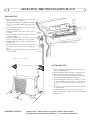
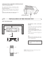
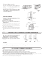
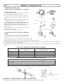
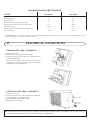
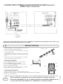
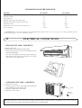
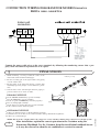
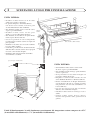
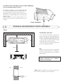
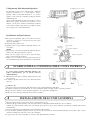
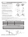
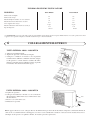
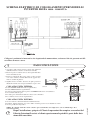
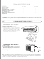
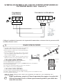
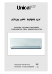
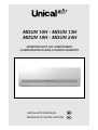
MDUN 10H - MDUN 13H
MDUN 18H - MDUN 24H
INVERTER SPLIT AIR CONDITIONER
CLIMATIZZATORI D’ARIA A PARETE INVERTER
INSTALLATION MANUAL
MANUALE DI INSTALLAZIONE
INSTALLATION
MANUAL
wall type air conditioners inverter
THIS MANUAL IS FOR QUALIFIED STAFF ONLY
FOR THE AIR CONDITIONER TO OPERATE SATISFACTORILY, INSTALL IT
AS OUTLINED IN THIS MANUAL
BE CAREFUL NOT TO SCRATCH THE AIR CONDITIONER UNITS WHEN
HANDLING THEM.
CONNECT THE INDOOR UNIT AND THE OUTDOOR UNIT WITH PROPER
CORDS AND AIR CONDITIONER PIPING
MOVING A SPLIT AIR CONDITIONER TO ANOTHER LOCATION REQUIRES
SPECIAL TECHNIQUE. IF NECESSARY, CONSULT WITH THE SELLER.
INSTALLATION ACCESSORIES
Name and drawing
Quantity
Application
Wall hook bracket for the indoor unit
01
To mount the indoor unit
Power cable
01
Pipette for condensed water drainage
01
For the outdoor unit drainage
Pipe insulation sleeve
01
To insulate the joints of the indoor unit
Remote control
01
1
SELECTING THE INSTALLATION PLACE
Install the indoor unit level on a strong wall
that is not subject to vibrations.
The inlet and outlet ports should not be obstructed: the air should be able to blow all over the
room.
Do not install the unit near a source of heat,
steam, or flammable gas..
Install the unit near an electric socket or private circuit.
Do not install the unit where it will be exposed
to direct sunlight.
Install the unit where connection between
indoor and outdoor unit is as easy as possible.
Install the unit where it is easy to drain the condensed water.
Check the machine operation regularly and
leave the necessary spaces as shown in the picture.
Install the indoor unit where the filter can be
easily accessible.
40
INDOOR UNIT
70
50
insulating
covering
condensed water drain pipe
sleeve
electrical
connections
minimum spaces to be left (mm)
OUTDOOR UNIT
200
60
0
10
0
100
Do not install the outdoor unit near sources of heat,
steam or flammable gases.
Do not install the unit in too windy or dusty places.
Do not install the unit where people often pass.
Select a place where the air discharge and operating
sound level will not disturb the neighbours.
Avoid installing the unit where it will be exposed
to direct sunlight (otherwise use a protection, if
necessary, that should not interfere with the air
flow).
Leave the spaces as shown in the picture for the air
to circulate freely.
Install the outdoor unit in a safe and solid place.
If the outdoor unit is subject to vibration, fix rubber
gaskets onto it.
600
WORKING LIMITS:
cooling mode - unit operatives up to 45° outdoor temperature
heating mode - unit operatives down to - 7°C outdoor temperature
OUTDOOR UNIT CONDENSED WATER DRAINAGE
(only for heat pump models)
The condensed water and the ice formed in the outdoor
unit during heating operation can be drained away
through the drain pipette.
Installation: fasten the drain pipette in the 25 mm hole
placed in the lower part of the unit as shown in the picture.
Connect the condensed water hose and the pipette. Pay
attention that water is drained in a suitable place.
OUTDOOR UNIT
2
INSTALLATION OF THE INDOOR UNIT
WALL HOOK BRACKET
150
Installation of the wall hook
bracket
150
150
1. By using a level, put the wall hook
bracket in a perfect square position, both
vertically and horizontally
2. Fix the bracket first with 5 screws.
3. Use several more tapping screws to secure
the bracket onto the wall with even pressure on
the screws.
4. Cut a hole in the wall for the piping and
electric connection.
2500 mm
Wall
Space
to the
wall
150 m m
above
Mark on the middle of it
Left
Φ55mm or Φ70mm
(Rear piping hole)
indoor
Gradienter
Wall
Space
to the
wall
150mm
above
Right
.
Φ55mm or Φ70mm
(Rear piping hole)
N.B.
Drill a hole in the wall with the outdoor side
5-10 mm lower than the inner side, in order
to have a good drain flow.
Note: The shape and dimensions of the wall
hook bracket could be modified without
prior notice.
outdoor
NOTE : Maintain the drain pipe in the lower part of the
wall hole, or leakage may occur.
5 mm
Refrigerant piping connection
The piping can be run in the 3 directions indicated by
numbers 1, 2, 3 in the figure. When the piping is run in
direction 1 or 3, cut a notch along the groove on the
side of the indoor unit with a cutter.
Run the piping in the direction of the wall hole and bind
the copper pipes, the drain pipe and the power cables
together with the tape with the drain pipe at the bottom,
so that water can flow freely.
The piping run towards the right
1
3
2
wall hook
bracket
Indoor unit installation
1. Run the bound pipe and cables through the wall hole
and mount the indoor unit onto the upper part of the
wall hook bracket securely
2. Arrange the pipes and cables well.
3. Push the lower part of the indoor unit tight against the
wall hook bracket.
NOTE:
Do not bend or crush the indoor unit piping. Avoid
sharp bends with radius of curvature of less than 10 cm.
Do not bend the same part of the pipe too often, after
three times it could be throttled.
Do not remove the flare nut from the indoor unit piping
until immediately before connecting the connection
pipe.
3
refrigerant
pipe
insulation sleeve
power
cable
insulation pipes
signal
cable
refrigerant pipe
condensed water drain pipe
INDOOR UNIT CONDENSED WATER DRAINAGE
The indoor unit condensed water drainage is
fundamental for the success of the installation.
1. Install the drain hose at the bottom of the wall hole.
2. The insulator of the copper pipes should be at least 6
mm thick.
YES
4
NO
NO
Check that:
The top and bottom hooks of the indoor unit are hooked firmly on the wall hook bracket.
The unit is positioned horizontally. If the unit is not installed properly, water will drip onto the floor.
The drain hose has the correct gradient (at least 3 cm for every meter in length).
The drain hose remains at the bottom of the wall hole.
OUTDOOR UNIT INSTALLATION
The outdoor unit should be installed on a solid wall and fastened securely
The following procedure must be observed before connecting the pipes and electric cables:
decide which is the best position on the wall and leave enough space to be able to carry out maintenance easily.
Fasten the support to the wall using screw anchors which are particularly suited to the type of wall;
Use a larger quantity of screw anchors than normally required for the weight they have to bear: during operation the machine
vibrates and has to remain fastened in the same position for years without the screws becoming loose.
The unit must be installed following the national regulations
5
PIPING CONNECTION
ATTENTION: ONLY ACR
copper pipes for air conditioners are allowed
Do not remove the cap from the pipe until connecting
it, to avoid dampness or dirt from entering.
If the pipe is bent or pulled too often, it will become
stiff. Do not bend the pipe more than three times at one
place.
When extending the rolled pipe, straighten the pipe by
unwinding it gently as shown in the figure below
NO
YES
connection pipes
Connecting the pipes
flare nuts
CONNECTIONS TO THE INDOOR UNIT
Shape the connection pipe following the diagram.
Remove the indoor unit pipe cap (check that there is no
debris inside).
Insert the flare nut and create a flange at the extreme
end of the connection pipe.
Connect the pipes by using two wrenches.
liquid tap
gas tap
indoor unit
CONNECTIONS TO THE OUTDOOR
UNIT
Screw the flare nuts to the outdoor unit coupling with
the same tightening procedures described for the indoor
unit.
To avoid leakage, pay particular attention to the following points:
Tighten the flare nuts using two wrenches. Pay attention not to damage the pipes.
If the tightening torque is not sufficient, there will probably be some leakage. With excessive tightening torque there will also be
some leakage, as the flange could be damaged.
The surest system consists in tightening the connection by using a fix wrench and a torque wrench: in this case use the following
table.
FLANGE CONNECTION TIGHTENING TORQUE
Pipe
Tightening torque
[N x m]
Corresponding stress
(using a 20 cm wrench)
6,35 mm (1/4”)
15 - 20
wrist strength
9,52 mm (3/8”)
31 - 35
arm strength
(1/2”)
50 - 55
arm strength
15,88 mm (5/8”)
65 - 70
arm strength
12,70 mm
TIGHTENING TORQUE FOR PROTECTION CAPS
Tightening torque
[N x m]
Service port nut
7-9
Protection caps
25 - 30
To empty the refrigerant pipe from air and humidity, the use of the vacuum pump is recommended.
torque wrench
Service port nut
IMPORTANT ! REFRIGERANT LEAKAGE INSPECTION
After connecting the piping, check the joints for refrigerant leakage with leak detector carefully.
INFORMATION FOR THE INSTALLER
MODEL
10000 BTU/h
13000 BTU/h
Liquid pipe diameter
1/4”
1/4”
Gas pipe diameter
3/8”
3/8”
Maximum lenght of pipe with standard charge
5m
5m
Maximum distance between indoor and outdoor unit
Additional gas charge
Maximum difference in level between indoor and outdoor unit (1)
Type of refrigerant
15 m
20 m
15
m
20 g/m
20 g/m
10 m
10 m
R410A
R410A
(1) ATTENTION: In case the outdoor unit has been installed higher than the indoor unit, it is necessary to provide “S” oil traps (or liquid separator)
to both refrigerant pipes, overy 3 m of difference in level.
6
ELECTRICAL CONNECTIONS
INDOOR UNIT 10000 - 13000 BTU/h
1. Lift the front panel.
2. Take off the cover as indicated in the figure.
3. Connect the cable wires to the screw terminals by following the numbering.
Use wire size suitable to the electric power input (see
name plate on the unit) and according to all current
national safety code requirements.
OUTDOOR UNIT 10000 - 13000 BTU/h
1. Take the cover away.
2. Connect the cable wires to the terminal board using the
same numbering as in the indoor unit.
3. Fasten the cables with a cable-clamp.
4. Replace the covers again.
screw
Remove
the cover
N.B.: The unit must be connected to the power supply system through an onnipolar switch (3 mm distance). In case the power supply cable is damaged, it must be replaced by the manufacturer or qualified staff.
CONNECTION WIRING DIAGRAM FOR MODELS inverter
R410A 10000 - 13000 BTU/h
Connect the power cable wires to the screw terminals by following the numbering; ensure that a properly sized and connected ground wire is in a place.
7
FINAL STAGES
1. Wind insulating covering around the joints of the
indoor unit and fix it with insulating tape.
2. Fix the exceeding part of the signal cable to the piping
or to the outdoor unit.
3. Fix the piping to the wall (after having coated it with
insulating tape) using clamps or insert them into plastic
slots.
4. Seal the hole in the wall through which he piping is
passed so that no air or water can filter.
insulating covering
insulating tape
piping
clamps
1. INDOOR UNIT TEST
Do the ON/OFF and FAN keys operate normally?
Does the MODE key operate normally?
Do the set point and TIMER keys function properly?
Does each lamp light normally?
Do the louvers for air flow direction operate normally?
Is the condensed water drained regular?
gasket
piping
(indoor)
(outdoor)
OUTDOOR UNIT TEST
Is there any abnormal noise or vibration during operation?
Could the noise, the air flow or the condensed water drainage disturb the neighbours?
Is there any coolant leakage?
wall
NOTE: The electronic controller allows the compressor to start only three minutes after voltage has reached the system.
!
After installation, explain the correct operation to the Customer using the
Instruction Handbook. Let the Customer keep this installation handbook because it may be referred to when the air conditioner is serviced or moved.
cod. 000649B
INFORMATION FOR THE INSTALLER
MODEL
18000 BTU/h
24000 BTU/h
Liquid pipe diameter
1/4”
1/4”
Gas pipe diameter
1/2”
5/8”
Maximum lenght of pipe with standard charge
5m
5m
Maximum distance between indoor and outdoor unit
Additional gas charge
Maximum difference in level between indoor and outdoor unit (1)
Type of refrigerant
25 m
25 m
m
25
20 g/m
20
50 g/m
g/m
10 m
10 m
R410A
R410A
(1) ATTENTION: In case the outdoor unit has been installed higher than the indoor unit, it is necessary to provide “S” oil traps (or liquid separator)
to both refrigerant pipes, overy 2 m of difference in level.
6
ELECTRICAL CONNECTIONS
INDOOR UNIT 18000 - 24000 BTU/h
1. Lift the front panel.
2. Take off the cover as indicated in the figure.
3. Connect the cable wires to the screw terminals by following the numbering.
Use wire size suitable to the electric power input (see
name plate on the unit) and according to all current
national safety code requirements.
OUTDOOR UNIT 18000 - 24000 BTU/h
1. Take the cover away.
2. Connect the cable wires to the terminal board using the
same numbering as in the indoor unit.
3. Fasten the cables with a cable-clamp.
4. Replace the covers again.
screw
Remove
the cover
N.B.: The unit must be connected to the power supply system through an onnipolar switch (3 mm distance). In case the power supply cable is damaged, it must be replaced by the manufacturer or qualified staff.
ǃ
CONNECTION WIRING DIAGRAM FOR MODELS inverter
R410A 18000 - 24000 BTU/h
Indoor unit
connection
N(1) 2
3
L
N
Connect the power cable wires to the screw terminals by following the numbering; ensure that a properly sized and connected ground wire is in a place.
7
FINAL STAGES
1. Wind insulating covering around the joints of the
indoor unit and fix it with insulating tape.
2. Fix the exceeding part of the signal cable to the piping
or to the outdoor unit.
3. Fix the piping to the wall (after having coated it with
insulating tape) using clamps or insert them into plastic
slots.
4. Seal the hole in the wall through which he piping is
passed so that no air or water can filter.
insulating covering
insulating tape
piping
clamps
1. INDOOR UNIT TEST
Do the ON/OFF and FAN keys operate normally?
Does the MODE key operate normally?
Do the set point and TIMER keys function properly?
Does each lamp light normally?
Do the louvers for air flow direction operate normally?
Is the condensed water drained regular?
gasket
piping
(indoor)
(outdoor)
OUTDOOR UNIT TEST
Is there any abnormal noise or vibration during operation?
Could the noise, the air flow or the condensed water drainage disturb the neighbours?
Is there any coolant leakage?
wall
NOTE: The electronic controller allows the compressor to start only three minutes after voltage has reached the system.
!
After installation, explain the correct operation to the Customer using the
Instruction Handbook. Let the Customer keep this installation handbook because it may be referred to when the air conditioner is serviced or moved.
cod. 000649B
MANUALE
INSTALLAZIONE
climatizzatori d’aria a parete inverter
QUESTO MANUALE È DESTINATO A PERSONALE QUALIFICATO
PER UN CORRETTO FUNZIONAMENTO, IL CLIMATIZZATORE DEVE ESSERE
INSTALLATO COME DESCRITTO IN QUESTO MANUALE.
FARE ATTENZIONE A NON GRAFFIARE LE UNITÀ MANEGGIANDOLE.
COLLEGARE L’UNITÀ INTERNA E L’UNITÀ ESTERNA UTILIZZANDO
SOLO I CAVI ELETTRICI E LE TUBAZIONI DEL TIPO ADATTO.
RIMUOVERE UN CLIMATIZZATORE SPLIT DOPO CHE E’ STATO INSTALLATO
E’ UN’OPERAZIONE CHE RICHIEDE UNA SPECIFICA PREPARAZIONE: NEL
CASO SIA NECESSARIO, CONSULTARE IL VOSTRO RIVENDITORE.
ACCESSORI PER L’INSTALLAZIONE
Nome e disegno
Quantità
Applicazione
Dima per l’unità interna
01
Per installare l’unità interna
Cavo alimentazione
01
Pipetta per scarico condensa
01
Per lo scarico dell’unità esterna
Guaina isolante per tubazioni
01
Per isolare i giunti dell’unità interna
Telecomando
01
1
SCELTA DEL LUOGO PER L’INSTALLAZIONE
·
·
·
·
·
·
·
·
·
Installare l’unità interna su di un muro
solido, non soggetto a vibrazioni.
Le aperture di ripresa e di mandata dell’aria
non devono essere ostruite; l’aria deve poter
circolare liberamente in tutto l’ambiente.
Non installare l’unità vicino a fonti di calore,
vapore o gas infiammabili.
Installare l’unità vicino ad una presa
elettrica o con un collegamento dedicato.
Non installare la macchina in un punto diretta
mente esposto alla luce del sole.
Cercare la posizione in cui il collegamento
tra unità interna ed unità esterna sia il più sem
plice possibile.
Installare la macchina dove sia facile realizzare
lo scarico della condensa.
Controllare periodicamente il funzionamento
della macchina e lasciare attorno ad essa gli spazi
necessari, come mostrato in figura.
Installare l’unità interna in modo che il filtro
sia facilmente accessibile.
40
UNITA’ INTERNA
70
50
isolante
termico
tubo di scarico della condensa
manicotto
collegamenti
elettrici
spazi di rispetto minimi (mm)
UNITA’ ESTERNA
200
·
·
·
·
·
·
60
0
10
0
100
600
·
·
Non installare l’unità esterna vicino a fonti
di calore, vapore o gas infiammabili.
Non installare l’unità in luogo particolarmente
ventoso o polveroso.
Non posizionare la macchina in luoghi con
passaggio continuo di persone.
Rispettare i vicini facendo in modo che non
siano disturbati dal rumore o dal flusso dell’aria.
Evitare l’installazione in luoghi direttamente
esposti alla luce del sole (se costretti, prevedere
una protezione che non vada ad interferire con
l’uscita dell’aria).
Lasciare gli spazi necessari alla circolazione
dell’aria, come evidenziato in figura.
Installare l’unità esterna in un luogo sicuro e
stabile.
Qualora l’unità esterna dovesse vibrare,
fissarla interponendo delle guarnizioni di
gomma.
Limiti di funzionamento: le unità funzionano correttamente alle temperature esterne comprese tra 45°C
(in modalità raffreddamento) e -7°C (in modalità riscaldamento).
SCARICO della CONDENSA DALL’UNITÀ ESTERNA
(solo nei modelli pompa di calore)
La condensa e il ghiaccio, che si formano nell’unità
esterna durante il funzionamento in riscaldamento, possono essere eliminate attraverso la pipetta di scarico.
Installazione: fissare la pipetta di scarico nel foro da 25
mm che si trova sul fondo dell’unità, come mostrato nel
disegno a fianco.
Collegare il tubo per lo scarico della condensa con la
pipetta e fare in modo che l’acqua finisca in uno scarico adatto.
UNITA’ ESTERNA
2
INSTALLAZIONE DELL’UNITÀ INTERNA
DIMA
150
Installazione della dima
150
150
1. Con l’aiuto di una livella, posizionare la
dima in modo tale che risulti perfettamente in
asse,sia verticalmente che orizzontalmente.
2. Fissare la dima inizialmente con 5 viti.
3. Usare poi altre viti per fissare la dima al muro
in modo uniforme su tutta la superficie.
4. Forare il muro per il passaggio delle tubazioni e dei collegamenti elettrici.
2500 mm
Wall
Space
to the
wall
150 m m
above
Mark on the middle of it
Left
Φ55mm or Φ70mm
(Rear piping hole)
interno
Gradienter
Wall
Space
to the
wall
150mm
above
Right
.
Φ55mm or Φ70mm
(Rear piping hole)
N.B.
Praticare un foro nel muro che sia, dalla parte
esterna di 5-10 mm più basso che all’interno
in modo che la pendenza favorisca il deflusso
della condensa.
LA FORMA DELLA DIMA POTREBBE
ESSER DIVERSA DA QUELLA
MOSTRATA IN FIGURA
esterno
NOTE : Mantenere il tubo di scarico nella parte bassa del
foro nel muro o potrebbero esserci delle perdite.
5 mm
Collegamento delle tubazioni frigorifere
Le tubazioni possono essere orientate nelle 3 direzioni
indicate dai numeri 1, 2, 3 nella figura a fianco.
Quando i tubi escono nelle direzioni 1 o 3, si deve
tagliare con un cutter la scanalatura predisposta sul lato
dell’unità interna.
Girare i tubi nella direzione del foro nel muro e unire i
tubi di rame, il tubo di scarico per la condensa e i cavi
elettrici con un nastro isolante, mantenendo il tubo di
scarico della condensa più in basso possibile in modo
che l’acqua possa scorrere liberamente.
Le tubazioni escono a destra.
1
3
2
dima
Installazione dell’unità interna
1. Far passare le tubazioni, unite ai cavi, attraverso il foro
nel muro e agganciare l’unità interna alla parte
superiore della dima.
2. Sagomare bene i tubi e i cavi.
3. Spingere bene la parte inferiore dell’unità interna contro la dima.
NOTE:
Non piegare o strozzare le tubazioni dell’unità interna.
Evitare curve di raggio inferiore ai 10 cm.
Non curvare troppe volte lo stesso tratto di tubo:
dopo 3 volte rischia di strozzarsi.
Rimuovere la chiusura dei tubi dell’unità interna
solo immediatamente prima di effettuare i collegamenti.
tubazione
frigorifera
cavo di
potenza
guaina isolante
isolamento tubazioni
cavo dei
segnali
tubazione frigorifera
tubo di scarico per la condensa
3
SCARICO DELLA CONDENSA DELL’UNITÀ INTERNA
Lo scarico della condensa dell’unità interna è un
punto fondamentale per la buona riuscita
dell’installazione.
1. Mantenere il tubo per la condensa sulla parte bassa del
foro nel muro.
2. L’isolante dei tubi in rame deve avere almeno 6 mm di
spessore.
4
SI
NO
NO
Verificare che:
Gli agganci superiori ed inferiori dell’unità interna siano inseriti saldamente sulla dima.
L’unità sia posizionata orizzontalmente. Se non é installata in bolla, potrebbe perdere acqua sul pavimento.
Il tubo di scarico abbia la corretta pendenza (minimo 3 cm ogni metro di lunghezza).
Il tubo di scarico rimanga sulla parte bassa del foro nel muro.
INSTALLAZIONE DELL’UNITÀ ESTERNA
Montare l’unità esterna su una parete solida e in modo molto sicuro.
Attenersi alla procedura descritta e solo in seguito iniziare i collegamenti delle tubazioni e dei cavi elettrici:
stabilire la posizione idonea sulla parete, prevedendo gli spazi necessari per poter effettuare agevolmente eventuali interventi di
manutenzione;
fissare la staffa alla parete utilizzando dei tasselli adatti al tipo di muro;
Usare tasselli in quantità maggiore in base al peso che devono sostenere: durante il funzionamento la macchina vibra e dovrà
rimanere installata per anni senza che le viti si allentino.
L’apparecchio deve essere installato secondo le regole impiantistiche nazionali
5
COLLEGAMENTO DELLE TUBAZIONI
ATTENZIONE: utilizzare SOLAMENTE
tubi di rame per condizionatori di tipo ACR
Come collegare i tubi
Rimuovere la chiusura dei tubi solo al momento di
effettuare il collegamento: si deve assolutamente evitare che entri umidità o sporcizia.
Se un tubo viene curvato troppe volte, diventa duro:
non curvarlo più di 3 volte nello stesso tratto.
Svolgere il tubo srotolandolo senza tirare, come
mostrato in figura.
CONNESSIONI ALL’UNITÀ INTERNA
Avvitare i bocchettoni agli attacchi dell’unità esterna
con lo stesso serraggio descritto per l’unità interna.
tubi di collegamento
bocchettoni
rubinetto del liquido
Sagomare i tubi di collegamento secondo il tracciato.
Togliere la calottina di chiusura dei tubi dell’unità
interna (verificare che all’interno non siano rimaste
impurità).
Inserire il bocchettone e praticare la flangia all’estremità del tubo di collegamento.
Collegare i tubi usando due chiavi.
CONNESSIONI ALL’UNITA’ ESTERNA
NO
SI
rubinetto del gas
unità interna
valvola
del liquido
valvola del gas
rubinetto
tappi di
protezione
attacco
di servizio
rubinetto
Per evitare perdite porre particolare attenzione ai seguenti punti:
Stringere i bocchettoni usando due chiavi e facendo attenzione a non danneggiare i tubi.
Se la forza di serraggio è insufficiente, vi saranno probabilmente delle perdite. Anche se la forza è eccessiva potranno esserci
delle perdite poiché è facile danneggiare la flangia.
Il sistema più sicuro consiste nel serrare la connessione utilizzando una chiave fissa e una chiave dinamometrica: in questo caso
utilizzare la seguente tabella.
COPPIE DI SERRAGGIO PER LE CONNESSIONI A FLANGIA
Tubo
Coppia di serraggio
[N x m]
Sforzo corrispondente
(usando una chiave di 20 cm)
6,35 mm (1/4”)
15 - 20
forza del polso
9,52 mm (3/8”)
31 - 35
forza del braccio
12,70 mm (1/2”)
50 - 55
forza del braccio
15,88 mm (5/8”)
65 - 70
forza del braccio
COPPIE DI SERRAGGIO PER TAPPI DI PROTEZIONE
Coppia di serraggio
[N x m]
Attacco di servizio
7-9
Tappi di protezione
25 - 30
Si consiglia di utilizzare la centralina del vuoto per effettuare lo spurgo della linea frigorifera da aria ed umidità.
chiave dinamometrica
attacco di servizio
IMPORTANTE ! CONTROLLO FUGHE DI REFRIGERANTE
Dopo aver eseguito le connessioni controllarle sempre con un cerca fughe.
INFORMAZIONI PER L’INSTALLATORE
10000 BTU/h
13000 BTU/h
Diametro tubo del liquido
1/4”
1/4”
Diametro tubo del gas
3/8”
3/8”
MODELLO
Massima lunghezza del tubo con carica standard
5m
5m
Massima distanza tra unità interna ed esterna
15 m
20 m
m
15
20 g/m
20 g/m
10 m
10 m
Carica supplementare del gas
Massimo dislivello tra unità interna ed esterna (1)
Tipo di refrigerante
R410A
R410A
(1) ATTENZIONE: nel caso in cui l’unità esterna sia stata installata ad un’altezza superiore rispetto all’unità interna é necessario praticare dei sifoni
o applicare dei separatori di liquido su entrambe le tubazioni ogni 3 metri di dislivello.
6
COLLEGAMENTI ELETTRICI
UNITÀ INTERNA 10000 - 13000 BTU/h
1. Sollevare il pannello frontale.
2. Togliere il coperchio come indicato in figura.
3. Collegare i conduttori ai morsetti a vite rispettando
la numerazione: utilizzare conduttori di sezione adeguata alla potenza e corrente elettrica assorbita dal climatizzatore (vedi dati di targa sull’unità esterna) seguendo
le normative di sicurezza nazionali in vigore.
UNITÀ ESTERNA 10000 - 13000 BTU/h
1. Togliere il coperchio.
2. Collegare attentamente i fili del cavo di connessione
alla morsettiera utilizzando la stessa numerazione usata
all’unità interna.
3. Fissare i cavi con il ferma-cavi.
4. Rimettere il coperchio.
vite
sfilare
coperchio
N.B. L’apparecchio deve essere collegato alla rete di alimentazione per mezzo di un’interruttore onnipolare con distanza minima di
3 mm. Se il cavo di alimentazione è danneggiato, esso deve essere sostituito dal costruttore o dal suo servizio di assistenza tecnica o
comunque da una persona con qualifica similare, in modo da prevenire ogni rischio.
SCHEMA ELETTRICO DI COLLEGAMENTO PER MODELLI
INVERTER R410A 10000 - 13000 BTU/h
Collegare i conduttori ai morsetti a vite rispettando la numerazione; assicurarsi che sia presente un’efficace linea di messa a terra.
7
FASI CONCLUSIVE
1. Avvolgere dell’ isolante termico attorno alle giunzioni
dell’unità interna e fissarlo con del nastro isolante.
2. Fissare la parte eccedente del cavo dei segnali alle tubazioni o all’unità esterna.
3. Fissare le tubazioni alla parete (dopo averle rivestite
con nastro isolante) usando delle fascette oppure inserirle in canaline di plastica.
4. Sigillare il foro nel muro attraverso il quale passano le
tubazioni in modo che non possano filtrare acqua o aria.
1. COLLAUDO UNITA’ INTERNA
isolante termico
nastro isolante
fascette
tubazioni
tubazioni
I tasti ON/OFF e FAN funzionano regolarmente?
Il tasto MODE funziona regolarmente?
I tasti per l’impostazione del set point e del TIMER funzionano correttamente?
Si accendono tutte le spie?
Le alette per l’orientamento dell’aria emessa sono efficienti?
La condensa viene scaricata regolarmente?
guarnizione
(interno)
(esterno)
muro
Vi sono rumori o vibrazioni durante il funzionamento?
Il rumore, il flusso dell’aria o lo scarico della condensa possono recare disturbo ai vicini?
Vi sono perdite di refrigerante?
NOTA: Il controllo elettronico dà il consenso per l’avviamento del compressore solo tre minuti dopo che è
stata data tensione.
!
Dopo l’installazione, spiegate al Cliente le operazioni da compiere servendovi del
Libretto Istruzioni.Lasciate al cliente questo manuale poichè fa parte della dotazione della macchina.
cod. 000649B
COLLAUDO UNITA’ ESTERNA
INFORMAZIONI PER L’INSTALLATORE
18000 BTU/h
MODELLO
24000 BTU/h
Diametro tubo del liquido
1/4”
1/4”
Diametro tubo del gas
1/2”
5/8"
1/2”
Massima lunghezza del tubo con carica standard
5m
5m
Massima distanza tra unità interna ed esterna
25
30 m
m
30 m
m
25
Carica supplementare del gas
50
20 g/m
g/m
50 g/m
5m
5m
Massimo dislivello tra unità interna ed esterna (1)
Tipo di refrigerante
R410A
R410A
(1) ATTENZIONE: nel caso in cui l’unità esterna sia stata installata ad un’altezza superiore rispetto all’unità interna é necessario praticare dei sifoni
o applicare dei separatori di liquido su entrambe le tubazioni ogni 2 metri di dislivello.
6
COLLEGAMENTI ELETTRICI
UNITÀ INTERNA 18000 - 24000 BTU/h
1. Sollevare il pannello frontale.
2. Togliere il coperchio come indicato in figura.
3. Collegare i conduttori ai morsetti a vite rispettando
la numerazione: utilizzare conduttori di sezione adeguata alla potenza e corrente elettrica assorbita dal climatizzatore (vedi dati di targa sull’unità esterna) seguendo
le normative di sicurezza nazionali in vigore.
UNITÀ ESTERNA 18000 - 24000 BTU/h
1. Togliere il coperchio.
2. Collegare attentamente i fili del cavo di connessione
alla morsettiera utilizzando la stessa numerazione usata
all’unità interna.
3. Fissare i cavi con il ferma-cavi.
4. Rimettere il coperchio.
vite
sfilare
coperchio
N.B. L’apparecchio deve essere collegato alla rete di alimentazione per mezzo di un’interruttore onnipolare con distanza minima di
3 mm. Se il cavo di alimentazione è danneggiato, esso deve essere sostituito dal costruttore o dal suo servizio di assistenza tecnica o
comunque da una persona con qualifica similare, in modo da prevenire ogni rischio.
SCHEMA ELETTRICO DI COLLEGAMENTO PER MODELLI
INVERTER R410A 18000 - 24000 BTU/h
Connessioni
unità interna
Connessioni unità esterna
N(1) 2
3
L
N
Collegare i conduttori ai morsetti a vite rispettando la numerazione; assicurarsi che sia presente un’efficace linea di messa a terra.
7
FASI CONCLUSIVE
1. Avvolgere dell’ isolante termico attorno alle giunzioni
dell’unità interna e fissarlo con del nastro isolante.
2. Fissare la parte eccedente del cavo dei segnali alle tubazioni o all’unità esterna.
3. Fissare le tubazioni alla parete (dopo averle rivestite
con nastro isolante) usando delle fascette oppure inserirle in canaline di plastica.
4. Sigillare il foro nel muro attraverso il quale passano le
tubazioni in modo che non possano filtrare acqua o aria.
1. COLLAUDO UNITA’ INTERNA
isolante termico
nastro isolante
fascette
tubazioni
tubazioni
I tasti ON/OFF e FAN funzionano regolarmente?
Il tasto MODE funziona regolarmente?
I tasti per l’impostazione del set point e del TIMER funzionano correttamente?
Si accendono tutte le spie?
Le alette per l’orientamento dell’aria emessa sono efficienti?
La condensa viene scaricata regolarmente?
guarnizione
(interno)
(esterno)
muro
Vi sono rumori o vibrazioni durante il funzionamento?
Il rumore, il flusso dell’aria o lo scarico della condensa possono recare disturbo ai vicini?
Vi sono perdite di refrigerante?
NOTA: Il controllo elettronico dà il consenso per l’avviamento del compressore solo tre minuti dopo che è
stata data tensione.
!
Dopo l’installazione, spiegate al Cliente le operazioni da compiere servendovi del
Libretto Istruzioni.Lasciate al cliente questo manuale poichè fa parte della dotazione della macchina.
cod. 000649B
COLLAUDO UNITA’ ESTERNA
La Unical declina ogni responsabilità per le possibili inesattezze se dovute ad errori di trascrizione o di stampa. Si riserva altresì il diritto
di apportare ai propri prodotti quelle modifiche che riterrà necessarie o utili, senza pregiudicarne le caratteristiche e s s e n z i a l i .