1
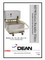
"U" & "AU" CONFIGURATIONS
MF90 Series Portable Filters
Installation & Operation Manual
MF90-65, -80, -110, -126, -160 & -172
Dean Industries, a member of the Commercial Food Equipment Service Association,
recommends using CFESA Certified Technicians.
24-Hour Service Hotline 1-800-551-8633
Price: $6.00
819-5808
10-00
Please read all sections of this manual and retain for future reference.
Installation, maintenance, and repairs should be performed by your Dean
Factory Authorized Service Center.
CAUTION
DO NOT STORE OR USE GASOLINE OR OTHER FLAMMABLE VAPORS AND LIQUIDS IN
THE VICINITY OF THIS OR ANY OTHER COOKING APPLIANCE.
WARNING
IMPROPER INSTALLATION, ADJUSTMENT, ALTERATION, SERVICE, OR
MAINTENANCE CAN CAUSE PROPERTY DAMAGE, INJURY OR DEATH. READ THE
INSTALLATION, OPERATING AND MAINTENANCE INSTRUCTIONS THROUGHLY
BEFORE INSTALLING OR SERVICING THIS EQUIPMENT.
WARNING
SAFE AND SATISFACTORY OPERATION OF YOUR EQUIPMENT DEPENDS ON ITS
PROPER INSTALLATION. INSTALLATION MUST CONFORM TO LOCAL CODES, OR IN
THE ABSENCE OF LOCAL CODES, WITH THE LATEST EDITION OF THE NATIONAL
ELECTRIC CODE, N.F.P.A. 70.
i
MF90 Series Portable Filters
TABLE OF CONTENTS
Page #
1.
INTRODUCTION
1-1
2.
IMPORTANT INFORMATION
2-1
3.
INSTALLATION INSTRUCTIONS
3-1
4.
FILTER OPERATION
4-1
5.
CLEANING AND MAINTENANCE
5-1
6.
TROUBLESHOOTING
6-1
7.
PARTS LIST
7-1
ii
DEAN PORTABLE MICRO-FLO OIL FILTRATION SYSTEMS
CHAPTER 1: INTRODUCTION
1.1 Ordering Parts
Customers may order parts directly from their local Factory Authorized Service Center (FASC). See
the numbers listed in section 1.2 for information of your nearest FASC.
To speed up your order, the following information is required:
Model Number
Serial Number
Type
With/Without
Heater
Optional Features
Item Part Number
Quantity Needed
1.2 Service Information
Call the 1-800-551-8633 or (318) 865-1711 Service Hotline number for the location of your nearest
Factory Authorized Service Center. Always give the model and serial numbers of your filter unit.
Also, identify if your unit is supplied with or without a heater.
To assist you more efficie ntly, the following information will be needed:
Model Number
Serial Number
With/Without
Heater
Optional Features
Type
Nature of Problem:
Additional information (i.e. oil temperature at filter time, time of day and other pertinent
information) may be helpful in solving your service problem. Communicate with your service
technician.
1-1
1.3 After Purchase
In order to improve service, have the following chart filled in by the Dean Authorized Service
Technician who installed this equipment.
Authorized Service
Technician/FASC
Address
Telephone/Fax
Model Number
Serial Number
1.4 Safety Information
Before attempting to operate your unit, read the instructions in this manual thoroughly.
Throughout this manual, you will find notations enclosed in double-bordered boxes similar to the
ones below.
CAUTION boxes contain information about actions or conditions that may cause or result in a
malfunction of your system.
CAUTION
Example of a CAUTION box.
WARNING boxes contain informa tion about actions or conditions that may cause or result in
damage to your system, and which may cause your system to malfunction.
WARNING
Example of a WARNING box.
DANGER boxes contain information about actions or conditions that may cause or result in injury
to personnel, and which may cause damage to your system and/or cause your system to malfunction.
DANGER
Example of a DANGER box.
1-2
DEAN PORTABLE MICRO-FLO OIL FILTRATION SYSTEMS
CHAPTER 2: IMPORTANT INFORMATION
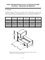
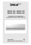
2.1 General
The MF-90 portable oil filters may be used with a variety of Dean fryers, as well as other
manufacturers’ equipment. Oil capacity ranges from 65 to 172 pounds of oil, depending on the
model. Length, width, height and tank depth dimensions for all units are listed in the table below.
Model
MF-90/65
MF-90/80
MF-90/80 LP
MF-90/110
MF-90/160
MF-90/172
Unit Height
(inches)
26.87
24.12
24
26.37
25.25
31
Tank Width
(inches)
14
18.25
18
18.25
18.25
18
Tank Length
(inches)
29.5
24.75
34.75
24.75
37
29
Tank Height
(inches)
14
11.25
9.63
13.25
11.5
15
Oil Capacity
(pounds)
65
80
105
110
160
172
Unit Height
Tank Height
Tank Width
Tank Length
MF90 Series filter unit dimensions (unit and tank heights are measured from bottom
of casters to top of unit and tank, respectively).
2-1
2.1 General (cont.)
The used oil may be drained by gravity from the fryer into the filter pan, or removed from the fryer
by use of a suction/return hose, according to model. The oil is pumped back into the fryer vessel
using the same suction/return hose.
Oil or shortening is filtered through replaceable filter paper. Filter powder, which enhances the
filtering process, is distributed over the paper prior to filtering.
All units are shipped completely assembled with accessories packed inside the frypots. All units are
adjusted, tested and inspected at the factory before shipment.
CAUTION
The on-site supervisor is responsible for ensuring that operators are made aware of
the inherent dangers of operating a hot oil filter system, particularly the aspects of
oil filtration, and drain ing/cleaning procedures.
A 7-amp (115V-domestic), or 5-amp (230V- international) circuit breaker installed on the filter unit
switches the power OFF if an overload occurs.
NOTE: If the circuit breaker is triggered, depress the reset button to activate the circuit after the
failure has been detected and repaired.
2.2 Rating Plate
Information on the rating plate includes model and serial numbers, as well as electrical requirements.
Have the rating plate information handy when communicating with the factory about a unit or
requesting special parts or information. Without this information, proper identification of the unit
cannot be confirmed.
2.3 Pre-Installation
NOTE: Failure to use qualified service personnel will void the Dean warranty.
A. Standards: Use of this filter unit must be in accordance with all applicable state and local
codes.
B. Electrical Connections: Domestic MF90 filter units require a 115V 60 Hz., 15 amp electrical
supply. Units are equipped with a grounded male receptacle for use with a flexible six- foot,
16-3 SJT power cord set. If an extension cord is required, it must be a three-conductor,
grounded power cord of at least 16 gauge.
2-2
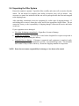
2.4 Unpacking the Filter System
Ensure the container is upright. Unpack the filter carefully and remove all accessories from the
carton. Do not discard or misplace parts and/or accessories; they will be needed. Any
accessories or starter kits included with the unit will be packaged inside the filter tank strapped
to the shipping frame.
After unpacking, immediately check the equipment for visible signs of shipping damage. If
such damage has occurred, contact the carrier and file the appropriate freight claims. Do not
contact the factory, as the responsibility of shipping damage is between the carrier and dealer
or end- user.
If your equipment arrives damaged:
a. File claim for damages immediately – Regardless of extent of damage.
b. Visible loss or damage – Be sure this is noted on the freight bill or express receipt and is
signed by the person making the delivery.
c. Concealed loss or damage – If damage is unnoticed until equipment is unpacked, notify
freight company or carrier immediately, and file a concealed damage claim. This should be
done within 15 days of date of delivery. Retain the shipping container for inspection.
NOTE: Dean does not assume responsibility for damage or loss incurred in transit.
2-3
DEAN PORTABLE MICRO-FLO OIL FILTRATION SYSTEMS
CHAPTER 3: INSTALLATION INSTRUCTIONS
3.1 Assembling The Filter System
On initial installation and before each use, remove all loose parts from the filter, wash the
filter pan and all accessories in hot, soapy water and dry thoroughly.
WARNING!
Water or boil-out solution MUST not be allowed to drain into the filter pan or
filter system. Irreversible damage will result if water is allowed into the
system, and the warranty will be voided.
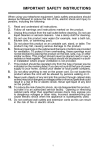
The MF90 filtration system uses a filter support grid, two sheets of filter paper and a holddown ring to secure the filter paper in place.
3.1.1 Filter Paper Configuration
See
illustration
assembly.
for
proper
5
1.
2.
3.
4.
5.
4
3
2
1
Filter Pan Cover
Hold-Down Ring
Filter Paper (2 sheets)
Screen/Support Grid
Filter Pan Assembly
A. First, place the support grid in the bottom of filter pan.
B. Put two filter paper sheets on top of the support grid. Be sure the paper covers the whole
filter pan bottom.
C. Position the hold-down ring on top of the filter papers and latch the hold-down ring and
filter papers securely against the filter pan bottom, forming a tight seal.
3-1
3.1.1 Filter Paper Configuration (cont.)
D. Sprinkle 16 ounces of filter powder on the top filter sheet. Distribute the powder over the
filter paper as evenly as possible. If filtering a second frypot immediately after the first,
add only 8 ounces of filter powder for the second filtering.
E. Place the crumb catcher screen (if used) in the filter pan. Allow the crumb catcher to rest
on the top edges of the hold-down ring.
F. Place filter pan cover onto the filter pan assembly.
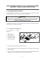
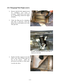
G. Position filter under the fryer drainpipe for gravity drain operations, or nearby for suction
operations. Lock rear casters to prevent filter from moving out of position during the
filtering process.
MF-90 portable filter positioned correctly next to fryer drain valve, with rear casters
locked in place.
3-2
DEAN PORTABLE MICRO-FLO OIL FILTRATION SYSTEMS
CHAPTER 4: FILTER OPERATION
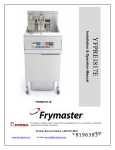
4.1 General
The Dean Portable Filters are designed to operate primarily as an independent filter unit.
Operations always start by ensuring the unit is properly plugged in, then rolling the filter to
the fryer to be filtered. The filter will work directly under the fryers’ drain valves. The
general layout of a generic MF90 Series Portable Filter System with major components
identified is illustrated below.
WAND
OIL-RETURN HOSE
FRY VESSEL
QUICK-DISCONNECT
COUPLING
PUMP
DRAIN VALVE WITH
EXTENSION
FILTER PAN
Arrows indicate direction of oil flow during the filtration process.
4-1
LOCKING
REAR
CASTERS
4.2 Filtering Tools
These tools are not required, but are recommended to make the filtering task easier.
A. Measuring Cup : Used to measure eight ounces by volume of filter powder.
B. Scrub Brush: To clean sediment and residue from the filter pan and fry vessel.
C. Appropriate Clothing.
4.3 Filter Preparation
1.
Position the MF-90 filter next to the fryer. Remove filter pan lid and position filter
unit under frypot drain- valve extension
2.
Ensure the filter power switch is in “OFF” position prior to connecting to power
supply.
3.
Plug power cord into electrical outlet. The filter unit is ready for filtering. If
equipped, turn on heater switch to allow pan to preheat. After filtering, follow
instructions in Section 4.4, Changing Filter Paper.
CAUTION
The crumb tray (if equipped) in portable filter systems must be emptied into a
fireproof container at the end of frying operations each day. Some food
particles can spontaneously combust if left soaking in certain shortening
material.
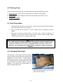
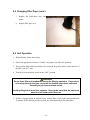
4.4 Changing Filter Paper
The top sheet of filter paper should be replaced
after each filter session, and most certainly at the
beginning of each workday. If filter paper is
replaced once per day, excess sediment should
be scraped from the top filter paper after each
frypot is filtered (see photo). Filter at closing if
possible. This ensures the oil/shortening is at
proper filtering temperature.
Scrape excess sediment from top filter
paper sheet after filtering.
4-2
4.4 Changing Filter Paper (cont.)
Remove and replace the paper as follows:
1.
Remove filter cover.
2.
Open the locking clips of the holddown ring and lift the ring out of the
filter tank.
3.
Roll both ends of the top filter paper
into the center, making sure no
sediment falls out, and discard.
Remove the second sheet of filter
paper and retain for re- use.
4-3
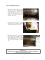
4.4 Changing Filter Paper (cont.)
4.
Remove and check the support screen
for cleanliness and scrub if
necessary. Ensure there is no buildup of shortening around the nipple
assembly.
5.
Check the filter-pan for cleanliness
and scrub if necessary; check the
drain ports at the bottom rear of the
filter pan also.
Solidified shortening build-up around and in
nipple-pipe assembly.
6.
Replace the filter support screen and
place a new sheet of filter paper on
top of the screen.
Place the
previously used sheet of filter paper
over the new sheet.
4-4
4.4 Changing Filter Paper (cont.)
7.
Replace the hold-down ring and
secure.
8.
Replace filter pan cover.
4.5 Unit Operation
1. When filtering, follow these steps:
2. Follow the appropriate Sections 4.3 and 4.4 to prepare your filter for operation.
3. Then position filter under fryer drain valve extension for gravity drain, or near the fryer if
the unit is an “AU” unit.
4. Turn the fryer main power switch to the “OFF” position.
WARNING
Do not leave filter unit unattended during the filtering operation. Pressurized
oil moving through the lines can cause the flexible return hose and wand
assembly to pop loose and leak hot oil.
Avoid spilling hot oil onto floor surfaces. Never drain more than the maximum
amount of oil listed on the filter pan.
5. If filter is equipped with an optional heater, turn the filter switch to the heater position for
20 minutes before filtering in order to melt any solid shortening in the pump lines.
4-5
4.5 Unit Operation (cont.)
6. Open the fryer door and ensure the filter is in the proper position under the fryer drain
valve extension. Lock rear casters to prevent filter movement during the filtering
process.
WARNING
The oil temperature of the fryer to be filtered should be approximately 350°F
(175°C). Position drain handles properly prior to operating the filter unit.
Failure to do this can result in burn injury to the user.
7. Open the drain- valve and allow the fry
vessel oil to drain into the filter pan.
4-6
4.5 Unit Operation (cont.)
8. With oil return nozzle in the vessel, turn
filter switch “ON” to begin pumping
clean oil into the fryer. Allow the oil to
recycle through the fryer for a few
seconds to wash out sediment on the
bottom of the cooking vessel before
closing the drain valve.
9. Close the drain valve handle. It takes
approximately 5 to 7 minutes for the filter
to pump all the oil back into the fryer.
10. Allow the pump to run for 10-15 seconds
after air starts to flow through the wand,
before shutting off the filter. Clearing
residual shortening/oil from the return
lines reduces the likelihood of clogged
lines.
CAUTION
Operating the fryer without oil in the fryer vessel will cause damage to the
fryer and the warranty will be voided.
4-7
4.5 Unit Operation (cont.)
NOTE: After filtering, scrape off debris and sediment accumulated on the filter paper and
discard.
CAUTION
If using solid shortening, the return hose must be completely drained after
filtering, or the shortening will solidify and plug the hose or oil return lines as
it cools.
NOTE:
If filtration operations problems are encountered during use, please refer to
Chapter 6 in this manual.
4-8
DEAN PORTABLE MICRO-FLO OIL FILTRATION SYSTEMS
CHAPTER 5: CLEANING AND MAINTENANCE
5.1 General
Cleaning operations fall into three general categories:
?? Wiping unit clean after each filter session;
?? Cleaning, changing filter paper and preparing the unit for the next day’s business.
?? Weekly cleaning to remove oil deposits and other particles that were previously
missed.
WARNING
Do not use water jets to clean this equipment.
CAUTION
Never operate the filter unit unless cooking oil is at operating temperature.
5.2 Each Filter Use
Every time your Portable Filter System is used:
?? Wash down the insides of the filter pan with hot oil.
?? Change the top filter paper sheet after each filter session or at the end of the day.
Scrape sediment from the top sheet after each frypot is filtered within a filter session.
?? Wipe up any oil which may have splashed or spilled.
?? Wipe all exterior surfaces of the filter unit.
CAUTION
Do not run water or boil-out solution through the filtration system. Doing so
will cause irreparable damage to the pump, and the warranty will be voided.
5-1
5.3 Daily- Close Of Business
At the close of a working day, the last order of business should be to filter the oil in all fryers.
When the last fryer is finished, follow these steps:
1.
Ensure the flexible hose and pump lines are clear by running the filter pump for an
additional 10–15 seconds after air bubbles start coming from the oil return line. Then
drain the flexible hose.
2.
Remove the filter pan cover and hold-down ring assembly, then remove the filter
paper and filter support screen.
3.
Discard the top filter paper sheet and retain bottom filter paper sheet for re-use.
4.
Wash all filter components with soapy water and rinse.
5.
Dry all filter parts and filter pan thoroughly before reassemb ling.
6.
Check all fittings at the rear of the filter unit; ensure that all fittings are properly
tightened.
CAUTION
The crumb tray in portable filter systems must be emptied into a fireproof
container at the end of frying operations each day. Some food particles can
spontaneously combust if left soaking in certain shortening material.
5.4 Weekly
Follow the same procedure as for “Daily”, with these additional steps:
?? Wash the filter pan with hot, soapy water and a brush. Dry and reassemble with new
filter paper.
?? Clean thoroughly under, around, and behind the fryers and filtering area.
?? Do not operate motor/pump until all traces of water have been removed from the
pan. Under no circumstances should water or boil-out solution be allowed to enter
the pump housing.
?? Check the connections of the inlet lines and tighten if lines become loose or start to
leak oil.
5-2
DEAN PORTABLE MICRO-FLO OIL FILTRATION SYSTEMS
CHAPTER 6: TROUBLESHOOTING
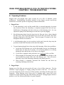
6.1 Operating Problems
Plugged lines and plugged filter paper account for over 90% of filtration system
malfunctions. Troubleshooting flowcharts included in this chapter, provide step-by-step
instructions to assist the operator in diagnosing common malfunctions.
A. Plugged Lines
1.
If solid shortening is used, and the portable filter is operated improperly, the motor
may deactivate before hot shortening is completely pumped back into the fryer.
Solidification of shortening in the lines will occur as the shortening cools. It is very
important to pump all hot shortening out of the lines to prevent plugging.
2.
Hot oil/shortening drains from the frypot into the filter pan, then is drawn through
the filter paper, exits the pan through the ports on the filter pan bottom, then flows
through a rigid tube to the filter pump. From the pump, oil returns to the fryer
through the flexible oil return hose.
3.
A solid-shortening plug can exist anywhere in this path; locate the plug using the
procedures found in the flowcharts at the end of this chapter
4.
To guard against plugged lines when using solid shortening, follow these guidelines:
a.
At the end of the filtering cycle, let the filter bubble into the fryer through the
flexible hose for about 10-15 seconds. If it is blowing bubbles, air is moving
through the lines and the filter is less likely to be plugged.
b.
If your filter is equipped with a pan heater, use it each time before you filter.
c.
When pumping hot shortening back into the fryer, tilt the filter machine to the
rear for about ten seconds at the end of the filtering cycle. This will remove
about three cups of hot shortening remaining in the bottom port area.
d.
When filtering is completed, disconnect the flexible line and drain any
remaining shortening from the line.
B. Plugged Paper
Improper use of the filter pre-coat powder will cause a slow oil flow return rate. The first
indication of paper plugging is a surging, jerking movement of the hose. To correct this,
review the instructions for the correct use of filter powders, and change the filter paper more
frequently. When filtering several fryers prior to changing paper, ensure that excess
sediment is scraped off the filter paper after filtering each frypot. If plugged paper remains a
problem, review the following flowcharts for proper diagnosis.
6-1
6.2 Troubleshooting Flowcharts
The following flowcharts contain information to assist the user in diagnosing the most
common malfunctions with portable filtration systems. Possible solutions and/or corrective
actions are given for each scenario.
When utilizing these flowcharts, begin at the top of the diagram, then follow each step in
sequence. Follow the arrows directing you through the sequence of steps, until you find the
cause of the problem. If the malfunction cannot be diagnosed using the flowcharts, contact
your Factory Authorized Service Agent for repairs.
DANGER
Use extreme care when working with or during electrical circuit tests. Live
circuits will be exposed.
DANGER
Inspection, testing and repair of gas or electrical equipment should be
performed by qualified personnel.
6-2
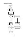
Filter Pump Fails To Pump Oil
Filter
pump
fails to
pump
oil.
If filter unit has a
heater, turn heater
ON and allow to
heat for 20
minutes.
Disconnect flexible oil return
hose. Make sure it is cool before
handling. Try blowing air through
the hose.
Can you blow
air through it?
No
Submerge hose in very hot water,
keeping the water out of the hose.
Water in the hose will cause severe
splattering when hot oil is circulated
through the hose.
Yes
Insert flexible oil
return hose into
filter pan and turn
pump motor ON.
Does oil flow through oil
return hose?
Once shortening has had time
to soften, reconnect hose to
filter pump.
No
Blockage is between bottom of the filter
pan and the flexible hose quick
disconnect. Go to "Blockage Between
Filter Pan and Flex Hose Valve.
Yes
Proceed with normal
operations.
6-3
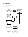
Rate Of Oil Return Slowing
Rate of oil return to fryer is slowing.
Is this the first fryer being filtered
during this filtering session?
No
Check for excess
sediment build-up
on filter paper
Disassemble unit and wipe
excess sediment out of the
bottom of filter pan "sump", and
remove any sediment from
drain ports in pick-up tube.
Yes
Install new filter paper.
Check the condition
of the filter paper in
filter pan
Is filter paper properly
secured in filter pan
No
If paper is incorrectly
installed under hold-down
ring, air may be getting into
the system.
Yes
Replace filter paper, and reinstall
hold-down ring.
Add the correct amount
of filter powder and
reassemble filter.
Turn motor ON. Has the oil rate
improved?
No
Blockage may be between
the bottom of the filter pan
and the flexible hose
quick-connect
Yes
Proceed with
filtration
Go to "Blockage Between Filter Pan and
Flex Hose Valve".
6-4
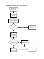
Blockage Between Filter Pan and Flex-Hose Valve
Possible blockage
between filter pan
bottom and flex-hose
disconnect.
Disconnect oil line from
filter pan to pump at the
pump end.
Turn pump ON and allow it to
operate for a few seconds to ensure
it does not run backwards.
Put your finger over the
pump inlet. Is suction
present?
No
Blockage is in pump or in
the discharge line.
Yes
Pump is clear; plug is
in the bottom of the
filter pan or in the line
from the pan to pump.
Disconnect line at filter pan.
Can you blow air through line
from pump to pan?
No
Line is blocked. Remove
line, soften and clear
solidified shortening.
Yes
Reconnect line and
operate pump. If still
no oil flow, blockage
is in bottom of pan.
Remedy problem and continue
filtration process.
6-5
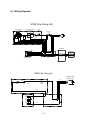
6.3 Wiring Diagrams
MF90 Filter Wiring (AU)
OFF/ON HEATER SWITCH
(OPTIONAL)
PUMP REVERSING
SWITCH
TIMER
SWITCH
INDICATOR
LIGHT
OPTIONAL
BLK
BLK
GRN
WHT
CB
2 AMP
FUSE
7 AMP
RED
RED
BLK 1
BLK 4
BLK 8
BLK 5
SWITCH HOUSING
RED
OPTIONAL
BLK 5
BLK 8
T5
T8
T1
T4
OPTIONAL
BLK 4
BLK 1
RED
WHT
WHT
Junction
Box
MOTOR
TERMINAL BOX
Suction Sump
Heater
One Way Valve
Heater
MF90 Filter Wiring (U)
POWER CORD
AWG 16-3 SJT
BLK
BLK
PUMP
SWITCH
CB
TIMER
SWITCH
7 AMP
BLK
P1
P2
T3
T5
T2
T4
T8
BLK
WHT
6-6
GRN
WHT
DEAN PORTABLE MICRO-FLO OIL FILTRATION SYSTEMS
CHAPTER 7: PARTS LIST
7.1 MF-90/65, U and AU Configuration
7-1
7.1 MF-90/65, U and AU Configuration (cont.)
ITEM
1
2
3
4
5
6
7
8
9
10
*
*
11
12
*
13
14
15
16
17
18
19
20
*
21
22
23
24
25
26
27
28
29
30
*
31
32
33
34
35
36
37
PART #
44272-1
44-0409
1004
1008
1005
2376
2736
1832
1709
44267
44267-2
44267-1
1025
1892-2
1726-1
1059
1013
2083
1989
1014
55016
1350
44287
55220
1687
1061
1765
1012
1057-SC
1011
1076
44291
1644
1798
1799
1043
44-0379
1100A
55-0004
1010
2124
1985
COMPONENT
Frame Assembly
Caster Channel
Bolt, ¼ - 20 x ½- inch Hex
Washer, Flat ¼- inch
Nut, Nylock ¼-20
Caster, 3- inch, w/o Brake
Caster, 3- inch w/Brake
Washer, Flat, ½- inch
Nut, ½-13 Hex
Electric Box Assembly (U65 w/o Heater)
Electric Box Assembly (AU/65 w/Heater)
Electric Box Assembly (U/65 w/Heater)
Screw, #8 x ½ Type B
Motor, 1/3HP 230/120V/50/60Hz
Pump, 5 GPM (18 LPM)
Nipple, Black Pipe ½ x 1-½- inch
Elbow, ½ x 3/8- inch 90° Black Pipe
Nipple, 3/8 x 3-½ -inch
Elbow, 3/8 x 45°
Nipple, Black Pipe, 3/8" x Close
Couple Assembly (Snap-Tight)
Seal, Viton Quick-Disconnect
Nozzle and Hose Assembly, Complete
Nozzle and Hose Assembly
Elbow, Street, Black Pipe, ½- inch x 90°
Union, Black Pipe, ½- inch
Tee, Black Pipe, ½ x 3/8 x ½- inch
Nipple, Black Pipe [ ½ NPT x 6- inch]
Check Valve, Swing ½-(Plated)
Elbow, Black Pipe, ½-inch x 90°
Nipple, Black Pipe ½NPT x 3-½-inch
Hose Assembly w/Fitting (L= 11.75- inch)
Quick-Disconnect Male ½- inch
Nipple, Black Pipe, [3/8NPT x 2- inch]
Nipple, Black Pipe [3/8NPT x2-½- inch ]
Elbow, 3/8- inch x 90°
Holder, Power Cord
Valve, Ball- 3/8-inch
Bolt, Hold-down Handle
Nipple, Black Pipe, ½- inch x Close
Nipple, Black Pipe[3/8 NPT x 7- inch]
Flare Fitting 3/8- inch NPT
7-2
7.1 MF-90/65, U and AU Configuration (cont.)
ITEM
38
39
40
41
*
*
42
*
*
43
44
45
46
47
48
49
50
51
52
53
*
54
55
56
57
58
59
60
61
62
63
*
64
65
66
67
68
69
70
71
72
*
73
PART #
1036
1037
1034
55-0007
1081
1678
1385
1083
1541
44-0443
1856
44268
1032
2081
1096
1092
1098
2053
2059
2036
2175
44282
44285
1033
2009
1391
1075
55191
1645-1
55156
1334-PK
1334
55127
55-0011
44262
1016
55228-SC
55-0121
44-0450
55-0264
44286
44-0447
1039
COMPONENT
Nut, ½- inch Flare 37°
Tubing Sleeve ½- inch 37°
Tube, SS, [ ½- inch Diameter x Feet]
Plate, IN-OFF-OUT (AU Only)
Plate, PUMP-OFF-HEAT (with Heater Option)
Plate, ON-OFF (U Only)
Switch, 3PDT 90 Amp Push ON
Switch, Toggle SPDT (U Only, With Heater Option)
Switch, Toggle (U Only, No Heater Option)
Handle, Ball Valve, (3/8- inch)
Clamp, Pipe ½- inch (Jiffy H-40)
Holster, Hose Assembly
Screw, 10-32 x ½- inch Round Slotted Head
Clamp, Draw (HR-1)
Connector, 3/8- inch x 45°
Connector, 3/8- inch x 90°
Conduit, 3/8- inch Flex
Inlet Flanged Base 120V
Power Cord,1613 SJTO
Circuit Breaker (7 Amp- 120V Applications)
Circuit Breaker (5 Amp- 230V Applications)
Motor/Pump Cover Assembly (AU-65)
Filter Pan Assembly (U/AU-65 /Clamp)
Screw, ¼-28 x ½ Round Phillips Head
Nipple, Black Pipe [ ½ NPT x 2-½ -inch]
Elbow, ½- inch, 45° Black Pipe
Nipple, Black Pipe ½NPT x 3-inch
Quick Disconnect Assembly ( ½-inch)
O-Ring
Wire Grid and Channel Assembly (#12)
Filter Paper, 11 x 22-5/8 (20 Sheets/Pack)
Filter Paper, 11 x 22-5/8 (100 Sheets/Pack)
Hold-Down Ring w/Handle Assembly
Lever, Hold-Down Ring
Pan Assembly, w/o clamps
Connector, Male 3/8”
Handle Assembly
Nozzle, Threaded (One End)
Nozzle, Threaded (Both Ends)
Pipe Screen
Pan, Lid Assembly
Pan Lid Only
Handle, Filter Pan Lid (w/Screws)
7-3
7.1 MF-90/65, U and AU Configuration (cont.)
ITEM
PART #
COMPONENT
74
44273
Heater Junction Box
75
44561
8" Strip Heater w/Bracket Weld Assembly**
76
44-0425
Pan Slide, Electric Motor
77
1031
Nut, Nylock (#10-32
*
44274
Rear Heater Guard Assembly
79
44-0828
Pipe Support
*
44-0837
Back , Filter Cover
*
55546
Crumb Basket, MF90/65
*
2174
Glove, Neoprene, (Hot-oil)
*
8030002
Filter Powder
*
1049
Measuring Cup, 16 Oz.
*
55030
Scoop Assembly (Small)
* Not Illustrated
** For probe heater components, see Section 7.2.1.
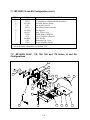
7.2 MF-90/80, 80-LP, 110, 126, 160 and 172 Series, U and AU
Configurations
24
20
23
16
21
22
17
18
14
26
27
28
19
13
25
11
12
5
4
6
10
8
15
9
7
7-4
3
2
1
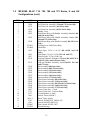
7.2
MF-90/80, 80-LP, 110, 126, 160 and 172 Series, U and AU
Configurations (cont.)
ITEM
1
*
*
*
2
3
PART #
55084
55086
55135
55438
1039
55083
*
55033
*
55308
4
5
6
55-0011
55-0004
1038
*
*
7
1054
1053
55120
*
55121
8
*
*
*
*
*
*
*
*
*
*
9
*
10
11
12
13
*
*
14
55190
55437
55189
55059
55187
55186
55019
55020
55021
55046
55022
1003
2734
2175
1026
1026-1
1385
1083
55-0007
55-0029
COMPONENT
Lid, Filter Pan Assembly, (80 and 110 Series Only)
Lid, Filter Pan Assembly, (126 and 172 Series Only)
Lid, Filter Pan Assembly (160 Series Only)
Lid, Filter Pan Assembly (80-LP Series Only)
Handle, Cover
Hold-Down Ring with Handle Assembly Standard (80
and 110 Series Only)
Hold-Down Ring with Handle Assembly, Jumbo (126,
160 and 172 Series Only)
Hold-Down Ring with Handle Assembly (80-LP Series
Only)
Locking Lever, Hold Down Ring
Latch Bolt
Filter Paper 16-3/8 x 18-3/8" (80, 80-LP And 110
Only)
Filter Paper, 16-3/8 x 24-3/8 (126, 160 And 172)
Filter Powder, 22,7kg (50 lb.) bag
Grid and Channel Assembly, Standard [80, 80-LP (UL
AND CE Only) and 110 Series Only]
Grid and Channel Assembly, Jumbo (80-LP, 126, 160
and 172 Only)
Pan Assembly (80 Series Only)
Pan Assembly (80-LP Series Only)
Pan Assembly (110 Series Only)
Pan Assembly (126 Series Only)
Pan Assembly (160 Series Only)
Pan Assembly (172 Series Only)
Filter Frame Assembly (80 Series Only)
Filter Frame Assembly (110 Series Only)
Filter Frame Assembly (80-LP and 126 Series Only)
Filter Frame Assembly (160 Series Only)
Filter Frame Assembly (172 Series Only)
Caster, Filter Pan— 2-inch
Caster, Filter Pan—2-inch w/Brake
Circuit Breaker (5 Amp)
Switch, Timer (60 Min.)
Knob, Timer Switch
Switch, IN/OFF/OUT (MF90-AU)
Switch, ON/OFF (MF90-U)
Plate, Switch IN-OFF-OUT
Switch Housing
7-5
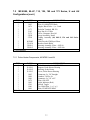
7.2
MF-90/80, 80-LP, 110, 126, 160 and 172 Series, U and AU
Configurations (cont.)
ITEM
15
*
16
17
18
19
20
21
22
*
*
23
24
*
25
26
27
28
*
*
*
*
*
*
*
*
*
*
*
*
*
*
*
*
*
*
*
*
*
*
*
PART #
55217
55246
1057-SC
55-0064
55016
1016
1726-1
1892-2
1021
6136
2563
55-0070
55-0065
55-0066
55-0068
55210
55228-SC
55115
55220
55245
1004
1005
1008
1009
1010
1011
1013
1014
1019
1020
1022
1025
1027
1028
1029
1030
1031
1032
1035
1058
1059
COMPONENT
Suction Tube, Pan to Filter Pump ("U" Series Only)
Suction Tube, Pan to Check Valve ("AU" Series Only)
Valve, Swing Check 1/2"(Plated) ("AU" Series Only)
Motor Mount Tray
Coupler Assembly (Snap-Tight)
Male Coupler
Pump, 5 GPM (18 LPM)
Motor, 1/3HP 230/120V/50/60Hz
Power Cord 10' 16/3 SJTO Black
Power Cord 16/3 SJTO(W)
Receptacle, 230V, 3-Prong
Bracket, Handle Cord
Housing, Top Cover
Housing, Back Cover
Motor Housing
Hose Only, with Fittings
Handle Assembly
Nozzle with Handle
Nozzle and Hose Assembly, Portable Filter
Harness Assembly, "A" Type Filter
Bolt, ¼ - 20 x ½- inch Hex
Nut, Nylock ¼-20
Washer, Flat ¼- inch
Washer, Lock ¼- inch
Nipple, Black Pipe, ½- inch x Close
Elbow, Black Pipe, ½-inch x 90°
Elbow, ½ x 3/8- inch 90° Black Pipe
Nipple, Black Pipe, 3/8" x Close
Ring Terminal #8
Connector, Romex— 3/8"
Ring Terminal #10
Screw, #8 x ½ Type B
Screw 8-32 x ½ Round Slotted Head
Lock-nut, #8-32 Hex
Plug Button ½- inch Nickel-Plated
Wire Joint RC-6
Nut, Nylock, #10-32
Screw, 10-32 x ½- inch Round Slotted Head
Fitting, 37°, Flare, ½- inch
Tee, Black Pipe ½
Nipple, Black Pipe ½ x 1-½- inch
7-6
7.2 MF-90/80, 80-LP, 110, 126, 160 and 172 Series, U and AU
Configurations (cont.)
ITEM
*
*
*
*
*
*
*
*
*
*
*
*
* Not Illustrated
PART #
1061
1063
1074
1173
2165
2174
55030
55218
8030002
55-0130
55089-1
55089-2
COMPONENT
Union, Black Pipe, ½- inch
Wire 16 AWM/TEW Black
Nipple, Black Tube—½ x 5- inch
Push-On Terminal, RB 250
Kep-Nut #10-32 Hex
Glove, Neoprene, Hot-Oil
Scoop Assembly, Small
Tubing Assembly (80, 80-LP, 126 and 160 Series
Only)
Filter Powder, FM/Dean Filters
Bracket, Strain Relief
Housing Assembly, Filter— MF-90
Housing Assembly, Filter— MF-90A
7.2.1 Probe Heater Components, All MF90 U and AU
ITEM
*
*
*
*
*
*
*
*
*
*
*
*
* Not Illustrated
PART #
1957
X-424-1
X-424-2
X-424-3
1095
1098
1096
1678
1082
1541
1960
1081
COMPONENT
Probe Heater ¼ x 6 x ¼ NPT 120V
Support, Probe Heater Housing
Housing, Probe Heater
Cover, Probe Heater Housing
Connector, Lt, 3/8" Straight
Conduit, 3/8 Flex Lt
Connector, Lt, 3/8" x 45°
Plate, ON-OFF
Light, Indicator (Red)
Switch, Toggle
Tee, Black Pipe, ½ x ¼ x ½
Plate, PUMP-OFF-HEAT
7-7
Dean, 8700 Line Avenue, PO Box 51000, Shreveport, Louisiana 71135-1000
Shipping Address: 8700 Line Avenue, Shreveport, Louisiana 71106
TEL 1-318-865-1711
PRINTED IN THE UNITED STATES
FAX (Parts) 1-310-327-3343
SERVICE HOTLINE
1-800-551-8633
FAX (Tech Support) 1-318-219-7135
Price: $6.00
819-5808 10-00