1
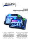
ATHON GPS RW ATHON GPS PRO Installation and operation manual. Manuale d’installazione e uso. ATHON GPS is an automatic chrono developed with GPS technology and process algorithms used in the most advanced airborne systems. Its features make it the most advanced, complete and easy instrument for all the drivers of: Go Karts - Cars - Motorbikes and Scooters. ATHON GPS è un cronometro automatico basato su tecnologia GPS e algoritmi di calcolo utilizzati nei più moderni sistemi dell'aviazione. Le sue caratteristiche lo rendono lo strumento più avanzato, completo e semplice per tutti i piloti di: Go Kart - Auto - Moto - Scooter. Contents Contenuti Introduction ................................................................. 3 Functions ..............................................................................3 Introducing the GPS technology ..........................................3 Front Panel ...........................................................................4 Installation of ATHON GPS ........................................... 5 Assembly ..............................................................................5 Power supply ........................................................................6 Connection with the 12V battery of the vehicle ............6 Power supply with external batteries (optional)...........6 ATHON GPS RW Electrical connections ...............................7 ATHON GPS PRO Electrical connections..............................8 Connecting the engine RPM reading wire.........................10 Direct electrical connection ..........................................10 Ignition coil Inductive reading.......................................10 Water Temperature ...........................................................11 Updating the ATHON firmware .........................................12 Checking the Firmware version installed .....................12 Downloading the update ..............................................13 Usage ..........................................................................13 Turning ON/OFF the device ...............................................13 Multi-page menu................................................................13 GPS signal acquisition ........................................................14 Configuration......................................................................14 Setting the Freeze Time ................................................14 Setting the RPM reading parameters ...........................15 Aligning the GPS clock to the local timezone ...............16 Setting the LED Bar and the Shift light..........................17 Selection of the units of measurement ........................17 Energy saving and Auto Power-Off....................................18 Track management ............................................................19 Learning the Finish Line and Intermediate positions ........................................................................19 Storing the coordinates of the Finish Line and Intermediate positions ..................................................20 Loading the track coordinates ......................................21 Analysis of the stored times..........................................22 Managing the Hour Meters ...............................................24 Resetting the Hour Meters ...........................................24 Memory Management .......................................................25 Session recording ..........................................................25 Checking the memory in use ........................................26 Introduzione................................................................. 3 Funzioni................................................................................ 3 Introduzione alla tecnologia GPS ........................................ 3 Pannello Frontale ................................................................ 4 Installazione di ATHON GPS.......................................... 5 Montaggio ........................................................................... 5 Alimentazione...................................................................... 6 Connessione alla batteria a 12V del veicolo .................. 6 Alimentazione con batterie esterne (optional) ............ 6 Connessioni elettriche ATHON GPS RW ............................. 7 Connessioni elettriche ATHON GPS PRO ............................ 8 Collegamento del filo di segnale regime motore (RPM) .. 10 Collegamento elettrico diretto .................................... 10 Lettura induttiva dalla bobina di accensione .............. 10 Temperatura acqua ........................................................... 11 Aggiornamento del firmware di ATHON .......................... 12 Verifica della versione di Firmware installata ............. 12 Scarico dell’aggiornamento.......................................... 13 Uso ............................................................................. 13 Accensione e spegnimento del dispositivo .............. 13 Menu multipagina ............................................................. 13 Acquisizione del segnale GPS ............................................ 14 Configurazione................................................................... 14 Impostazione del tempo di visualizzazione a fine giro 14 Impostazione dei parametri di lettura regime motore 15 Allineamento dell’orologio GPS con il fuso orario....... 16 Impostazione delle barra LED e del Flash di Fuorigiri . 17 Selezione delle unità di misura .................................... 17 Risparmio energetico e autospegnimento .......................... 18 Gestione circuiti................................................................. 19 Apprendimento della linea di traguardo e degli intermedi ...................................................................... 19 Memorizzazione delle coordinate di Traguardo e Intermedi ...................................................................... 20 Richiamare le coordinate di un circuito ....................... 21 Analisi dei tempi memorizzati...................................... 22 Gestione dei Contaore ...................................................... 24 Azzeramento dei Contaore .......................................... 24 Gestione della memoria .................................................... 25 Registrazione delle sessioni.......................................... 25 Verifica della memoria utilizzata.................................. 26 1 Memory clearing ...........................................................26 Memory Formatting ......................................................27 Computer connections.......................................................28 PC Pairing .......................................................................28 Protecting the Bluetooth Connection...........................31 Gear programming .............................................................32 Setting up the number of gears of the vehicle.............33 Gear learning .................................................................33 Setting up the Alarms.........................................................35 Temperature alarm activation ......................................35 Set up the Temperature alarm threshold.....................35 Cleaning the surfaces .........................................................36 Warranty.............................................................................36 Notes ..................................................................................36 Cancellazione della memoria ....................................... 26 Formattazione della Memoria ..................................... 27 Collegamenti con il computer ........................................... 28 Accoppiamento con il PC.............................................. 28 Protezione della Connessione Bluetooth .................... 31 Programmazione delle marce ........................................... 32 Impostazione del numero di marce del veicolo .......... 33 Apprendimento dei rapporti ........................................ 33 Impostazione degli Allarmi................................................ 35 Attivazione dell’allarme Temperatura ......................... 35 Impostare la soglia di allarme Temperatura................ 35 Pulizia delle superfici ......................................................... 36 Garanzia ............................................................................. 36 Note ................................................................................... 36 ATHON GPS PRO Advaced functions ...........................37 Acquisition channels managed by ATHON GPS-PRO ........38 Distinction between Analog and Digital channels........39 Channel setup.....................................................................39 Definition of Data Acquisition channels .......................39 Define the function of an Analog Channel ...................40 Calibration of analog sensors.............................................42 Calibration of the throttle position sensor ...................42 Calibration of linear potentiometers ............................44 Setting the speed reading parameters .........................47 Type K thermocouple Alarm ..............................................49 Type K thermocouple alarm activation ........................49 Set up the Temperature alarm threshold.....................49 Detecting the Cylinder Pressure and Detonation recognition .........................................................................50 Detonation + Cylinder Pressure Sensor Installation.....51 Definition of the Detonation channel...........................52 Calibration of the Detonation Counter.........................53 Setting the Detonation Counter sensitivity ..................55 Activate the Detonation alarm .....................................56 Set up the Detonation alarm threshold........................56 Funzioni avanzate ATHON GPS PRO ........................... 37 Canali acquisizione gestiti da ATHON GPS-PRO ............... 38 Distinzione tra canali Analogici e Digitali ..................... 39 Impostazione canali........................................................... 39 Definizione dei canali Acquisizione Dati ...................... 39 Definire la funzione di un Canale Analogico ................ 40 Calibrazione dei sensori analogici ..................................... 42 Calibrazione del sensore di apertura acceleratore ..... 42 Calibrazione dei potenziometri lineari......................... 44 Impostazione dei parametri di lettura della velocità .. 47 Allarme Termocoppia TK ................................................... 49 Attivazione dell’allarme Termocoppia TK.................... 49 Impostare la soglia di allarme Temperatura................ 49 Rilevamento della Pressione del Cilindro e riconoscimento della Detonazione ................................... 50 Installazione del sensore Detonazione + Pressione Cilindro .......................................................................... 51 Definizione del canale Detonazione ............................ 52 Calibrazione del Contadetonazioni .............................. 53 Impostazione della sensibilità del Contadetonazioni.. 55 Attivare l’allarme Detonazione .................................... 56 Impostare la soglia di allarme Detonazione ................ 56 2 Introduction Introduzione Functions Funzioni ATHON GPS carries out the following basic functions: ATHON GPS svolge le seguenti funzioni base: GPS Chrono. Cronometro GPS. Double Hour Meter. Doppio Contaore. Enginespeed indicator. Contagiri motore. GPS Tachometer. Tachimetro GPS. Clock. Orologio. Shift Light. Flash di Fuorigiri Engaged Gear indicator. Indicatore della marcia inserita. Water temperature sensor Sensore temperatura dell'acqua Inputs for optional sensors (ATHON GPS Pro only) The DigiRace Data Analysis Software is also supplied in the following versions: Ingressi per sensori opzionali (solo ATHON GPS Pro) Viene inoltre fornito il Software di Analisi Dati DigiRace nelle seguenti versioni: DigiRace-LE for ATHON GPS RW DigiRace-LE per ATHON GPS RW DigiRace-PRO for ATHON GPS Pro. DigiRace-PRO per ATHON GPS Pro. Introducing the GPS technology Introduzione alla tecnologia GPS GPS is the acronym of "Global Positioning System", a satellite positioning system for global and continuous coverage managed by the USA Defence Department. The navigation system is subdivided into the following components: GPS è l'acronimo di "Global Positioning System", un sistema di posizionamento satellitare, a copertura globale e continua, gestito dal dipartimento della difesa statunitense. Il sistema di navigazione si articola nelle seguenti componenti: a group of 24 operating satellites plus some spare ones un complesso di 24 satelliti in funzione più alcuni di scorta a network of ground stations for system management una rete di stazioni a terra per la gestione del sistema A GPS receiver Satellites elliptically orbit at a distance of about 20200 km so that at least 6 satellites can always be seen from any place on the earth. Every single satellite transmits a radio signal specifying exact time and its position to enable the GPS receiver – knowing the exact position of at least 4 satellites – to calculate the position of the receiver in un ricevitore GPS I satelliti orbitano a circa 20200 Km su orbite ellittiche in modo che almeno 6 satelliti siano sempre visibili in qualunque luogo sulla terra. Ogni satellite trasmette un segnale radio che indica l'ora precisa e la sua posizione. In tal modo il ricevitore GPS, conoscendo l'esatta posizione di almeno 4 satelliti rie3 the space, the current accuracy of which is usually guaranteed even below 1 m. The GPS positioning service is free for end users only requiring the GPS receiver to be able to use it. sce a calcolare la posizione nello spazio del ricevitore stesso, con una precisione attuale che arriva anche a livelli inferiori a 1 m. Il servizio di posizionamento GPS è gratuito per gli utenti finali, i quali necessitano solo del ricevitore GPS per poterlo utilizzare. Front Panel Pannello Frontale The LED Bar, the Best Lap LED, the three blue high power LEDs of the shift light, the back-lit display and the 4-key keypad are located on the front panel. Sul Pannello Frontale si trovano la Barra LED, il LED Best Lap, i tre LED Blu ad alta luminosità del Flash di Fuorigiri, il display retroilluminato e la tastiera a 4 tasti. Press the key to choose the main screen you wish among the various ones made available for your ATHON GPS model. The “Best Lap” LED is a very useful function to immediately give immediate information on a better performance without distracting the driver by making him read the display. Premendo il tasto è possibile scegliere la schermata principale preferita tra le varie disponibili per il vostro modello di ATHON GPS. Il LED “Best Lap” è una funzione molto utile per dare informazioni immediate sul miglioramento della prestazione senza distrarre il pilota per la lettura del display. Il LED “BEST LAP” si illumina fisso se viene migliorato il tempo rispetto al giro precedente. If the “BEST LAP” LED lights on it means a better time compared to the previous lap. Il LED “BEST LAP” lampeggia se il giro 4 If the “BEST LAP” LED blinks it means you have just closed your best lap time of the session in progress. The “BEST LAP” LED also works for the intermediates if they have been set. appena concluso è il migliore della sessione in corso. Il LED “BEST LAP” funziona anche al passaggio sugli Intermedi se questi sono stati impostati. Installation of ATHON GPS Installazione di ATHON GPS Assembly Montaggio ATHON GPS is easily installed in the windshield of a Motorbike, on the fork plate, on the steering wheel of a Go Kart, or on the dashboard of a Car. Fix ATHON GPS with supplied adhesive Dual Lock System or the elastic support kit. ATHON GPS si installa facilmente nel cupolino di una moto, sulla piastra forcella, sul volante di un Go Kart, o sul cruscotto di un’auto. Fissare ATHON GPS con il sistema Dual Lock a strappo fornito o con il kit di supporti elastici. IMPORTANT: To protect ATHON GPS against vibrations, never fix it rigidly to the vehicle and make sure it will never be in contact with any rigid part thereof. IMPORTANTE: Per proteggere ATHON GPS dalle vibrazioni, non fissarlo mai in modo rigido al veicolo e controllare che non abbia alcuna parte in contatto con organi rigidi del mezzo. 5 Power supply Alimentazione You can supply ATHON GPS by means of a 12V battery of the vehicle or the specific external accessory batteries. È possibile alimentare ATHON GPS tramite batteria a 12V del veicolo oppure con le specifiche batterie esterne accessorie. Connection with the 12V battery of the vehicle Connessione alla batteria a 12V del veicolo Connect the Red wire of the extension cable provided with the 12V Positive of the vehicle battery and the Black wire with an earth point on the frame or, even better, directly with the Negative of the battery. Collegare il filo Rosso della prolunga fornita al Positivo 12V della batteria del veicolo e il filo Nero ad un punto di massa sul telaio o, meglio ancora, direttamente al Negativo della batteria. Power supply with external batteries (optional) Alimentazione con batterie esterne (optional) Connect the ATHON GPS supply connector with the external accessory battery. Connect the negative battery pole with the vehicle chassis by using the cable supplied with the battery. Collegare il connettore di alimentazione di ATHON GPS con la batteria accessoria esterna. Collegare il polo negativo della batteria al telaio del veicolo utilizzando il cavo in dotazione con la batteria. 6 ATHON GPS RW Electrical connections Connessioni elettriche ATHON GPS RW Green cable: signal from the speed sensor for gear recognition. Violet cable: engine rev signal from the tachometer or the inductive readout of the ignition coil. Orange cable: +12V signal from the ignition key block to automatically power on the device when the key is turned on. Cavo verde:segnale proveniente dal sensore velocità per il riconoscimento delle marce. Cavo viola: segnale dei giri motore proveniente dal contagiri oppure dalla lettura induttiva dalla bobina di accensione Cavo arancione: segnale +12V dal blocchetto della chiave di accensione per impostare l’accensione automatica del dispositivo quando riceve alimentazione. NOTE: ATHON GPS must be any way supplied by the battery. NOTA: ATHON GPS deve comunque essere alimentato dalla batteria. 7 ATHON GPS PRO Electrical connections Connessioni elettriche ATHON GPS PRO ATHON GPS-PRO is supplied with a socket connector hub (DABOX) for the various sensors. Its installation is simple and prompt and no harness is required. After having connected the DABOX with ATHON GPS-PRO through a specific 14pole connector, just connect the various sensors directly with the inputs specified on the DABOX. Extensions of various lengths are available as an accessory to provide for the correct connection of the sensors on any type of vehicle. ATHON GPS-PRO viene fornito con una scatoletta di derivazione (DABOX) per i vari sensori che ne consente la semplice ed immediata installazione senza necessità di scomodi cablaggi. Una volta collegata la DABOX ad ATHON GPS-PRO attraverso lo specifico connettore a 14 poli, sarà sufficiente connettere i vari sensori direttamente agli ingressi specifici indicati sulla DABOX. Sono disponibili come accessorio prolunghe di varie lunghezze per consentire il corretto collegamento dei sensori su ogni tipo di veicolo. NOTE: To detect the signal from the original sensors properly, ATHON’s earth shall be also shared by the vehicle. NOTA: Per il corretto rilevamento del segnale dai sensori originali è necessario che la massa di ATHON sia in comune con quella del veicolo. A connection example is supplied below: Di seguito un esempio di connessione: 8 9 Connecting the engine RPM reading wire Collegamento del filo di segnale regime motore (RPM) Direct electrical connection Collegamento elettrico diretto NOTE: Make sure that the ATHON GPS Negative is connected with the vehicle earth. NOTA: Assicurarsi che il negativo di ATHON GPS sia connesso alla massa del veicolo. Option A: Peel and hardwire the black extension cord RPM1 directly with the signal wire (0-12 Volt) of the original RPM indicator and connect it with the ATHON GPS Violet wire.(see the figure of section "ATHON GPS RW Electrical Connections"). Opzione A: Spelare e saldare il filo Nero di prolunga RPM1 direttamente al filo di segnale (0-12Volt) del contagiri originale e connetterlo al filo Viola di ATHON GPS (vedi figura sezione " Connessioni elettriche ATHON GPS RW"). Attention! On some vehicles the signal of the original speed indicator is not of a 0-12 Volt type, but it directly comes from the power input wire of one of the ignition coils. This connection would damage the internal ATHON GPS circuit. Attenzione! Su alcuni veicoli il segnale del contagiri originale non è di tipo 0-12 Volt ma arriva direttamente dal pilotaggio di potenza di una delle bobine di accensione, tale collegamento danneggerebbe il circuito interno di ATHON GPS. Ignition coil Inductive reading (no electrical connection) Lettura induttiva dalla bobina di accensione (senza connessione elettrica) Option B1: In the case of Internal Coils built in the cylinder head wind the ATHON RPM1 extension cable with at least 8 turns round the input wires of one of the coils (see Picture, option B1). If the speed readout is not correct, increase the number of turns and check the settings indicated in the paragraph “Setting the RPM reading parameters” in this manual. If there are unexpected flashes of the shift light or incorrect instantaneous values, check the Black wire to ensure that it does not receive any interference from the cables of other cylinders, and therefore to make sure that the wire goes through parts of the chassis far from other coils and, if possible, it can be cut to the required length so that it does not receive any undesired signals. Option B2: In the case of External Coils, use the RPM2 extension. Just put it in contact Opzione B1: In caso di Bobine Integrate nella testata motore avvolgere la prolunga RPM1 di ATHON GPS con almeno 8 spire attorno ai fili di pilotaggio di una delle bobine (vedere Figura, opzione B1). Se la lettura del regime non è corretta, aumentare il numero delle spire e controllare le impostazioni nel paragrafo “Impostazione dei parametri di lettura regime motore” nel presente manuale . Se si riscontrano accensioni anomale del Flash di Fuorigiri o valori istantanei non corretti,controllare che il filo Nero non riceva interferenze dai cavi di altri cilindri, verificare quindi che percorra parti del telaio lontane da altre bobine e, se possibile, può essere accorciato alla lunghezza necessaria in modo che non riceva segnali indesiderati. Opzione B2: In caso di Bobine Esterne utilizzare la prolunga RPM2, che sarà suffi10 with the high-voltage coil cable (see figure, option B2) and fasten it by means of two clamps. ciente appoggiare a contatto con il cavo di alta tensione della bobina (vedere Figura, opzione B2) fissandola con due fascette. Attention! Never connect the RPM reading wire directly to the coil wire to prevent any inadequate voltage irreparably damaging the instrument. Attenzione! Non connettere mai il filo di rilevamento regime motore direttamente ai fili delle bobine poiché le tensioni inadeguate danneggerebbero lo strumento irreparabilmente. Water Temperature Temperatura acqua ATHON GPS is able to measure the cooling water temperature. You can connect the optional liquid temperature sensor (code CH2OM10) with the cable having the same connector and match it with a sleeve for installation on the rubber pipe between the water pump and the radiator. The sleeves are available as accessories for the various pipe diameters: 10 mm. (cod. MAN10), 19 mm. (cod. MAN19), 26 mm. (cod. MAN26). ATHON GPS permette il rilevamento della temperatura del liquido di raffreddamento. È possibile collegare al cavo con eguale connettore il sensore di temperatura liquido opzionale (cod.CH2OM10) abbinabile ad un manicotto da installarsi sul tubo di gomma tra la pompa dell’acqua ed il radiatore. I manicotti sono disponibili come accessori per i vari diametri di tubo: 10 mm. (cod. MAN10), 19 mm. (cod. MAN19), 26 mm. (cod. MAN26). ATHON GPS is compatible with its own sensor only. ATHON GPS è compatibile solo con il proprio sensore. 11 Updating the ATHON firmware Aggiornamento del firmware di ATHON The software installed inside ATHON and intended to manage all functionalities is referred to as Firmware. You can update the firmware when new versions with additional implementations and/or improvements are made available by Starlane. Il software installato all’interno di ATHON e che ne gestisce tutte le funzionalità ha il nome di Firmware. È possibile aggiornare il Firmware quando ne siano rese disponibili da Starlane nuove versioni con implementazioni aggiuntive e/o migliorie. Checking the Firmware version installed Verifica della versione di Firmware installata The Firmware version installed is displayed on the right corner at the bottom of the initial screen of your ATHON. Nell’angolo in basso a destra della schermata di avvio del vostro ATHON è indicata la versione di Firmware installata. VERSIONE FIRMWARE FIRMWARE VERSION You can check the exact model, the software version (firmware) and the serial number (for the models on which it is available) by accessing the System Info screen: È possibile verificare l’esatto modello, versione di software (Firmware) e numero di serie (per i modelli su cui disponibile) accedendo alla schermata System Info: 12 Downloading the update Scarico dell’aggiornamento Check on the technical support page of the www.starlane.com web site whether more up-to-date Firmware or DigiRace versions (the version number is higher) are available for your device. Follow the procedure described by the DigiRace software manual to download and install the latest Firmware update. Verificare sulla pagina di supporto tecnico del sito www.starlane.com la disponibilità di versioni più aggiornate (numero di versione più alto) del firmware per il vostro dispositivo nonché la relativa versione aggiornata di DigiRace. Seguire la procedura indicata sul manuale del software DigiRace per eseguire correttamente l’aggiornamento all’ultima versione di Firmware. Usage Uso Turning ON/OFF the device Accensione e spegnimento del dispositivo Hold the key down for 2 seconds to switch the device ON, do the same to turn it OFF. Mantenere premuto il tasto per 2 secondi per accendere il dispositivo, ripetere la stessa operazione per spegnerlo. Multi-page menu Menu multipagina Apart from the main screen, you can access the Multi-page menu where to set up the operation parameters and to display the acquired values. Oltre alla schermata principale è possibile accedere al Menu Multipagina dove vengono impostati i parametri di funzionamento e indicati i valori acquisiti. Press the key for 2 seconds to access the multi-page menu. Premere il tasto per 2 secondi per accedere al Menu Multipagina. By pressing the and keys, you can scroll the sub-menu items: Premendo i tasti e è possibile scorrere le voci dei sottomenu: Press menu. Premere selezionato. to enter the selected sub- Press to go back to the previous menus and to the main menu. per entrare nel sottomenu Premere per ritornare ai menu precedenti fino al menu principale 13 GPS signal acquisition Acquisizione del segnale GPS The first time the system is switched on after a long time or at a considerable distance from the previous place of operation it might require some minutes to find out the satellites and calculate its position, this phase is called “Cold Start”. The next time the system will be used in the same location it will find out the satellites quickly and you will be able to operate immediately by entering the track within just a few seconds. To provide for a correct and rapid acquisition before usage, it’s important to install ATHON GPS in the open where it can easily “see” a good portion of the sky. La prima volta che il sistema viene acceso dopo un lungo periodo o a distanza considerevole dal luogo di utilizzo precedente potrebbe richiedere alcuni minuti per individuare i satelliti e calcolare la propria posizione, questa fase viene chiamata “Avvio a Freddo”. La volta successiva che il sistema sarà utilizzato nello stesso luogo, esso individuerà i satelliti rapidamente e sarà possibile procedere immediatamente, entrando in pista entro pochi secondi. Per consentire una rapida e corretta acquisizione prima dell’uso è importante posizionare ATHON GPS all’aperto dove possa “vedere” un buona porzione di cielo. Configuration Configurazione Setting the Freeze Time Impostazione del tempo di visualizzazione a fine giro You can set the lap time you wish to remain on the display when the lap is over (Freeze Time). È possibile impostare il tempo per cui resta fissa sul display l’indicazione del giro appena concluso (Freeze Time). Eseguire le seguenti operazioni per impostare il Freeze Time: Carry out the following operations to set the Freeze Time: 14 Setting the RPM reading parameters Impostazione dei parametri di lettura regime motore Set the number of pulses received for every single revolution of the motor shaft in ATHON GPS. È necessario impostare in ATHON GPS il numero di impulsi ricevuti per ogni giro di albero motore. If the coil should inductively detect the signal on 2-stroke or 4-stroke engines, with no-phased ignition, set the number of pulses to 1. If the coil should inductively detect the signal on 4-stroke engines, with phased ignition, set the number of pulses to 0.5. If the signal is directly detected by the digital signal wire on the original dashboard, set the value according to the system frequency, The correct value is usually 2 on Japanese motor bikes. Se il segnale è rilevato induttivamente dalla bobina su motori 2 tempi o 4 tempi a scintilla persa impostare il numero di impulsi a 1. Se il segnale è rilevato induttivamente dalla bobina su motori 4 tempi con accensione fasata il numero di impulsi deve essere impostato a 0.5. Se il segnale è rilevato direttamente dal filo di segnale digitale che va al cruscotto originale il valore va impostato in funzione della frequenza del sistema, di solito su moto giapponesi il valore corretto è 2. Eseguire le seguenti operazioni per impostare il parametro: Carry out the following operations to set the parameter: 15 Aligning the GPS clock to the local timezone Allineamento dell’orologio GPS con il fuso orario ATHON receives the Greenwich time from the GPS system satellites. It’s necessary to set the difference between the local time and the Greenwich one. Carry out the following operations to set the parameter: ATHON riceve l’ora di Greenwich dai satelliti del sistema GPS, è quindi necessario impostare la differenza tra l’ora locale e l’orario di Greenwich. Eseguire le seguenti operazioni per impostare il parametro: 16 Setting the LED Bar and the Shift light Impostazione della barra LED e del Flash di Fuorigiri The LED Bar lights up from the sides to the center according to the engine speed. To set the LED Bar values, just set the engine RPM at which you wish the LED light to turn on and the engine RPM at which you wish the Shift Light to turn on. Carry out the following operations to set the parameter: La Barra LED si accende dai lati verso il centro in funzione del regime motore. Per impostare i valori della Barra LED è sufficiente impostare il regime di inizio accensione e il regime a cui si vuole che si accenda il Flash di Fuorigiri. Eseguire le seguenti operazioni per impostare il parametro: Selection of the units of measurement Selezione delle unità di misura Carry out the following operations to set the units of measurement: Eseguire le seguenti operazioni per impostare le unità di misura: 17 Energy saving and Auto Power-Off Risparmio energetico e autospegnimento To considerably reduce power consumption, you can set the operating mode of the Backlight, the LED Bar and the Shift Light. You can also set the auto Power-Off of ATHON GPS after a well-defined time of inactivity. Per ridurre notevolmente il consumo energetico è possibile impostare la modalità di funzionamento della retroilluminazione, della Barra LED e del Flash di Fuorigiri. È anche possibile impostare l’autospegnimento di ATHON GPS dopo un tempo di inattività prestabilito. 18 Track management Gestione circuiti Learning the Finish Line and Intermediate positions Apprendimento della linea di traguardo e degli intermedi ATHON is a chrono based on the GPS System so it's necessary to let it know the exact position of the Finish Line and the desired Intermediates. Once the positions have been acquired the chrono can start counting whenever you cross the Finish Line. Carry out the operations here below before entering a new track and set the positions during the first lap. ATHON è un cronometro basato sul sistema GPS, pertanto è necessario fornirgli l’esatta posizione del Traguardo e degli Intermedi desiderati. Una volta che le posizioni sono state acquisite il cronometro può iniziare il conteggio ogni volta che passate sulla linea del traguardo. Eseguite le operazioni indicate di seguito prima di entrare in un nuovo circuito e impostate le posizioni durante il primo giro. IMPORTANT! Before starting the learning procedure be sure that the system has been switched on in time to allow it acquire at least 5 satellites. IMPORTANTE! Prima di iniziare la procedura di apprendimento assicurarsi che il sistema sia stato acceso il tempo necessario all’acquisizione di almeno 5 satelliti. 19 The coordinates will be kept active till you set new positions for a different track. Le coordinate saranno mantenute attive finché non saranno impostate nuove posizioni per un circuito differente. Storing the coordinates of the Finish Line and Intermediate positions Memorizzazione delle coordinate di Traguardo e Intermedi Once you have learnt the position, you can store them in a list of 16 favourite Tracks. Una volta che sono state apprese le posizioni è possibile memorizzarle in una lista di 16 circuiti favoriti. 20 Loading the track coordinates Richiamare le coordinate di un circuito You can recall the Finish Line and Intermediate positions of a track that have already been stored or choose them in the customized track list sent via Bluetooth (see DigiRace user guide). È possibile richiamare le posizioni di traguardo e intermedi di un circuito precedentemente memorizzato oppure sceglierle dalla lista personalizzata dei circuiti inviata tramite Bluetooth (vedi manuale utente DigiRace): ATHON GPS will automatically select the nearest track on the basis of its position. ATHON GPS evidenzierà automaticamente il circuito più vicino in base alla propria posizione. 21 Analysis of the stored times Analisi dei tempi memorizzati ATHON GPS stores the times of 999 laps divided into 99 sessions whenever you power the chrono off and on, a new session is automatically created. ATHON GPS memorizza i tempi di 999 giri suddivisi in 99 sessioni. Ogni volta che il cronometro viene spento e riattivato viene creata una nuova sessione automaticamente. Eseguire le seguenti operazioni per visualizzare i tempi memorizzati: Carry out the following operations to display the stored times: 22 23 Managing the Hour Meters Gestione dei Contaore In order to allow an easy and sharp engine maintenance ATHON GPS also integrates two separate Hour Meters. The Hour Meters are activated by the engine speed signal and by the GPS speed, this solution can provide for perfect measuring even if the tacho cable has not been connected. Carry out the following operations to check the Hour Meters: Per consentire una semplice e puntuale manutenzione del motore ATHON GPS integra anche due Contaore separati. I Contaore sono attivati sia dal segnale regime motore che dalla velocità GPS, questa soluzione consente la perfetta misurazione anche se il cavo lettura regime motore non è stato collegato. Eseguire le seguenti operazioni per controllare i Contaore: Resetting the Hour Meters Azzeramento dei Contaore Carry out the following operations to reset the Hour Meters: Eseguire le seguenti operazioni per azzerare i Contaore: 24 Memory Management Gestione della memoria Session recording Registrazione delle sessioni The device will automatically start recording a new session whenever the engine speed goes over 3000 rpm or the GPS speed goes over 25 Km/h (15.5 mph) for at least 3 secs. Recording will automatically stop if the engine speed is = 0 rpm and the GPS speed is below 10 Km/h (6.2 mph) for at least 5 secs. You can manually start and stop recording Il dispositivo comincerà a registrare automaticamente una nuova sessione ogni volta che il regime motore supera i 3000 rpm o la velocità GPS supera i 25 Km/h per almeno 3 secondi. La registrazione si ferma automaticamente se il regime motore scende a 0 e la velocità GPS è inferiore a 10 Km/h per almeno 5 secondi. È possibile attivare e fermare manualmente la registrazione premendo per 2 secondi just by holding the 2 seconds. button down for il tasto . While ATHON GPS is recording the REC label blinks at the bottom of the screen. Mentre ATHON GPS è in registrazione la scritta REC lampeggia alla base del display. NOTE: in order to void the memorization of useless sessions, ATHON GPS deletes automatically every session of duration below 1 minute. NOTA: per evitare che vengano memorizzate sessioni inutili, ATHON GPS cancella automaticamente ogni registrazione di durata inferiore a 1 minuto. 25 Checking the memory in use Verifica della memoria utilizzata Carry out the following operations to check the Session and Graph Memory space in use: Eseguire le seguenti operazioni per verificare lo spazio di memoria utilizzato dalle sessione e dai grafici: Memory clearing Cancellazione della memoria ATHON GPS will enable you to clear the memory of the session you last stored: ATHON GPS consente di cancellare la memoria dell’ultima sessione memorizzata: or the complete session list: oppure di tutta la lista di sessioni: 26 Memory Formatting Formattazione della Memoria You can completely format the ATHON GPS Memory by executing the following operations: È possibile formattare totalmente la Memoria di ATHON GPS eseguendo le operazioni indicate di seguito: If you only wish to clear the Memory of the Sessions you have already downloaded, you can do it by using the Clear Downloaded Sessions command: Se si vuole cancellare solo la Memoria delle Sessioni già scaricate è possibile farlo con il comando Clear Downloaded Sessions: 27 Computer connections Collegamenti con il computer ATHON GPS contains a Bluetooth module for wireless communication with the computer. ATHON GPS integra un modulo Bluetooth che consente la comunicazione senza fili con il computer. PC Pairing Accoppiamento con il PC To activate the communication between the PC: 1. Install the drivers supplied by the manufacturer of the Bluetooth device. 2. Power on ATHON GPS and keep it not more than 2-3 metres from the PC. Per attivare la comunicazione tra il PC: 3. Click on the Bluetooth icon in the Windows® notification area and select the "Add a Bluetooth Device" item to start searching for visible Bluetooth devices. 3. Cliccare sull'icona Bluetooth presente nell'area di notifica di Windows® e selezionare la voce "Aggiungi dispositivo Bluetooth" per attivare la ricerca dei dispositivi Bluetooth visibili. 4. From Add Bluetooth Device Wizard window select the checkbox "My device is set up and ready to be found" and click on the "Next" button to search for any Bluetooth device in the 4. Nella finestra della procedura guidata selezionare la casella "Il dispositivo è configurato ed è pronto per il rilevamento" e cliccare sul pulsante "Avanti" per effettuare una ricerca dei dispositivi 1. Installare i driver forniti dal produttore del dispositivo Bluetooth. 2. Accendere ATHON GPS e posizionarlo entro 2-3 metri dal PC. 28 proximity. Bluetooth presenti nelle vicinanze. 5. A new device will be found. It is specified by an abbreviation corresponding to the unique code (device address, e.g.: 00:04:3E:25:ab:14) of your ATHON. The name ATHON_GPS will appear on the display after some seconds. If no device is found out, try powering off and on ATHON GPS and click on the button "Search Again". 6. Select the device and click on the "Next" button. 5. Verrà rilevato un nuovo dispositivo indicato con una sigla corrispondente al codice univoco (indirizzo dispositivo, es.: 00:04:3E:25:ab:14) del vostro ATHON. Dopo alcuni secondi verrà visualizzato il nome ATHON_GPS. Se il dispositivo non viene rilevato, provare a spegnere e riaccendere ATHON GPS e cliccare sul pulsante "Nuova Ricerca". 6. Selezionare il dispositivo e cliccare sul pulsante "Avanti". 7. Select the item "Use the passkey found in the documentation", type the PIN in the box on the right and click on the "Next" button. The default PIN is 0000. If you do not remember the PIN, reset it as described in the following section and try again by using the default PIN (0000). 7. Selezionare la voce "Utilizza la passkey contenuta nella documentazione", digitare il PIN nella casella a destra e cliccare sul pulsante "Avanti". Il PIN di default è 0000. Se non vi ricordate il PIN, eseguire il reset del PIN come indicato nella sezione successiva e riprovare usando il PIN di default (0000). 29 8. If the pairing was successful, the (serial) COM ports for the communication between the PC and the ATHON GPS device appear on the display. The port used by the DigiRace-LE software is the one named "Outgoing COM port" (COM8 in the example represented by the figure). 8. Se l'accoppiamento ha avuto successo vengono visualizzate le porte COM (seriali) utilizzate per la comunicazione tra il PC e il dispositivo ATHON GPS. La porta utilizzata dal software DigiRace-LE è quella denominata "Porta COM in uscita" (COM8 nell'esempio rappresentato in figura). 9. Click on the button "Finish" to quit the pairing procedure. 9. Cliccare sul pulsante "Fine" per terminare la procedura di accoppiamento. 30 Protecting the Bluetooth Connection Protezione della Connessione Bluetooth Your Bluetooth Manager will require a PIN during the pairing process. The default PIN is:0000. You can customise your PIN by following the procedure described by the user’s manual of the DIGIRACE software. If you forget your ATHON PIN you can reset it to the default value by executing the following operations: Il vostro Bluetooth Manager richiederà il PIN durante la fase di accoppiamento del dispositivo (Pairing).Il PIN di default è: 0000. È possibile inserire un PIN personalizzato seguendo la procedura illustrata sul manuale utente del software DIGIRACE. In caso vi dimentichiate il PIN del vostro ATHON è possibile resettarlo al valore di default eseguendo la seguente procedura: After the PIN reset, power on ATHON GPS again. Al termine del reset del PIN riaccendere ATHON GPS. Attention: whenever you modify the PIN, provide once again for pairing with the PC. Attenzione: ogni volta che viene modificato il PIN è necessario rieseguire l’accoppiamento (pairing) con il PC. 31 Gear programming Programmazione delle marce ATHON GPS can specify the gear you have engaged by calculating the continuous ratio between the engine speed and the wheel speed. ATHON GPSè in grado di indicare la marcia inserita calcolando il continuo rapporto tra il regime motore e la velocità della ruota. Accertarsi di aver collegato il filo di lettura del regime motore Make sure that you have connected the wire intended to read the engine speed Accertarsi che il filo di lettura della velocità sia collegato a quello di segnale della velocità del veicolo che va dal sensore velocità al connettore del pannello strumenti originale o alla Centralina Gestione Motore. (Tale sensore è solitamente posizionato su una delle due ruote o in uscita dalla scatola del cambio) Se il veicolo non è dotato di un sensore velocità ma il valore è trasmesso al tachimetro tramite cordina meccanica potete montare il kit opzionale Speed Kit (codice CSKNP) che rileva i bulloni sul disco del freno quando questi passano davanti al sensore. Perché ATHON GPS riconosca le marce è necessario impostare il numero di marce del motore e programmare il sistema con la moto su un cavalletto che mantenga sollevata la ruota posteriore (se il sensore velocità rileva la velocità della ruota posteriore) o in strada (se il sensore velocità rileva la velocità della ruota anteriore). Per programmare correttamente il riconoscimento delle marce eseguire le seguenti operazioni: Make sure that the speed reading wire is connected with the wire intended to signal the vehicle speed, from the speed sensor to the connector of the original instrument panel or the Engine Control Unit (This sensor is usually arranged on one of the two wheels or at the output of the gear case). If the vehicle is not equipped with a speed sensor, but the value is transmitted to the tachometer by means of a mechanical string, you can mount the optional Speed Kit (code CSKNP) intended to detect the bolts on the brake disc as soon as they pass by the sensor. To enable ATHON GPS to recognise the gears, set the number of engine gears and program the system after having arranged the motorbike on a stand keeping the rear wheel up (if the speed sensor is intended to detect the speed of the rear wheel) or while running it on the road (if the speed sensor is intended to detect the speed of the front wheel). To program the recognition of the gears properly, carry out the following operations: 32 Setting up the number of gears of the vehicle Impostazione del numero di marce del veicolo Gear learning Apprendimento dei rapporti 33 1. Start the engine, engage the first gear, accelerate to reach a constant speed of about 4000 RPM and press store the 1st gear. 1. Avviare il motore, inserire la prima marcia, accelerare fino ad un regime costante di circa 4000 RPM e premere to per memorizzare il rapporto di 1a marcia. 2. Una volta appresa la 1a marcia sul display viene richiesto l’inserimento della 2a, inserire quindi la 2a marcia e, mantenendo il motore a circa 4000 2. After having learnt the 1st gear, you are required to engage the 2nd gear on the display. Engage the 2nd gear and press while keeping the motor at about 4000 RPM. 3. Continue the same way until you store the last gear. RPM, premere . 3. Procedere nello stesso modo fino alla memorizzazione dell’ultima marcia. Please Note: Since the gear must be as stable as possible during the learning cycle on the stand, it is recommended to press the rear brake slightly during storage so as to reduce drive oscillations to a minimum. N.B.: Poiché durante l’apprendimento sul cavalletto è necessario avere un rapporto più stabile possibile si consiglia di premere leggermente il freno posteriore durante la memorizzazione in modo da ridurre al minimo le oscillazioni della trasmissione. Note: Remember that ATHON GPS will constantly calculate the ratio between ENGINE REVOLUTIONS and SPEED. Any action on the clutch may change this ratio and cause a false gear to instantly appear on the display. Nota: Ricordarsi che ATHON GPS calcola continuamente il rapporto tra GIRI MOTORE e VELOCITA’ e ogni intervento sulla frizione può cambiare tale rapporto e far apparire istantaneamente una marcia non corretta sul display. 34 Setting up the Alarms Impostazione degli Allarmi You can set up the alarm thresholds for: È possibile impostare soglie di allarme per: Water Temperature la temperatura dell'acqua Thermocouple TK (ATHON GPS PRO only) la temperatura TK (solo ATHON GPS PRO) Detonation (ATHON GPS PRO only) As soon as you reach the alarm threshold, the LED Bar will turn off and the two red LEDs will constantly flash on and off. la detonazione (solo ATHON GPS PRO) Quando viene raggiunta la soglia di allarme la Barra LED si spegne e lampeggiano continuamente i due LED rossi. Temperature alarm activation Attivazione dell’allarme Temperatura Set up the Temperature alarm threshold Impostare la soglia di allarme Temperatura 35 Cleaning the surfaces Pulizia delle superfici Use a soft cloth wetted with water to clean the surfaces of your ATHON GPS. Using alcohol or aggressive detergents might turn the transparent areas opaque. Per pulire le superfici del vostro ATHON GPS usate un panno morbido bagnato con acqua, l’uso di alcool o detergenti aggressivi può opacizzare le aree trasparenti. Warranty Garanzia ATHON GPS is covered by a 12-month warranty for all manufacturing defects. ATHON GPS è coperto da 12 mesi di garanzia sui difetti di fabbricazione. Notes Note IMPORTANT: On Go Karts, Mini Bikes and all vehicles with noisy electromagnetic emissions due to the ignition system, it’s necessary to use shielded spark plug caps with internal 5000 ohm resistor. IMPORTANTE: Su Go Kart, Mini moto e tutti i veicoli con forti emissioni elettromagnetiche per via del sistema di accensione, è necessario utilizzare cappucci candela schermati con resistenza interna da 5000 ohm. ATHON GPS is not type-approved for road use. ATHON GPS non è omologato per uso stradale. 36 ATHON GPS PRO Advaced functions Funzioni avanzate ATHON GPS PRO Only for ATHON GPS owners. Solo per i possessori di ATHON GPS Pro. 37 Acquisition channels managed by ATHON GPS-PRO Canali acquisizione gestiti da ATHON GPS-PRO ATHON GPS-PRO can acquire the data from sensors connected either directly or through optional expansion modules that transmit the sensor data on the CAN-BUS communication line on ATHON GPS-PRO. The sensors directly managed on the wiring are listed here below: ATHON GPS-PRO può acquisire i dati da sensori collegati direttamente oppure attraverso moduli di espansione opzionali che trasmettono i dati dei sensori sulla linea di comunicazione CAN-BUS di cui ATHON GPS-PRO è dotato. I sensori gestiti direttamente sul cablaggio sono: Name Function Type Channel Nome Funzione Tipo Canale RPM Engine revolutions Digital D01 RPM Giri motore Digitale D01 Wheel speed Wheel speed Digital D02 Wheel speed Velocità ruota Digitale D02 TK K thermocouple Analog A00 TK Termocoppia tipo K Analogico A00 TPS* Throttle opening Analog A03 Front suspension* TPS* Analogico A03 Front suspension Analog A04 Apertura acceleratore Rear suspension* Analog A05 Sospensione anteriore Analogico A04 Rear suspension Front suspension* Water Tem- Water temperaperature ture Analog A06 Rear suspension* Sospensione posteAnalogico A05 riore Water TemTemperatura acqua Analogico A06 perature * The function of the A03, A04 and A05 analog channels can be modified if you wish to acquire the signals of other types of analog sensors other than those defined by the table. This option will be used to define the channel relative to the Detonation (Deto). * La funzione dei canali analogici A03, A04 e A05 è modificabile in caso si desideri acquisire i segnali di altri tipi di sensori analogici diversi da quelli definiti in tabella. Tale opzione sarà per esempio utilizzata per definire il canale relativo alla Detonazione (Deto). 38 Distinction between Analog and Digital channels Distinzione tra canali Analogici e Digitali Analog channels shall be understood as all those channels, the value of which will progressively vary according to the quantity acquired. Analog sensors are typically those used to detect quantities, such as temperatures, shifts, pressures, etc. Digital channels typically acquire pulse signals and their value will vary according to the frequency of such pulses. Digital channels are used to acquire signals from phonic wheels mounted on rotary parts, e.g. magnets or bolts on the wheel to detect the speed or the teeth of a flywheel for the engine speed. Per canali Analogici si intendono tutti quelli che hanno una variazione progressiva del valore in funzione della grandezza acquisita, tipicamente i sensori Analogici sono quelli utilizzati per rilevare grandezze quali temperature, spostamenti, pressioni, ecc. I canali Digitali invece acquisiscono tipicamente segnali ad impulsi ed il valore da questi rappresentato è in funzione della frequenza di tali impulsi; vengono quindi utilizzati canali Digitali per acquisire segnali da ruote foniche montate su parti in rotazione; es.: magneti o bulloni sulla ruota per rilevare la velocità o i denti di un volano per il regime motore. Channel setup Impostazione canali Definition of Data Acquisition channels Definizione dei canali Acquisizione Dati For the correct acquisition set up the operation parameters of the various sensors. Whereas the TK and Water Temperature channels have already been set up for proper operation with the specific sensors for ATHON. The remaining Analog channels shall be set up according to the installation of the sensors on the vehicle. Follow the procedures specified here below to Per la corretta acquisizione, è necessario impostare i parametri di funzionamento dei vari sensori. Mentre i canali TK e Water Temperature sono già preimpostati per funzionare correttamente con i sensori specifici per ATHON, i restanti canali Analogici devono essere impostati in base all’installazione dei sensori sul veicolo. Eseguire le procedure indicate di seguito per: 39 Define the function of an Analog Channel Definire la funzione di un Canale Analogico The first setups necessary to acquire a channel concern the Hz sampling frequency and the enable of its recording through the instrument. Le prime impostazioni necessarie all’acquisizione di un canale riguardano l’impostazione della frequenza di campionamento in Hz e l’abilitazione della registrazione dello stesso da parte dello strumento. 40 41 Calibration of analog sensors Calibrazione dei sensori analogici Calibration of the throttle position sensor (TPS) Calibrazione del sensore di apertura acceleratore (TPS) Access the TPS calibration screen: Entrare nella schermata di calibrazione del TPS: Since the throttle opening is expressed as a percentage by using values between 0% and 100%, the RANGE shall be set to 100: Poiché l’apertura dell’acceleratore viene espressa in percentuale con valori che vanno da 0% a 100%, il RANGE dovrà essere impostato a 100: 42 After having defined the RANGE, calibrate the minimum and maximum value in order to align the 0-100% scale with the actual mechanical stroke of the throttle. Let the throttle closed and acquire the minimum value, as described here below: Una volta definito il RANGE devono essere tarati il minimo e il massimo al fine di allineare la scala 0-100% con l’effettiva corsa meccanica dell’acceleratore. Lasciare l’acceleratore in posizione chiusa e acquisire il valore minimo come indicato di seguito: Open the throttle completely and acquire the maximum value: Aprire completamente l’acceleratore e acquisire il valore massimo: 43 Calibration of linear potentiometers (e.g. Suspension Sensors) Calibrazione dei potenziometri lineari (es. Sensori Sospensione) Perform the following operations to calibrate the linear sensors: Eseguire le seguenti operazioni per calibrare i sensori lineari: 44 1. Extend the sensor completely. 2. Use a gauge to measure the distance between the stroke limit Seeger and the dust cover. 1. Estendere totalmente il sensore. 2. Misurare con il calibro la distanza tra il Seeger di fine corsa ed il parapolvere. 3. Enter the value measured in the RANGE field: 3. Inserire il valore rilevato nel campo RANGE: 4. While keeping the sensor extended, acquire the minimum value: 4. Mantenendo il sensore in posizione estesa acquisire il valore minimo: 45 5. Close the sensor completely so as to move the Seeger to the stroke limit 5. Chiudere completamente il sensore fino a mandare in battuta il Seeger. 6. Acquire the maximum value: After having secured the sensor onto the suspension, set it to ZERO (usually after having lifted the vehicle): 6. Acquisire il valore massimo: Quando il sensore è stato fissato sulla sospensione è possibile impostarne la posizione di ZERO (solitamente a veicolo sollevato): 46 Setting the speed reading parameters Impostazione dei parametri di lettura della velocità To be able to indicate the correct speed, ATHON needs two fundamental information: 1. The circumference of the wheel on which the speed is measured. Per essere in grado di indicare la corretta velocità ATHON ha bisogno di due informazioni fondamentali: 1. La circonferenza della ruota sulla quale viene misurata la velocità. 2. Number of pulses (for example, the bolts of the brake disk read by the speed sensor) for each wheel turn. Once set the correct circumference you can find out the correct pulse number by trying different values and comparing the speed shown by ATHON with the speed shown by the original tachometer at a well-defined speed rate. 2. Il numero di impulsi (ad esempio I bulloni del disco del freno rilevati dal sensore velocità) per ogni giro della ruota. Una volta impostata la corretta circonferenza potete trovare il giusto numero di impulsi provando differenti valori e paragonando la velocità mostrata da ATHON con quella indicata dal tachimetro originale ad un determinato regime. 47 You can also acquire the number of pulses for every single wheel turn automatically by using the Wheel Pulses Acquisition function: È anche possibile acquisire in automatico il numero di impulsi per ogni giro ruota utilizzando la funzione Wheel Pulses Acquisition: After having accessed the Wheel Pulses Acquisition mode, just execute a complete wheel turn manually and confirm the Una volta entrati nella modalità di Wheel Pulses Acquisition è sufficiente eseguire a mano un giro completo della ruota e con- value by pressing key fermare il valore con il tasto . 48 . IMPORTANT: create a reference on the wheel to execute a complete turn without exceeding 360°. If you should exceed 360°, repeat the Wheel Pulses Acquisition from the very beginning since the value is increased not depending upon the direction of rotation of the wheel. IMPORTANTE: creare un riferimento sulla ruota in modo da eseguire un giro completo senza superare i 360°, in caso si eseguissero più di 360° ripetere il Wheel Pulses Acquisition dal principio in quanto il valore viene aumentato indipendentemente dal senso di rotazione della ruota. Type K thermocouple Alarm Allarme Termocoppia TK Type K thermocouple alarm activation Attivazione dell’allarme Termocoppia TK Set up the Temperature alarm threshold Impostare la soglia di allarme Temperatura 49 Detecting the Cylinder Pressure and Detonation recognition Rilevamento della Pressione del Cilindro e riconoscimento della Detonazione You can configure the AN5 analog channel of the ATHON GPS-PRO to detect the internal Pressure trend of the cylinder and the Detonation. To know the Pressure behaviour is of fundamental importance to set up the engine perfectly since the values are directly related to the torque expressed by the engine in any point of the track. If you analyse the Pressure graph and you compare it with the various test sessions, you can check the improvements you will get at the various speed rates after having acted on carburation and spark advance or mathematically find out any performance drop of the engine. È possibile configurare il canale analogico AN5 di ATHON GPS-PRO per rilevare l’andamento della Pressione interna del cilindro e la Detonazione. Conoscere il comportamento della Pressione è di fondamentale importanza per la messa a punto ideale del motore in quanto i valori rappresentati sono direttamente relazionati alla coppia espressa dal motore in ogni punto della pista. Analizzando il grafico di Pressione e confrontandolo tra le varie sessioni di prove, sarà possibile verificare i miglioramenti ottenuti ai vari regimi dopo essere intervenuti su carburazione ed anticipo, oppure sarà matematicamente riscontrabile qualsiasi calo di prestazione del motore. Sul grafico sarà rappresentata anche la Detonazione, questo consente di individuare facilmente la condizione di regime motore e apertura acceleratore in cui si verifica il problema e, di conseguenza, è possibile intervenire sulla messa a punto in modo preciso, eliminando gli effetti dannosi della Detonazione senza pregiudicare la potenza erogata. Dato che il vostro motore raggiungerà praticamente sempre lo stesso livello di Pressione massima nelle normali condizioni di funzionamento mentre, in caso di Detonazione, i picchi raggiunti sono notevolmente più alti, è possibile impostare una soglia oltre la quale si desidera che ATHON incrementi il valore del Contadetonazioni. Solitamente la soglia può essere impostata circa 50-100 punti in più rispetto al picco massimo di Pressione rilevato in normale funzionamento. Lo scopo del Contadetonazioni è quello di visualizzare sia sul display che sul grafico un valore numerico che si incrementa ogni volta che viene superata la soglia di Detonazione entro una determinata unità di tempo. Poiché il motore avrà sempre casi di Deto- The graph will also show the Detonation. It will help you find out the condition of engine speed and throttle opening on which the problem occurs and act on the setup accurately by removing the noxious effects of the Detonation without compromising the delivered power. Since your engine will practically always reach the same maximum Pressure level on normal operating conditions whereas the peaks achieved at the time of the Detonation are considerably higher, you can set a threshold, above which you wish ATHON to increase the DetonationCounter value. The threshold can be usually set about 50-100 points above the maximum Pressure peak measured during the normal operation mode. The Detonation-Counter is intended to show on the display and on the graph a numeric value that will increase whenever the Detonation threshold is exceeded within a well-defined time unit. Since the engine will always have Detona50 tion cases that shall be deemed as acceptable for the achievement of the maximum performance level, you can make sure that the Detonation-Counter is kept within a well-defined number of Detonations for each lap on the basis of what you have experimentally tested by analyzing the correct Detonation wear of mechanical parts, such as piston and head. nazione che dovranno essere ritenuti accettabili per il raggiungimento delle massime prestazioni, sarà così possibile verificare che il Contadetonazioni si mantenga entro un determinato numero di Detonazioni per ogni giro di pista in base a quanto avrete sperimentalmente verificato analizzando la corretta usura da Detonazione di organi meccanici come il pistone e la testa. Detonation + Cylinder Pressure Sensor Installation Installazione del sensore Detonazione + Pressione Cilindro The Detonation + Cylinder Pressure sensor must detect combustion-produced vibrations as well as possible. It must be firmly fastened to one of the engine head or cylinder bolts and connected with the DABOX AN05 input. To enable the sensor to work properly, replace the ATHON GPS supply cable with the extension supplied with the sensor. Il sensore Detonazione + Pressione Cilindro deve rilevare al meglio le vibrazioni generate dalla combustione, deve pertanto essere fissato in modo rigido ad uno dei bulloni della testa o del cilindro motore e collegato all'ingresso AN05 della DABOX. Perché il sensore funzioni correttamente è necessario sostituire il cavo di alimentazione di ATHON GPS con la prolunga fornita con il sensore. 51 Definition of the Detonation channel Definizione del canale Detonazione Note: The detonation + cylinder pressure sensor can only be connected to analog channel AN5. Nota: Il sensore Detonazione + Pressione Cilindro può essere collegato solamente al canale analogico AN5. 52 Calibration of the Detonation Counter Calibrazione del Contadetonazioni As explained above your engine will practically always reach the same maximum Pressure level on normal operating conditions whereas the peaks achieved at the time of the Detonation are considerably higher, you can set a threshold, above which you wish ATHON to increase the Detonation-Counter value. The threshold can be usually set about 50100 points above the maximum Pressure peak measured during the normal operation mode. Carry out the following operations to set the Detonation recognition threshold: Come spiegato sopra il vostro motore raggiungerà praticamente sempre lo stesso livello di Pressione massima nelle normali condizioni di funzionamento mentre, in caso di Detonazione, i picchi raggiunti sono notevolmente più alti, è possibile impostare una soglia oltre la quale si desidera che ATHON incrementi il valore del Contadetonazioni. Solitamente la soglia può essere impostata circa 50-100 punti in più rispetto al picco massimo di Pressione rilevato in normale funzionamento. Eseguire le seguenti operazioni per impostare la soglia di riconoscimento della detonazione: 53 54 Setting the Detonation Counter sensitivity Impostazione della sensibilità del Contadetonazioni You can set the sensitivity level of the Detonation Counter. The higher the level, the more the detonations that will be counted, whenever the set threshold is exceeded. Carry out the following operations to set the sensitivity value of the DetonationCounter: È possibile impostare il livello di sensibilità del Contadetonazioni, più alto è il livello e più detonazioni saranno conteggiate in ogni istante in cui viene superata la soglia impostata. Eseguire le seguenti operazioni per impostare il valore di sensibilità del Contadetonazioni: Important: After having experimentally set your operation parameters, it is recommended not to modify them so that you will always keep a reference value of detonations for the engine setup. Importante: Una volta che avrete definito sperimentalmente i vostri parametri di funzionamento è bene non modificarli in modo da mantenere sempre un valore di detonazioni di riferimento per la messa a punto del motore. 55 Activate the Detonation alarm Attivare l’allarme Detonazione Set up the Detonation alarm threshold Impostare la soglia di allarme Detonazione NOTE: Set up the maximum number of detonations that can be accepted for every single lap. The alarm is activated whenever this value is exceeded in one single lap. NOTA: Impostare il numero massimo di detonazioni accettabili per ogni giro di pista, l’allarme si attiva ogni volta che viene superato tale valore in un singolo giro. 56 NOTE: For any update to the present manual please visit the web site: www.starlane.com NOTA: Eventuali aggiornamenti al presente manuale sono disponibili sul sito: www.starlane.com User Guide Version: ATHGPS_003.02 Versione Manuale: ATHGPS_003.02 Starlane s.r.l. Via Madonna delle Rose, 70 24061 Albano S. Alessandro (BG) - Italia Tel. +39 035-4521007 Fax +39 035-4528208 e-mail: [email protected] http://www.starlane.com