1
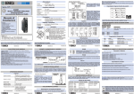
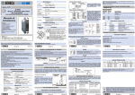
S SENECA 0..10 Vdc, 0..5 Vdc, Min. resistenza di carico: 2 kW. Uscita in corrente 0..20 mA, 4..20 mA, Max resistenza di carico: 500 W. Errore di ritrasmissione 0,1 % (del campo massimo). Tempo di risposta Deriva termica 2 s. (10%..90%) 100 ppm / K Alimentazione S203RC-D S203RC-D IT Uscita in tensione Analizzatore di rete trifase avanzato con display per sensori Rogowski Tensione 11 ..40 VDC oppure 19 ..28 VAC @ 50 ..60 Hz Assorbimento Max 2,5 W Categoria di installazione - per una misura corretta, il cavo conduttore deve essere posto in posizione centrale rispetto all’anello - per una misura più precisa, tarare il sensore Rogowski scrivendo il coefficiente di taratura nel registro Modbus corrispondente (vedere il manuale utente) o utilizzando il menu a display (vedere il manuale programmazione a display). Esempio: se il sensore è fornito con una caratteristica di 90 mV / 1000 A, sul registro taratura corrispondente alla fase in cui il sensore Rogowski è applicato, il valore da impostare è: 1000 / (90 · 10). NOTA SULLA PRECISIONE: lo S203RC-D è fornito al 0.5%, quindi indipendente dalla precisione del sensore Rogowski che il cliente desidera collegare. La precisione totale è la somma tra la precisione dell’S203RC-D e la precisione del sensore Rogowski collegato. III (fino a 300 V), II (fino a 600 V) Categoria SENSORE ROGOWSKI Condizioni ambientali Temperatura Umidità Temperatura di stoccaggio Manuale di Installazione -10 ..+65°C 30 ..90% a 40°C non condensante IP20 Connessioni Morsetti a vite, passo 5,08 / 7,5 mm V 34 105 x 89 x 60 mm Materiale plastico UL 94 VO, colore grigio EN61010-1/2001 (sicurezza). ITALIANO 3/8 SPECIFICHE TECNICHE Porte di comunicazione RS485 Baud rate: 1200..115200 baud. Protocollo Modbus RTU USB Ingresso mini-USB per programmazione (software Easy) Ingresso Frequenza di rete: 50 o 60 Hz. Voltmetro : 0,5 %. Classe / Prec. base (1) Amperometro : 0,5 %. Wattmetro : 0,5 %. Ingresso in tensione Fino a 600 Vac, frequenza 50 o 60 Hz Specifiche del sensore Segnale in uscita per ingresso in corrente S203RC-D: • 100 mV corrispondono a 1000 A @ 50 Hz (sinusoidale) Rogowski fornito da • 120 mV corrispondono a 1000 A @ 60 Hz (sinusoidale) Seneca e calibrato Massima corrente misurabile: 100 kA @ 50/60 Hz (accessorio Resistenza interna: 30 Ohm / 400 mm Precisione dopo calibrazione: ± 1 % (vedere capitolo RC-V400-100) «Sensore Rogowski») Linearità: ± 0.2 % (1) Le precisioni sono garantite nei seguenti range: Vrms: 40..600 Vac; Cosf>0,9 (escluso errore dovuto a sensori Rogowski esterni) Irms: 0,4-100% Corrente del Rogowski Uscita digitale per impulsi contatore energia Tipo Passivo (deve essere alimentata), non protetta dal corto circuito Portata 50 mA / 28 V ITALIANO 2/8 Significato dei LED Acceso fisso (VERDE) Indica la presenza dell’alimentazione. ERR Acceso fisso (GIALLO) Tensione misurata inferiore a 40 Vac su almeno una delle fasi attive. TX Lampeggiante (ROSSO) Lampeggiante (ROSSO) Indica la trasmissione di dati sulla porta di comunicazione RS485. Indica la ricezione di dati sulla porta di comunicazione RS485. Range di misura 0..600 Vac 0..1000 A (0..1000 * 600)W (0..1000 * 600)VAR (0..1000 * 600)VA 0..1 40..70 Hz INTERFACCIA SERIALE Per informazioni dettagliate sull’interfaccia seriale RS485 fare riferimento alla documentazione presente nel sito www.seneca.it, nella sezione Prodotti/Serie ZPC/MODBUS TUTORIAL. Segnalazione tramite LED Programmazione I parametri di comunicazione hanno i seguenti valori di default: baudrate=38400, parità nessuna, numero bit=8, bit stop=1. Questi valori possono essere modificati a display o attraverso protocollo Modbus. Per programmare il dispositivo, è possibile scaricare gratuitamente il software Easy Setup dal sito www.seneca.it. ITALIANO 5/8 MI003072-I 33 32 31 11 ÷ 40 VDC 19 ÷ 28 VAC 2.5 W 26 25 + - + - + - INGRESSO MONOFASE 13 14 15 16 17 18 A VG CONTENITORE E NUMERAZIONE MORSETTI 36 35 34 33 32 31 30 29 28 RS 485 ALIMENTAZIONE x N B A GND Non è presente isolamento tra RS485 e uscita analogica. 19 20 21 22 Rogowski’s coil TX ERR 13 14 15 16 17 18 19 20 21 22 A VG B C S SENECA S203RC-D RX PWR 10 11 12 13 14 15 16 17 18 ZL x PANNELLO FRONTALE A DISPLAY S203RC-D 13 14 15 16 17 18 19 20 21 22 A VG B NC A)MEASURE CONFIG x x ZL x Nota: Collegare lo schermo dei sensori Rogowski al negativo (-), ovvero indifferentemente in uno dei morsetti 14, 16, 18, 22. I morsetti 14, 16, 18 e 22 sono internamente connessi assieme. ESC OK MENÙ PROGRAMMAZIONE DEL DISPLAY Per informazioni dettagliate sulla programmazione del display e visualizzazione parametri, fare riferimento al manuale di programmazione, che può essere scaricato gratuitamente dal sito www.seneca.it. SENSORE ROGOWSKI Il sensore Rogowski (accessorio RC-V400-100) è un anello schermato progettato per misure di forme d’onda AC, DC impulsive o complesse. Per il suo corretto utilizzo, - avvolgere l’anello sul conduttore in modo che il simbolo a freccia riportato nell’anello sia orientato nel stesso verso della corrente del conduttore - assicurarsi che le connessioni siano effettuate correttamente: il filo di uscita bianco è il positivo (+), il filo marrone è il negativo (-). ITALIANO 4/8 22 21 20 19 x + - + - + - 4 FILI Trifase con Neutro Se necessario, per il d e b u g d e l l a comunicazione, e s t r a r r e i l coprimorsetti per poter osservare i LED. 26 25 ZL + - + - + - ARON Trifase senza Neutro ITALIANO 7/8 MI003072-I COLLEGAMENTI ELETTRICI Il modulo mette a disposizione, negli appositi registri MODBUS, i valori delle seguenti grandezze elettriche: Vrms, Irms, Watt, VAR, VA, Frequenza, Cosf e Energia Attiva. Nel caso di applicazione trifase per ciascuna delle grandezze sopracitate oltre al valore trifase (eccetto la frequenza) sono disponibili i valori corrispondenti a ciascuna delle tre fasi. Tali valori sono disponibili sia in formato floating point sia normalizzati (eccetto la Frequenza e l’Energia attiva) tra 0..+10000 (-10000 ..+10000 per VAR e Cosf). Il valore dell’energia viene mantenuto in memoria e nel caso la macchina si spenga viene tenuto l'ultimo valore prima dello spegnimento. Il modulo ritrasmette in uscita, come segnale in corrente o tensione, una grandezze a scelta tra: Vrms, Irms, Watt, cosF. Se l’applicazione è trifase lo strumento automaticamente trasmette il valore trifase della grandezza selezionata, ma tramite registro Modbus l’utente può personalizzare la ritrasmissione della grandezza su una delle tre fasi A, B e C. L’utente può impostare tramite registri MODBUS i valori MIN e MAX della grandezza in ingresso corrispondenti rispettivamente allo 0 % e al 100 % dell’uscita ritrasmessa. Ad esempio se il segnale ritrasmesso è in corrente 4..20 mA e la grandezza da ritrasmettere la tensione Vrms nel range 10..300 V (quindi MIN=10, MAX=300) avremo che se Vrms=10 V allora l’uscita analogica varrà 4 mA mentre se Vrms=300 V l’uscita ritrasmessa varrà 20 mA. Nei valori intermedi il comportamento è lineare. I valori dell’uscita analogica saturano a circa 11 V per le uscite in tensione e a circa 22 mA per le uscite in corrente (perché l’uscita ritrasmessa è limitata al 110 %). Se la frequenza di rete si discosta di quantità superiori ai 30 mHz dai valori nominali (50 o 60 Hz), è possibile compensare gli errori sulle misure di Potenza ed Energia, causati da queste fluttuazioni. Tale funzionalità è attivabile tramite registro MODBUS. Si evidenzia che le misure di Vrms e Irms non sono influenzate dalle sopracitate oscillazioni di frequenza. All'accensione vengono prelevati i coefficienti di taratura appropriati (dipendenti dalla scelta della frequenza 50 o 60 Hz). Tutte le impostazioni vengono caricate al reset. NOTA: in assenza di carico collegato all’S203RC-D, solo la tensione e la frequenza visualizzata (a display) hanno un valore valido. MI003072-I STATO PWR RX FILO MARRONE (-) Grandezze elettriche V rms I rms Potenza attiva Potenza reattiva Potenza apparente Cosf Frequenza LOGICA DI FUNZIONAMENTO CARATTERISTICHE GENERALI L’S203RC-D è un analizzatore di rete trifase completo con display, per utilizzo esclusivo con sensori Rogowski, adatto a range di tensione fino a 600 Vac (50 Hz o 60 Hz), e correnti massime di 1000 A connessi agli ingressi.Lo strumento è in grado di fornire tutte le seguenti grandezze elettriche: Vrms, Irms, Watt, VAR, VA, Frequenza, Cosf e Energia Attiva. Per le grandezze sopra elencate (tranne la frequenza) sono disponibili sia i valori di fase che il valore complessivo trifase. Tutti i valori possono essere acquisiti tramite comunicazione seriale sia in formato floating point sia normalizzate (eccetto frequenza e Energia Attiva).È anche possibile la ritrasmissione analogica di una qualsiasi delle grandezze Vrms,Irms,Watt e Cosf monofase, trifase, o su una fase a scelta (impostazione tramite display o registro MODBUS).Il modulo è caratterizzato da: Configurabilità della comunicazione via software. Comunicazione seriale RS485 con protocollo MODBUS-RTU, massimo 32 nodi. Alloggiato in contenitore DIN per rapido aggancio su guida DIN. Elevata precisione: classe 0,5 %. Protezione contro scariche ESD fino a 4 kV. Isolamento ingresso di misura: 4000 Vac rispetto a tutti gli altri circuiti. Isolamento tra comunicazione e alimentazione: 1500 Vac. Isolamento tra uscita analogica e alimentazione: 1500 Vac. Uscita analogica impostabile in tensione o corrente. Uscita digitale per contabilizzazione energia Ammessi tutti i tipi di inserzione: monofase, Aron, quattro fili. Possibilità di compensare gli errori dovuti alle variazioni di frequenza in ambienti in cui la frequenza di rete non sia stabile (fluttuazioni > 30 mHz). MI003072-I MI003072-I Uscita digitale LED SCHERMO Range di misura delle grandezze elettriche EN61000-6-4/2002 (emissione elettromagnetica, in ambiente industriale). EN61000-6-2/2006 (immunità elettromagnetica, in ambiente industriale). ITALIANO 1/8 GANCIO DI CHIUSURA E SIMBOLO DEL VERSO DELLA CORRENTE FILO BIANCO (+) 4000 Vac tra ingresso di misura e tutti gli altri circuiti 1500 Vac tra alimentazione e comunicazione 1500 Vac tra alimentazione e uscita ritrasmessa Questo documento è di proprietà SENECA srl. La duplicazione e la riproduzione sono vietate, se non autorizzate. Il contenuto della presente documentazione corrisponde ai prodotti e alle tecnologie descritte. I dati riportati potranno essere modificati o integrati per esigenze tecniche e/o commerciali. MI003072-I 29 30 LCD frontale 2 righe x 16 caratteri alfanumerici retroilluminato Normative Via Germania, 34 - 35127 - Z.I. CAMIN - PADOVA - ITALY Tel. +39.049.8705355 - 8705359 - Fax +39.049.8706287 Per i manuali e i software di configurazione, visitare il sito www.seneca.it 34 Segnalazione tramite LED Lo strumento è conforme alle seguenti normative: SENECA s.r.l. V R Verso della corrente nel conduttore Isolamenti Tensioni di isolamento Corrente Alim. Esterna (2) 36 USCITA DIGITALE Il modulo fornisce un’uscita digitale: ad ogni impulso corrisponde un certo numero di incrementi del conteggio di energia. Imax=V/R=50 mA, Vmax=28V. Per ulteriori informazioni, consultare il manuale di programmazione display. I Ingombri / contenitore / display Dimensioni Contenitore Display + Non è presente isolamento tra RS485 e uscita ritrasmessa. Connessioni Contenuti: - Caratteristiche Generali - Specifiche Tecniche - Logica di funzionamento - Sensore Rogowski - Grandezze elettriche - Collegamenti Elettrici - Segnalazione tramite LED - Interfaccia seriale - Contenitore e numerazione morsetti - Pannello frontale a display - Programmazione del display Corrente Impressa (1) 36 A 35 Tensione 35 CAVO CONDUTTORE DI FASE -20 ..+85°C Grado di Protezione USCITA ANALOGICA Il modulo fornisce un’uscita in tensione (0..10 Vdc) o corrente attiva o passiva (0..20 mA) programmabile. Per i collegamenti elettrici si raccomanda l’utilizzo di cavi schermati. + Uscita analogica Smaltimento dei rifiuti elettrici ed elettronici (applicabile nell’Unione Europea e negli altri paesi con raccolta differenziata). Il simbolo presente sul prodotto o sulla confezione indica che il prodotto non verrà trattato come rifiuto domestico. Sarà invece consegnato al centro di raccolta autorizzato per il riciclo dei rifiuti elettrici ed elettronici. Assicurandovi che il prodotto venga smaltito in modo adeguato, eviterete un potenziale impatto negativosull’ambiente e la salute umana, che potrebbe essere causato da una gestione non conforme dello smaltimento del prodotto. Il riciclaggio dei materiali contribuirà alla conservazione delle risorse naturali. Per ricevere ulteriori informazioni più dettagliate Vi invitiamo a contattare l’ufficio preposto nella Vostra città, il servizio per lo smaltimento dei rifiuti o il fornitore da cui avete acquistato il prodotto. MI003072-I ITALIANO 6/8 MI003072-I ITALIANO 8/8 S SENECA EN 0..10 Vdc, 0..5 Vdc, Min. load resistance: 2 kW. 0..20 mA, 4..20 mA, Max load resistance: 500 W. Current Output Transmission error Response time Thermal stability 0,1 % (max range). 2 s (10%..90%) 100 ppm / K Other Specifications S203RC-D S203RC-D Voltage Advanced Three-phase Network Analyzer with display for Rogowski’s sensor 11 ..40 VDC or 19 ..28 VAC @ 50 ..60 Hz Max 2,5 W Consumption Installation III (up to 300 V), II (up to 600 V) Installation category Environmental conditions - For a correct measurement, place the cable conductor in a central position with reference to the ring - For an more accurate measurement, calibrate the Rogowski’s coil: write the calibration coefficient to the corresponding Modbus register (refer to the user manual) or set it using the menu on the display (see display programming manual). Example: if the Rogowski’s coil feature is 90 mV / 1000 A, set the tarature register (corresponding to the phase where the Rogowski’s coil is applied) with the value: 1000 / (90 · 10). NOTE ABOUT ACCURACY: S203RC-D is provided at 0.5%, so regardless of the accuracy of the Rogowski’s coil that the customer wants to connect. Global accuracy is the sum between the S203RC-D accuracy and Rogowski’s coil accuracy connected. ROGOWSKI’s COIL Temperature -10 ..+65°C Humidity 30 ..90% Storage temperature -20 ..+85°C International IP20 protection Installation Manual ANALOG OUTPUT The module provides a programmable, analog output in voltage (0..10 Vdc) or active and passive current (0..20 mA). We recommend using shielded cables for the electric connections. External power supply Voltage current (2) Active current (1) 36 35 36 + A V 34 34 35 + Analog Output Voltage Output There is no insulation between RS485 and the analog output. DIGITAL OUTPUT The module has a digital output: each pulse corresponds to a given number of increments about to the energy counter. Imax=V/R=50 mA, Vmax=28V. For more informations, see the display settings manual. I V R PHASE CONDUCTOR 29 Digital output 30 Connections Contents: Contents: -- General General Specifications specifications -- Technical Technical Specifications features -- Installation FunctioningRules -- Electrical connections Rogowski’s coil -- Modbus Electricalconnection quantities rules -- DIP-switches settings Electrical connections -- Digital inputs LEDs signallings -- Leds SerialSignallings interface -- Factory Settings Case and screw terminal numbers Screw terminals, 5,08 / 7,5 pitch Connections Dimensions / case / display CLOSURE HOOK AND SYMBOL OF CURRENT DIRECTION Current direction in the conductor Dimensions 105 x 89 x 60 mm Case Plastic UL 94 VO, grey color. Display Front LCD 2 lines x 16 characters alphanumeric (backlighted) Isolations WHITE WIRE (+) 4000 Vac between the input and all the other circuits. 1500 Vac between power supply and communication. 1500 Vac between power supply and analog output. Insulation voltage - Front panel - Display programming Standards Via Germania, 34 - 35127 - Z.I. CAMIN - PADOVA - ITALY Tel. +39.049.8705355 - 8705359 - Fax +39.049.8706287 For manual and configuration softwares, see www.seneca.it EN61000-6-4/2002 (electromagnetic emission, industrial environment). EN61000-6-2/2006 (electromagnetic immunity, industrial environment). This document is property of SENECA srl. Duplication and reprodution are forbidden, if not authorized. Contents of the present documentation refers to products and technologies described in it. All technical data contained in the document may be modified without prior notice Content of this documentation is subject to periodical revision. MI003072-E ENGLISH 1/8 TECHNICAL FEATURES Communication port RS485 Baud rate: 1200..115200 baud. Protocol: Modbus RTU USB Mini-USB, for programming (software Easy) Class/Base Precision (1) Network Frequency: 50 or 60 Hz.Voltmeter : 0,5 %. Amperometer : 0,5 %. Wattmeter : 0,5 %. Input Up to 600 Vac, frequency 50 or 60 Hz Voltage input Output signal for S203RC-D current input: Rogowski’s coil • 100 mV correspond to 1000 A @ 50 Hz (sinusoidal) features, supplied by • 120 mV correspond to 1000 A @ 60 Hz (sinusoidal) Seneca and calibrated Max measurable current: 100 kA @ 50/60 Hz (accessory Internal resistance: 30 Ohm / 400 mm Accuracy after calibration: ± 1 % (see the chapter RC-V400-100) «Rogowski’s coil») Linearity: ± 0.2 % (1) Precisions are given in the following range: Vrms: 40..600 Vac; Cosf>0,9 (without error due to external Rogowski’s coil) Irms: 0,4-100% Iprimary of Rogowski’s coil Digital output for energy counter Type Passive (it has to be powered on), no protection for short circuit Range 50 mA / 28 V ENGLISH 2/8 LEDs signallings PWR ON (GREEN) The module is power on ERR ON (YELLOW) At least one of the active phases’ voltage is less than 40 Vac TX Blinking (RED) Blinking (RED) Data are being transmitted through the RS485 comm. port Data are being received through the RS485 comm. port RX ENGLISH 3/8 SERIAL INTERFACE Measurement Range 0..600 Vac 0..1000 A (0..1000 * 600)W (0..1000 * 600)VAR (0..1000 * 600)VA 0..1 40..70 Hz Electrical Quantity V rms I rms Active Power Reactive Power Apparent Power Cosf Frequency For detailed information on RS485 serial interface, consult the documentation provided by the website www.seneca.it, in the section Prodotti/Serie Z-PC/MODBUS TUTORIAL. Segnalazione tramite LED Programming The communication parameters have the following default values:: baudrate=38400, no parity, bit number=8, bit stop=1. These values can be modified by display or Modbus protocol. To program the device, download the free software Easy Setup from the website www.seneca.it. ENGLISH 5/8 MI003072-E OPERATING LOGIC GENERAL SPECIFICATIONS Model S203RC-D is a complete three-phase network analyzer, with display, that can be use only with Rogowski’s coil: up to 600Vac voltage range, max current equal to 1000 A connected to the inputs.The instrument provides all the following electrical measurable quantities: Vrms, Irms, Watt, VAR, VA, Frequency, Cosf and Active Energy. All measurements given above (except frequency) are available both single-phase and threephase.Measurements are read through serial communication both in floating point and normalized format (except Frequency and Active Energy).It is possible the analog retransmission of any Vrms, Irms, Watt and Cosf quantity either single phase or threephase, or any phase chosen (by specific display or MODBUS registry). The module is also distinguished by: Communication configurability through software. RS485 serial communication with MODBUS-RTU protocol, maximum 32 nodes. Easy-wiring of power supply and serial bus by means of the bus housed in the DIN rail. High precision: 0,5 % class. Protection against ESD discharge up to 4 kV. Measure input insulation: 4000 Vac towards all the other circuits. Insulation between communication and power supply: 1500Vac. Insulation between retransmitted output and power supply: 1500Vac. Analog output signal settable in voltage or current. Digital output for energy counter All kind of insertion possible: single phase, Aron, four wires Possibility to compensate errors caused by frequency change in places where network frequency is not stable (frequency changes > 30 mHz). MI003072-E EN61010-1/2001 (safety) MI003072-E STATUS Retransmission range Reference standards : SENECA s.r.l. SHIELD BROWN WIRE (-) LEDs signallings Segnalazione tramite LED LED CASE AND SCREW TERMINAL NUMBERS ELECTRIC CONNECTIONS The module measures the following electrical quantities: Vrms, Irms, Watt, VAR, VA, Frequency, Cosf and Active Energy, and provides the values in the corresponding MODBUS registers. In three-phase environments, measurements given above corresponding to any phase are available, other than the three-phase value (except the frequency). These measurements are rendered in both floating point and normalized format (except Frequency and Active energy) between 0..+10000 (-10000 ..+10000 for VAR e Cosf). Active energy value is stored in memory and when the instrument is switched off, the last value before switching is kept in memory. The module output can transmit one of the following quantities: Vrms, Irms, Watt, cosF as either a current or voltage value. If the instrument is set for three-phase measurements, it transmits automatically the three-phase value of the selected measurement. However, via MODBUS register, the user can choose to transmit the measurement corresponding to any phase: A, B, C. The user can set through MODBUS the values MIN and MAX of the measurement to transmit corresponding to 0% and 100% of the analog output. For example, if the signal is transmitted as current 4..20 mA and the quantity to transmit is voltage Vrms in the 10..300 V range, (therefore MIN=10, MAX=300), then if Vrms measured is 10V, analog output will be 4mA, while if Vrms=300V output will be 20mA. In the intermediate points the behaviour is linear. The analog output values saturate at approximately 11 V for voltage output and at 22mA for current output (analog output clamped at 110 %). If network frequency oscillates more than 30 mHz from rated values (50 o 60 Hz), it’s possibile to compensate errors on measurements of Power and Energy caused by these variations. This option is selectable via MODBUS register. Vrms and Irms measurements are not influenced by these variations. When the module is switched on, the appropriate setting coefficients are measured (depending on the choice of 50 or 60 Hz frequency). All the settings made will be automatically loaded when the module is reset. NOTE: without load connected to the S203RC-D, only the (displayed) voltage and frequency assume a corrected value. ENGLISH 7/8 MI003072-E 36 35 34 33 32 31 30 29 28 RS 485 POWER SUPPLY For communication debugging, remove the terminals cover to see the internal LEDs. B 33 11 ÷ 40 VDC A 32 19 ÷ 28 VAC 2.5 W GND 31 There is no insulation between RS485 and the analog output 26 25 + - + - + - INPUT SINGLE PHASE 13 14 15 16 17 18 A VG x N ARON Three-Phase without Neutral Rogowski’s coil 26 25 22 21 20 19 S SENECA S203RC-D 19 20 21 22 TX ERR ZL RX PWR + - + - + - 13 14 15 16 17 18 19 20 21 22 A VG B C x 10 11 12 13 14 15 16 17 18 ZL FRONT PANEL x S203RC-D + - + - + - 4 WIRES Three-Phase with Neutral 13 14 15 16 17 18 19 20 21 22 A VG B NC A)MEASURE CONFIG x x ZL x ESC Note: Connect the shield of the Rogowski’s coil at negative (-), so one of the terminals 14, 16, 18, 22. OK MENÙ Terminals 14, 16 18 and 22 are internally connected. ROGOWSKI’S COIL DISPLAY PROGRAMMING For detailed information on display programming, consult the documentation provided by the website www.seneca.it. Rogowski’s coil (accessory RC-V400-100) have been designed for accurate nonintrusive measurement of AC, pulsed DC or complex waveforms. To use in an appropriate way, - wrap the ring on the conductor so that the arrow symbol (stamped in the ring) is oriented in the same direction of the current in the conductor - make sure that the connections are performed properly: the white output wire is positive (+), the brown wire is the negative (-). MI003072-E ENGLISH 4/8 Disposal of Electrical & Electronic Equipment (Applicable throughout the European Union and other European countries with separate collections programs). This symbol, found on your producr or on its packaging, indicates that this product should not be treated as household waste when you wish to dispose of it. Instead, it should be handed over to an applicable collection point for the recycling of electrical & electronic equipment. By ensuring this product is didposed of correctly, you will help prevent potential negative consequences to the environment and human health, which could otherwise be caused by inappropriate disposal of this product. The recycling of materials will help to conserve natural resources. For more detailed information about the recycling of the product, please contact your local city office, waste disposal service of the retail store where you purchased this product. MI003072-E ENGLISH 6/8 MI003072-E ENGLISH 8/8