1
Composantes Bluetooth selon IEEE 802.15.1
Español
Montaje
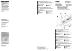
Atornille el módulo sobre una superficie de
montaje plana con dos tornillos (p. ej. con
tornillos cilíndricos DIN 84-M3 x 25-8.8).
La distancia entre agujeros puede verla en
el dibujo.
Parámetros IP por defecto
Consignes de sécurité et avertissements
Français
1
Dirección IP por defecto
10.0.0.100
Máscara de sub-red por defecto
255.255.0.0
Observer les mesures de précaution nécessaires lors du maniement des
composants sensibles aux décharges électrostatiques
(EN 61340-5-1 et EN 61340-5-2 ainsi que CEI 61340-5-1 et CEI 61340-52).
Limitations d'utilisation selon la recommandation ERC
70-03 /avril 2004 pour la France : puissance d'émission maximale à l'extérieur 10 mW (10 dBm). Tenir compte des caractéristiques de l'antenne !
Pour de plus amples informations techniques, voir le manuel d'utilisation sous
www.download.phoenixcontact.fr.
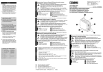
1 Alésages de fixation
4 Raccordement au réseau
2 Antenne
5 Interface série
3 Raccordement de la tension
6 Voyants de diagnostic et d'état
d'alimentation
AUTOMATIONWORX
FL BLUETOOTH AP
DE
EN
FR
IT
ES
PHOENIX CONTACT GmbH & Co. KG
32823 Blomberg, Germany
Phone
+49-(0)5235-3-00
Fax
+49-(0)5235-3-41200
www.phoenixcontact.com
Art.-Nr. 27 37 99 9
Einbauanweisung für den Elektroinstallateur
Installation notes for electrical personnel
Instructions d’installation pour l’électricien
Istruzioni di installazione per l’elettricista
Instrucciones de montaje para el instalador eléctrico
2
1
Componenti Bluetooth secondo IEEE 802.15.1
3
5
6
7
Asignación del conector hembra RJ45
(Ethernet)
Pin 1
TD+
Pin 2
TDPin 3
RD+
Pin 6
RDPin 4, 5, 7 y 8
Reservado
Carcasa
Tierra funcional
Asignación del conector hembra D-SUB
(sólo para actualización del firmware)
Pin 1
n.c.
Pin 2
RD
Pin 3
TD
Pin 4
DTR
Pin 5
GND
Pin 6
DSR
Pin 7
RTS
Pin 8
CTS
Pin 9
n.c.
FL BLUETOOTH AP
Bluetooth Access Point
Ord No.: 27 37 999
6
5
Componentes Bluetooth según IEEE 802.15.1
Indicaciones y advertencias de seguridad
Bluetooth Access Point nach IEEE 802.15.1
¡Observe las medidas preventivas necesarias al manipular elementos
expuestos a peligro de descarga electrostática (EN 61340-5-1 y
EN 61340-5-2 así como IEC 61340-5-1 y IEC 61340-5-2)!
Limitaciones de utilización según Recomendación ERC
70-03 /Abril 2004 para Francia: máxima potencia de emisión de 10 mW (10
dBm) en caso de montarse en el exterior; tenga en cuenta los datos de la
antena.
Encontrará más información técnica en el manual de usuario que hallará en
www.download.phoenixcontact.es.
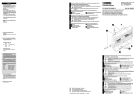
1 Agujeros de fijación
4 Conexión a la red
2 Antena
5 Interfaz serie
3 Conexión para tensión de
6 Indicaciones de diagnóstico y
alimentación
estado
Sicherheits- und Warnhinweise
Beachten Sie die notwendigen Vorsichtsmaßnahmen bei der Handhabung
elektrostatisch gefährdeter Bauelemente (EN 61340-5-1 und
EN 61340-5-2)!
Nutzungseinschränkungen gemäß ERC Recommendation
70-03 / April 2004 für Frankreich: außerhalb von Gebäuden maximale
Sendeleistung 10 mW (10 dBm); Antennendaten beachten!
Weiterführende technische Informationen finden Sie im Anwenderhandbuch unter
www.download.phoenixcontact.de.
1 Befestigungslöcher
4 Netzwerkanschluss
2 Antenne
5 Serielle Schnittstelle
3 Versorgungsspannungsanschluss 6 Status- und Diagnose-Anzeigen
Bluetooth component according to IEEE 802.15.1
Safety and warning instructions
Dimensiones de la carcasa
Véase la figura.
La profundidad de la carcasa es 26 mm.
¡Atención!
El sistema de radioenlace tiene que
usarse únicamente en combinación con
los accesorios que ofrece Phoenix Contact. ¡La utilización de otros componentes accesorios puede hacer que se
anule la licencia de uso!
Restablecer ajustes de fábrica
Desenchufe el dispositivo de la
alimentación eléctrica.
Una el pin 2 y el pin 3 de la interfaz serie con
un puente de cable.
Reinicie el dispositivo.
Tras unos 5 s. retire el puente de cable.
4
LAN
Serial
Bluetooth
Deutsch
4
Nel maneggiare elementi a rischio di scariche elettrostatiche, osservare le
necessarie misure di sicurezza (EN 61340-5-1 e EN 61340-5-2,
nonché IEC 61340-5-1 e IEC 61340-5-2)!
Limitazioni d'uso in conformità alla raccomandazione ERC
70-03 /aprile 2004 per la Francia: all'esterno di edifici, potenza di trasmissione massima 10 mW (10 dBm); tenere presente i dati dell'antenna!
Per ulteriori informazioni tecniche consultare il manuale utente all'indirizzo
www.download.phoenixcontact.it.
1 Fori di fissaggio
4 Connessione alla rete
2 Antenna
5 Interfaccia seriale
3 Collegamento della tensione di
6 LED di stato e di diagnosi
alimentazione
English
3
Conexión de la tensión de alimentación
Alimente el dispositivo a 24 V CC.
Alimentación a 24 V CC
Borne 1
0V
Borne 2
24 V CC
Indicaciones de diagnóstico y estado
LED 1 (parpadeante, azul/azul) Hay otro dispositivo conectado a Access
Point (azul)
- Transmisión de datos en el Bluetooth
(parpadea a 1 Hz)
- Estableciendo conexión Bluetooth
(parpadea a 4 Hz)
LED 2 (verde) - Enlace Ethernet
LED 2 (amarillo) - Comunicación Ethernet
LED 3 (amarillo) - Transmisión de
datos serie
Español
2
Italiano
Avvertenze sulla sicurezza e sui pericoli
DE
EN
FR
IT
ES
Technische Änderungen vorbehalten!
Technical modifications reserved!
Sous réserve de modifications techniques.
Con riserva di modifiche tecniche!
¡Reservado el derecho a las modificaciones técnicas!
© PHOENIX CONTACT 06/2008
MNR 90 31 28 5 - 04
726804
Observe the necessary safety precautions when handling components that
are vulnerable to electrostatics (EN 61340-5-1 and EN 61340-5-2, as well
as IEC 61340-5-1 and IEC 61340-5-2)!
Restrictions of use as per ERC Recommendation
70-03 / April 2004 for France: Outside of buildings the max. transmission
power is 10 mW (10 dBm), pay attention to the aerial data!
CAUTION: DO NOT CONNECT DIRECTLY TO LINE VOLTAGE. LINE
VOLTAGE MUST BE SUPPLIED BY A SUITABLE, APPROVED
ISOLATING TRANSFORMER HAVING SHORT CIRCUIT CAPACITY
NOT EXCEEDING 100 V-A MAXIMUM.
Wiring Terminals marked to indicate proper connections for the input power, output
power, and control circuits.
Field Wiring terminals to use Copper Conductors only, wire size AWG 14, minimum
temperature rating 60ºC.
Use a torque value of minimum 0.22 Nm to fasten the power connector.
This equipment is suitable for use in Class 1, Division 2, Groups A, B, C and D OR
nonhazardous locations only.
Open Type Device – This device is to be mounted into an enclosure suitable for the
location where it is installed.
Further technical information can be found in the user manual, at
www.download.phoenixcontact.com.
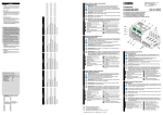
1 Mounting holes
4 Network connection
2 Aerial
5 Serial interface
3 Supply voltage connection
6 Status and diagnostic indicators
Deutsch
1
42 mm
1.654 in.
21 mm
0.827 in.
1
Default IP-Parameter
42 mm
1.654 in.
21 mm
0.827 in.
LAN
Serial
Bluetooth
5 mm
0.197 in.
5 mm
0.197 in.
70 mm
2.756 in.
2
3
- +
24 V DC
FL BLUETOOTH AP
Bluetooth Access Point
Ord No.: 27 37 999
1
2
3
3
LAN
Serial
Bluetooth
4
5
R J 4 5
P in 8
re s .
P in 7
re s .
P in 6
R D -
P in 5
re s .
5
6
Frontseite
Frontside
Partie front.
Lato front.
Cara frontal
P in 4
re s .
1
n. c.
4
DTR
7
RTS
P in 3
R D +
2
RD
5
GND
8
CTS
P in 2
T D -
3
TD
6
DSR
9
n. c.
P in 1
T D +
5
6
7
30 mm
1.181 in.
63 mm
2.480 in.
1
6
4
6
English
1
Installation
Screw the module tightly down onto a flat
surface by using two screws (e. g. with
cylinder head screw DIN 84-M3 x 25-8.8).
See the illustration for the drill hole distance.
10 mm
0.394 in.
Montage
Visser le module sur une surface de montage
plane à l'aide de deux vis (par ex. deux vis à
tête cylindrique DIN 84-M3 x 25-8.8).
Italiano
1
L'écartement des perçages est indiqué dans le
dessin ci-contre.
Montaggio
Fissare il modulo avvitandolo su una superficie di montaggio piana con due viti
(ad es. con viti a testa cilindrica
DIN 84-M3 x 25-8.8).
Riferirsi al disegno per la distanza e le dimensioni dei fori.
Default IP parameters
Paramètres IP par défaut
Default IP-Adresse
10.0.0.100
Default IP address
10.0.0.100
Adresse IP par défaut
10.0.0.100
Indirizzo IP di default
10.0.0.100
Default Subnetzmaske
255.255.0.0
Default subnet mask
255.255.0.0
Masque de sous-réseau par défaut
255.255.0.0
Maschera subnet di default
255.255.0.0
2
Belegung der RJ45-Buchse (Ethernet)
Pin 1
TD+
Pin 2
TDPin 3
RD+
Pin 6
RDPin 4, 5, 7 u. 8 reserviert
Gehäuse
Funktionserde
Belegung der D-SUB-Buchse
Pin 1
n.c.
Pin 2
RD
Pin 3
TD
Pin 4
DTR
Pin 5
GND
Pin 6
DSR
Pin 7
RTS
Pin 8
CTS
Pin 9
n.c.
4
Gehäusemaße
Siehe Bild.
Die Gehäusetiefe beträgt 26 mm.
6
3
5
Achtung!
Der Betrieb des Funksystems ist nur
unter Verwendung des bei Phoenix
Contact erhältlichen Zubehörs zulässig.
Der Einsatz von anderen
Zubehörkomponenten kann zum
Erlöschen der Betriebsgenehmigung
führen!
FL BLUETOOTH AP
Bluetooth Access Point
Ord No.: 27 37 999
Anschluss der Versorgungsspannung
Speisen Sie das Gerät mit 24 V DC .
Versorgung mit 24 V DC
Klemme 1
0V
Klemme 2
24 V DC
Status- und Diagnose-Anzeigen
LED 1 (blau/blau-blinkend) Weiteres Gerät mit Access Point
verbunden (blau)
- Bluetooth-Datenübertragung
(blinkend 1 Hz)
- Bluetooth-Verbindungsaufbau
(blinkend 4 Hz)
LED 2 (grün) - Ethernet-Link
LED 2 (gelb) - Ethernet-Kommunikation
LED 3 (gelb) - Serielle Datenübertragung
LAN
Serial
Connecting the supply voltage
Supply the device with 24 V DC
Supply with 24 V DC
Terminal 1
0V
Terminal 2
24 V DC
Status and diagnostic indicators
LED 1 (blue/blue flashing) Further device connected with Access
Point (blue)
- Bluetooth data transmission
(flashing 1 Hz)
- Bluetooth connection establishment
(flashing 4 Hz)
LED 2 (green) - Ethernet link
LED 2 (yellow) - Ethernet communication
LED 3 (yellow) - Serial data transmission
2
Assignment of the RJ45 female connector (Ethernet)
Pin 1
TD+
Pin 2
TDPin 3
RD+
Pin 6
RDPin 4, 5, 7 and 8 Reserved
Housing
Functional earth ground
Assignment of the D-SUB female
connector
Pin 1
n.c.
Pin 2
RD
Pin 3
TD
Pin 4
DTR
Pin 5
GND
Pin 6
DSR
Pin 7
RTS
Pin 8
CTS
Pin 9
n.c.
4
Housing dimensions
See illustration.
The depth of the housing is 26 mm.
6
7
Bluetooth
80 mm
3.150 in.
Rücksetzen auf Werkseinstellungen
Trennen Sie das Gerät von der
Versorgungsspannung.
Verbinden Sie Pin 2 und Pin 3 der seriellen
Schnittstelle mit einer Drahtbrücke.
Starten Sie das Gerät neu.
Entfernen Sie nach ca. fünf Sekunden die
Drahtbrücke.
3
5
Attention!
The operation of the radio system is permitted only when using accessories
available from Phoenix Contact. When
other accessory components are used,
this can lead to a cancellation of the operation permit.
72810000
726804
Français
1
Parametri IP di default
FL BLUETOOTH AP
Bluetooth Access Point
Ord No.: 27 37 999
2
Montage
Schrauben Sie das Modul auf einer planen
Montagefläche mit zwei Schrauben
(z. B. mit Zylinderschrauben
DIN 84-M3 x 25-8.8) fest.
Den Bohrlochabstand können Sie der
Zeichnung entnehmen.
7
2
Affectation du connecteur femelle RJ45
(Ethernet)
Broche 1
TD+
Broche 2
TDBroche 3
RD+
Broche 6
RDBroches 4, 5, 7 et 8 Réservées
Boîtier
Terre de
fonctionnement
Affectation du connecteur femelle SUB-D
(mise à jour firmware uniquement)
Broche 1
n.c.
Broche 2
RD
Broche 3
TD
Broche 4
DTR
Broche 5
GND
Broche 6
DSR
Broche 7
RTS
Broche 8
CTS
Broche 9
n.c.
4
Dimensions du boîtier
Voir figure.
La profondeur du boîtier est de 26 mm.
6
3
5
Retour aux réglages d'usine
Déconnecter le dispositif de la tension
d'alimentation.
Raccorder les broches 2 et 3 de l'interface
série avec un pont à fil.
Redémarrer le dispositif.
Après env. cinq secondes, retirer le pont à fil.
Collegamento della tensione di alimentazione
Alimentare il dispositivo con 24 V DC.
Alimentazione con 24 V DC
Morsetto 1
0V
Morsetto 2
24 V DC
LED di stato e di diagnosi
LED 1 (blu/blu lampeggiante) ulteriore dispositivo collegato all'Access
Point (blu)
- trasmissione dati Bluetooth
(lampeggiante, freq. 1 Hz)
- creazione del collegamento Bluetooth
(lampeggiante, freq. 4 Hz)
LED 2 (verde) - collegamento Ethernet
LED 2 (giallo) - comunicazione Ethernet
LED 3 (giallo) - Trasmissione dati seriale
Assegnamento del connettore femmina RJ45 (Ethernet)
Pin 1
TD+
Pin 2
TDPin 3
RD+
Pin 6
RDPin 4, 5, 7 e 8
Riservati
Custodia
Rerra funzionale
Assegnamento del connettore
femmina D-SUB
(solo per l'aggiornamento del firmware)
Pin 1
n.c.
Pin 2
RD
Pin 3
TD
Pin 4
DTR
Pin 5
GND
Pin 6
DSR
Pin 7
RTS
Pin 8
CTS
Pin 9
n.c.
Ingombro della custodia
Vedere figura.
Profondità della custodia: 26 mm.
Attenzione!
L'uso del sistema radio è ammesso
soltanto utilizzando gli accessori disponibili presso Phoenix Contact.
L'impiego di altri accessori può provocare l'annullamento del permesso di
utilizzo!
Attention !
L'utilisation du système radio n'est autorisé
qu'avec les accessoires disponibles
auprès de Phoenix Contact. L'emploi
d'autres accessoires peut entraîner une
annulation de l'autorisation d'exploitation.
7
Resetting to factory default
Disconnect the supply voltage.
Use a jumper wire to connect pins 2 and 3 of
the serial interface.
Restart the device.
Remove the jumper wire after approx. five
seconds.
Raccordement de la tension
d'alimentation
Alimenter l'appareil avec une tension de
24 V DC.
Alimentation en tension 24 V DC
Borne 1
0V
Borne 2
24 V DC
Voyants de diagnostic et d'état
DEL 1 (bleu/bleu clignotante) appareil supplémentaire relié par
point d'accès (bleu)
- transmission de données Bluetooth
(clignote 1 Hz)
- établissement de la liaison Bluetooth
(clignote 4 Hz)
DEL 2 (verte) - liaison Ethernet
DEL 2 (jaune) - communication Ethernet
DEL 3 (jaune) - Transmission de
données série
7
Reset delle impostazioni di fabbrica
Scollegare il dispositivo dalla tensione di
alimentazione.
Collegare il pin 2 e il pin 3 dell'interfaccia
seriale con un ponticello a cavo.
Riavviare il dispositivo.
Dopo circa cinque secondi rimuovere il
ponticello a cavo.