1
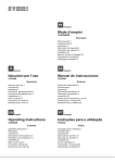
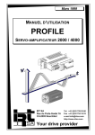
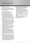
ESPAÑOL
ITALIANO
Panel táctil
Touch Panel
FRANÇAIS
Panneau à écran tactile
1. Advertencias de seguridad
1. Indicazioni di sicurezza
1. Consignes de sécurité
ENGLISH
SÜTRON electronic GmbH
Kurze Str. 29, 70794 Filderstadt, Germany
Fax +49-(0)711-7709860, Phone +49-(0)711-770980
80860.130
DEUTSCH
Touch panel
Touch Panel
1. Safety notes
1. Sicherheitshinweise
www.suetron.de
PELIGRO: tensión con peligro de electrocución
En las instalaciones eléctricas pueden aparecer tensiones
peligrosas para las personas. Existe peligro de
electrocución en caso de contacto con partes conductoras
de tensión.
IMPORTANTE
¡Observe las medidas preventivas necesarias al manipular
elementos expuestos a peligro de descarga electrostática
(EN 61340-5-1 y IEC 61340-5-1)!
Tenga también siempre presentes las informaciones
adicionales del manual de usuario que se encuentran en
www.suetron.de/en/manual.
2. Montaje (Fig. 2)
ATENCIÓN: daños
Para garantizar una buena circulación de aire, asegúrese
de dejar espacio libre alrededor del dispositivo de 30 mm
como mínimo durante el montaje.
ATENCIÓN: daños
Si monta el dispositivo horizontalmente, tenga en cuenta
que las fuentes de calor adicionales por debajo de este
pueden provocar un sobrecalentamiento.
¡Garantice que haya suficiente disipación del calor!
Tenga en cuenta el margen de temperatura admisible para
el funcionamiento del dispositivo que se indica en el
apartado de datos técnicos del manual de usuario.
ATENCIÓN: daños
Para garantizar el grado de protección especificado en los
datos técnicos, asegúrese sin falta de que la junta apoye
plana en la superficie de montaje y que los pasadores
roscados de las presillas de montaje se aprieten de forma
pareja con un par de apriete de máximo 1 Nm.
El dispositivo permite un montaje rápido y fácil desde su cara
trasera.
Para realizar un montaje correcto, se admiten grosores de pared
de 1 hasta 6 mm.
Tenga en cuenta las especificaciones para el corte de montaje
en la siguiente tabla.
Dispositivo
TP057ZTV /
TP057GTV
TP070ZTW /
TP070GTW
TP090ZTW /
TP090GTW
TP105ZTS /
TP105GTS
TP121ZTS /
TP121GTS
TP121ZTM /
TP121GTM
TP150ZTX /
TP150GTX
TP154ZTM /
TP154GTM
Corte de montaje (altura x anchura)
118 mm x 160 mm
139 mm x 195 mm
164 mm x 252 mm
212 mm x 287 mm
243,5 mm x 315 mm
217 mm x 322 mm
302 mm x 373 mm
273 mm x 396 mm
• Realice el corte de montaje acorde al tamaño del dispositivo a
instalar en la carcasa.
• Deslice el dispositivo por delante a través del corte de montaje.
• Coloque las presillas de montaje en las escotaduras previstas
para ello (1).
• Tire de las presillas de montaje hacia abajo hasta que
encastren (2).
• Fije el dispositivo con los pasadores roscados (3).
PERICOLO: Tensione di contatto pericolosa
Negli impianti elettrici possono prodursi tensioni
pericolose per le persone. In caso di contatto con parti
sotto tensione sussiste il pericolo di scossa elettrica!
DANGER : Tension de contact dangereuse
Des tensions dangereuses pour les personnes peuvent
exister dans les installations électriques. Le contact avec
les pièces sous tension présente un risque d'électrocution!
DANGER: Dangerous contact voltage
In electrical systems, hazardous voltages may occur
posing a danger to humans. There is a risk of electric
shock when touching live parts.
IMPORTANTE
Nel maneggiare elementi a rischio di scariche
elettrostatiche, osservare le necessarie misure di
sicurezza (EN 61340-5-1 e IEC 61340-5-1)!
IMPORTANT
Observer les mesures de précaution nécessaires lors du
maniement des composants sensibles aux décharges
électrostatiques (EN 61340-5-1, CEI 61340-5-1).
NOTE
Observe the necessary safety precautions when handling
components that are vulnerable to electrostatic discharge
(EN 61340-5-1 and IEC 61340-5-1)!
Attenersi anche alle informazioni aggiuntive riportate nel
manuale per l'uso scaricabile dal sito www.suetron.de/en/
manual.
Tenez également compte des informations
complémentaires du manuel d'utilisation via
www.suetron.de/en/manual.
For more detailed information, please also refer to the user
manual which can be downloaded at www.suetron.de/en/
manual.
2. Montaggio (Fig. 2)
2. Montage (Fig. 2)
IMPORTANTE: danni materiali
Al momento del montaggio, tenere in considerazione uno
spazio libero intorno al dispositivo di almeno 30 mm per
garantire una circolazione d'aria sufficiente.
IMPORTANT : Dommage
Lors du montage, prévoir un espace d'au moins 30 mm
autour de l'appareil pour garantir une circulation suffisante
de l'air.
IMPORTANTE: danni materiali
In caso di montaggio orizzontale del dispositivo, tenere
presente che eventuali fonti di calore aggiuntive al di sotto
del dispositivo possono provocare un ristagno di calore.
Garantire una dissipazione di calore sufficiente!
Tenere presente l'intervallo di temperatura ammesso per
l'esercizio del dispositivo indicato nei dati tecnici del
manuale utente!
IMPORTANT : Dommage
Lorsque l'appareil est monté à l'horizontale, tenir compte
du fait que la présence de sources de chaleur
supplémentaires sous celui-ci peut conduire à une
accumulation de la chaleur.
Faire en sorte de garantir une dissipation suffisante de la
chaleur.
Respecter la plage de température de fonctionnement
admissible de l'appareil indiquée dans les caractéristiques
techniques figurant dans le manuel d'utilisation.
IMPORTANTE: danni materiali
Per garantire il grado di protezione indicato nei dati tecnici,
assicurarsi in ogni caso che la guarnizione sia disposta in
piano sulla superficie di montaggio e le viti senza testa
delle graffe di montaggio siano serrate in modo uniforme
con una coppia di serraggio massima di 1 Nm.
Il dispositivo consente un montaggio semplice e rapido dal lato
posteriore del dispositivo.
Per un montaggio corretto sono ammesse pareti con uno
spessore variabile da 1 mm fino a 6 mm.
Rispettare le indicazioni sulla dima di foratura nella tabella
seguente.
Apparecchio
TP057ZTV /
TP057GTV
TP070ZTW /
TP070GTW
TP090ZTW /
TP090GTW
TP105ZTS /
TP105GTS
TP121ZTS /
TP121GTS
TP121ZTM /
TP121GTM
TP150ZTX /
TP150GTX
TP154ZTM /
TP154GTM
Dima di foratura (altezza x larghezza)
118 mm x 160 mm
139 mm x 195 mm
164 mm x 252 mm
212 mm x 287 mm
243,5 mm x 315 mm
217 mm x 322 mm
302 mm x 373 mm
273 mm x 396 mm
• Praticare nella custodia una dima di foratura corrispondente
alle dimensioni del dispositivo da installare.
• Inserire il dispositivo frontalmente attraverso la dima di
foratura.
• Inserire le graffe di montaggio nelle apposite cavità (1).
• Tirare le graffe di montaggio verso il basso fino all'innesto (2).
• Fissare il dispositivo con le viti senza testa (3).
IMPORTANT : Dommage
Pour garantir le respect de l'indice de protection indiqué
dans les caractéristiques techniques, veiller
impérativement à ce que le joint soit bien à plat sur la
surface de montage et à ce que les vis sans tête des clips
de montage soient serrées de manière régulière à un
couple maximum de 1 Nm.
L'appareil peut être monté rapidement et simplement par
l'intermédiaire de sa face arrière.
Pour que le montage soit réalisé correctement, l'épaisseur de
paroi doit être comprise entre 1 mm et 6 mm.
Tenir compte des indications concernant la découpe pour le
montage fournies par le tableau suivant.
Appareil
TP057ZTV /
TP057GTV
TP070ZTW /
TP070GTW
TP090ZTW /
TP090GTW
TP105ZTS /
TP105GTS
TP121ZTS /
TP121GTS
TP121ZTM /
TP121GTM
TP150ZTX /
TP150GTX
TP154ZTM /
TP154GTM
Découpe pour le montage (hauteur x
largeur)
118 mm x 160 mm
139 mm x 195 mm
164 mm x 252 mm
212 mm x 287 mm
243,5 mm x 315 mm
217 mm x 322 mm
302 mm x 373 mm
273 mm x 396 mm
• Réaliser la découpe pour le montage en fonction des
dimensions de l'appareil à installer.
• Passer l'appareil par l'avant au travers de la découpe de
montage.
• Insérer les clips de montage dans les découpes (1) prévues à
cet effet.
• Tirer les clips de montage vers le bas jusqu'au système
d'encliquetage (2).
• Fixer l'appareil à l'aide des vis sans tête (3).
GEFAHR: Gefährliche Berührungsspannung
In elektrischen Anlagen können für Menschen gefährliche
Spannungen auftreten. Bei Berührung von
spannungsführenden Teilen besteht die Gefahr eines
Stromschlags!
ACHTUNG
Beachten Sie die notwendigen Vorsichtsmaßnahmen bei
der Handhabung elektrostatisch gefährdeter
Bauelemente (EN 61340-5-1 und IEC 61340-5-1)!
Beachten Sie unbedingt auch die weiterführenden
Informationen im Anwenderhandbuch unter
www.suetron.de/manual.
2. Mounting (Fig. 2)
NOTE: Damage
When mounting the device, leave a circumferential gap of
at least 30 mm in order to provide sufficient air circulation.
NOTE: Damage
If the device is mounted horizontally, please note that
additional heat sources may cause a build-up of heat
below the device.
Provide sufficient heat dissipation.
Please observe the permissible temperature range
specified in the technical data of the user manual when
operating the device.
NOTE: Damage
In order to ensure the degree of protection specified in the
technical data, always make sure that the seal lies flat
against the mounting surface and the threaded pins of the
mounting brackets are tightened uniformly to a maximum
torque of 1 Nm.
The device enables quick and easy mounting from the rear.
A panel thickness of 1 mm to 6 mm is permitted for proper
mounting.
Please observe the mounting cutout specifications in the
following table.
Device
TP057ZTV /
TP057GTV
TP070ZTW /
TP070GTW
TP090ZTW /
TP090GTW
TP105ZTS /
TP105GTS
TP121ZTS /
TP121GTS
TP121ZTM /
TP121GTM
TP150ZTX /
TP150GTX
TP154ZTM /
TP154GTM
Mounting cutout (height x width)
118 mm x 160 mm
139 mm x 195 mm
164 mm x 252 mm
212 mm x 287 mm
243.5 mm x 315 mm
217 mm x 322 mm
302 mm x 373 mm
273 mm x 396 mm
• Cut the mounting cutout in the housing for the device size to be
installed.
• Push the device through the mounting cutout from the front.
• Fix the mounting brackets in the recesses provided (1).
• Pull the mounting brackets down until the snap into place (2).
• Secure the device using the threaded pins (3).
2. Montage (Abb. 2)
ACHTUNG: Beschädigung
Berücksichtigen Sie beim Einbau umlaufend um das Gerät
einen Freiraum von mindestens 30 mm, um eine
ausreichende Luftzirkulation zu gewährleisten.
DE
EN
FR
IT
ES
2014-03-17
Einbauanweisung für den Elektroinstallateur
Installation note for electrical personnel
Instructions d'installation pour l'électricien
Istruzioni di montaggio per l'elettricista installatore
Instrucciones de montaje para el instalador eléctrico
TP057ZTV / TP057GTV
TP070ZTW / TP070GTW
TP090ZTW / TP090GTW
TP105ZTS / TP105GTS
TP121ZTS / TP121GTS
TP121ZTM / TP121GTM
TP150ZTX / TP150GTX
TP154ZTM / TP154GTM
ACHTUNG: Beschädigung
Beachten Sie bei horizontalem Einbau des Geräts, dass
es durch zusätzliche Wärmequellen unterhalb des Geräts
zu einem Hitzestau kommen kann.
Sorgen Sie für eine ausreichende Wärmeableitung!
Beachten Sie für den Betrieb des Geräts den zulässigen
Temperaturbereich, der in den technischen Daten im
Anwenderhandbuch angegeben ist.
ACHTUNG: Beschädigung
Um die in den technischen Daten angegebene Schutzart
zu gewährleisten, achten Sie unbedingt darauf, dass die
Dichtung eben auf der Einbaufläche aufliegt und die
Gewindestifte der Montageklammern mit einem
Drehmoment von maximal 1 Nm gleichmäßig angezogen
sind.
Das Gerät ermöglicht Ihnen eine schnelle und einfache Montage
von der Geräterückseite.
Für den ordnungsgemäßen Einbau sind Wandstärken von 1 mm
bis 6 mm zulässig.
Beachten Sie die Angaben zum Montageausschnitt in der
folgenden Tabelle.
Gerät
TP057ZTV /
TP057GTV
TP070ZTW /
TP070GTW
TP090ZTW /
TP090GTW
TP105ZTS /
TP105GTS
TP121ZTS /
TP121GTS
TP121ZTM /
TP121GTM
TP150ZTX /
TP150GTX
TP154ZTM /
TP154GTM
Montageausschnitt (Höhe x Breite)
118 mm x 160 mm
Abb./Fig. 1
139 mm x 195 mm
164 mm x 252 mm
1
2
3
212 mm x 287 mm
243,5 mm x 315 mm
217 mm x 322 mm
302 mm x 373 mm
273 mm x 396 mm
• Schneiden Sie den Montageausschnitt entsprechend der
Größe des zu installierenden Geräts in das Gehäuse.
• Schieben Sie das Gerät von vorn durch den
Montageausschnitt.
• Setzen Sie die Montageklammern in die dafür vorgesehenen
Aussparungen (1).
• Ziehen Sie die Montageklammern bis zur Rastung nach unten
(2).
• Fixieren Sie das Gerät mit den Gewindestiften (3).
Abb./Fig. 2
© SÜTRON electronic 2014
ESPAÑOL
3. Tensión de alimentación
IMPORTANTE
El dispositivo es un equipo eléctrico del grado de
protección I.
Para un funcionamiento seguro debe utilizar una baja
tensión de seguridad (SELV) conforme a DIN EN 61131
para la tensión de alimentación.
El dispositivo dispone de protección contra inversión de
polaridad; en caso de que la polaridad sea incorrecta, el
dispositivo no se pone en funcionamiento.
Consulte la tensión de alimentación admisible para el dispositivo
en los datos técnicos del manual de usuario.
La tensión de alimentación se conduce a través del conector
enchufable COMBICON X 1 de 3 polos.
Consulte la asignación de pins del conector COMBICON que se
incluye en el volumen de suministro en la siguiente tabla.
Pin
1
2
3
Ocupación
Tierra con baja tensión externa/tierra funcional FE
0 V (GND)
24 V DC
Para conectar la tensión de alimentación utilice un cable con
conductores de hilos finos de cobre con una sección de 0,75
mm² como mínimo y 2,5 mm² como máximo.
ATENCIÓN: daños
Debe respetar los siguientes pares de apriete en el
conector enchufable COMBICON.
Conexión por tornillo de los bornes: 0,22 Nm (mínimo)
hasta 0,25 Nm (máximo)
Sujeción aérea: 0,3 Nm (máximo)
Proceda de la siguiente manera:
• Pele el revestimiento exterior del cable aprox. 30 mm y cada
uno de los hilos aprox. 5 mm.
• Coloque punteras en cada uno de los hilos.
• Conecte los hilos al conector COMBICON.
• Enchufe el conector COMBICON al conector hembra X1.
• Asegure el conector COMBICON a través del bloqueo por
tornillo para que no se salga.
4. Puesta a tierra (Fig. 3)
La puesta a tierra se lleva a cabo con una hembra de enchufe
plano (tierra con baja tensión externa/tierra funcional) o un
terminal de cable anular (tierra de protección) dependiendo del
tipo de dispositivo.
ATENCIÓN: daños
En cualquier caso, se debe destinar un cable separado de
cobre para la puesta a tierra del dispositivo.
Se debe tender el cable más corto posible.
La sección del cable ha de ser de al menos 1,5 mm².
En caso de puesta a tierra de protección en el perno
roscado, se debe fijar la tuerca con un par de apriete de 1
Nm como máximo.
• Pele el cable aprox. 5 mm.
• Provea el cable pelado de una hembra de enchufe plano o de
un terminal de cable anular dependiendo del tipo de
dispositivo.
• Enchufe la hembra en la lengüeta de enchufe plano o fije el
terminal de cable anular con la tuerca en el perno roscado.
ITALIANO
3. Tensione di alimentazione
IMPORTANTE
Il dispositivo è un apparato della classe di protezione I.
Per un funzionamento sicuro utilizzare per la tensione di
alimentazione una bassissima tensione di sicurezza
(SELV) secondo IEC 61131.
Il dispositivo è dotato di una protezione integrata contro
l'inversione di polarità; in caso di polarizzazione errata il
dispositivo non entra in funzionamento.
Per la tensione di alimentazione ammessa per il dispositivo, fare
riferimento ai dati tecnici nel manuale utente.
La tensione di alimentazione viene alimentata tramite connettore
COMBICON X1 a 3 poli.
Per l’assegnamento dei pin del connettore COMBICON incluso
nel volume di consegna, fare riferimento alla tabella seguente.
Pin
1
2
3
Disposizione
Terra a bassa tensione / terra funzionale FE
0 V (GND)
24 V DC
Per la connessione della tensione di alimentazione utilizzare un
cavo con conduttori in rame a fili sottili e sezione compresa tra
min. 0,75 mm² e max. 2,5 mm².
IMPORTANTE: danni materiali
Rispettare le seguenti coppie di serraggio sul connettore
COMBICON.
Connessione a vite dei morsetti: da 0,22 Nm (minimo) a
0,25 Nm (massimo)
Flangia a vite: 0,3 Nm (massimo)
Procedere come segue:
• Spelare la guaina esterna del cavo per circa 30 mm e i singoli
conduttori di circa 5 mm.
• Applicare un capocorda a ogni singolo conduttore.
• Collegare i conduttori al connettore COMBICON.
• Inserire il connettore COMBICON sul connettore femmina X1.
• Fissare il connettore COMBICON mediante il bloccaggio a vite
per impedirne il distacco.
4. Messa a terra (Fig. 3)
Il collegamento a terra viene realizzato, in funzione del tipo di
dispositivo, con una presa per connettore Faston (terra a bassa
tensione esterna / terra funzionale ) o con un capocorda ad anello
(terra di protezione).
IMPORTANTE: danni materiali
Per il collegamento a terra del dispositivo deve essere
previsto in ogni caso un cavo di rame separato.
Il cavo deve essere il più corto possibile.
La sezione del cavo deve essere almeno di 1,5 mm².
In caso di collegamento a terra su bullone filettato, il dado
deve essere serrato con una coppia di serraggio massima
di 1 Nm.
• Spelare il cavo di ca. 5 mm.
• A seconda del tipo di dispositivo applicare al cavo spelato una
presa per connettore Faston o un capocorda ad anello.
• Inserire la presa per connettore Faston sulla linguetta a innesto
o fissare il capocorda ad anello con il dado sul bullone filettato.
FRANÇAIS
3. Tension alimentation
ENGLISH
3. Supply voltage
IMPORTANT
L'appareil est un équipement électrique de la classe de
protection I.
Afin de garantir la sécurité de fonctionnement, n'utiliser
pour la tension d'alimentation qu'une très basse tension de
sécurité (SELV) conformément à DIN EN 61131.
L'appareil est équipé d'une protection contre l'inversion de
polarité. Il ne peut pas fonctionner lorsque la polarité n'est
pas respectée.
La tension d'alimentation autorisée pour l'appareil est indiquée
dans les caractéristiques techniques qui se trouvent dans le
manuel d'utilisation.
La tension d'alimentation se raccorde par l'intermédiaire du
connecteur 3 pôles MINICONNEC X1
L'affectation des broches du connecteur MINICONNEC compris
dans les fournitures est indiquée dans le tableau ci-dessous :
Broche
1
2
3
Affectation
Terre sans bruit / terre de fonctionnement FE
0 V (GND)
24 V DC
Pour le raccordement de la tension d'alimentation, utiliser un
câble avec fils en cuivre de petit diamètre et d'une section de 0,75
mm² minimum et 2,5 mm² maximum.
IMPORTANT : Dommage
Les couples de serrage à respecter pour les connecteurs
MINICONNEC sont les suivants :
Raccordement vissé des bornes : 0,22 Nm (minimum) à
0,25 Nm (maximum)
Bride à vis : 0,3 Nm (maximum)
Marche à suivre :
• Dénuder la gaine extérieure du câble sur env. 30 mm et chaque
fil sur env. 5 mm.
• Appliquer des embouts sur tous les fils.
• Relier les fils au connecteur MINICONNEC.
• Enficher le connecteur MINICONNEC sur le connecteur
femelle X1.
• Fixer le connecteur MINICONNEC au moyen du verrouillage à
vis.
4. Mise à la terre (Fig. 3)
La mise à la masse s'effectue, en fonction du type d'appareil,
avec une cosse plate (terre sans bruit / terre de fonctionnement)
ou une cosse à anneau (terre de protection).
IMPORTANT : Dommage
Pour la mise à la masse de l'appareil, utiliser
impérativement un câble en cuivre séparé.
Le câble doit être aussi court que possible.
La section de câble doit être d'au moins 1,5 mm².
Lorsque la mise à la terre de protection est effectuée au
niveau du goujon fileté, serrer l'écrou à un couple maximal
de 1 Nm.
• Dénuder les câbles sur env. 5 mm.
• Munir le câble dénudé en fonction du type d'appareil d'un clip
ou d'une cosse à anneau.
• Insérer le clip sur la languette ou fixer la cosse à anneau avec
l'écrou sur le goujon fileté.
DEUTSCH
3. Versorgungsspannung
NOTE
This device is protection class I item of equipment.
To ensure safe operation, use safety extra-low voltage
(SELV) according to DIN EN 61131 as supply voltage.
ACHTUNG
Das Gerät ist ein Betriebsmittel der Schutzklasse I.
Für einen sicheren Betrieb müssen Sie eine
Schutzkleinspannung (SELV) entsprechend DIN EN
61131 für die Versorgungsspannung verwenden.
The device has protection against polarity reversal; when
the polarity is incorrect the device is not put into operation.
For the permissible supply voltage of the device, please refer to
the technical data in the user manual.
The supply voltage is connected via the 3-pos. X1 COMBICON
connector.
For the pin assignment of the COMBICON plug supplied as
standard, please refer to the following table.
Pin
1
2
3
Assignment
Noiseless ground/functional earth ground (FE)
0 V (GND)
24 V DC
Use a fine-strand copper-core cable with a minimum cross
section of 0.75 mm² and a maximum cross section of 2.5 mm² for
connecting the supply voltage.
NOTE: Damage
The following torque must be observed when installing the
COMBICON connector.
Terminal block screw connection: 0.22 Nm (minimum) to
0.25 Nm (maximum)
Screw flange: 0.3 Nm (maximum)
Proceed as follows:
• Strip approx. 30 mm off the outer cable sheath and approx.
5 mm off the individual wires.
• Fit ferrules to each of the individual wires.
• Connect the wires to the COMBICON plug.
• Plug the COMBICON plug to the X1 socket strip.
• Use the screw locking to secure the COMBICON plug in place.
4. Grounding (Fig. 3)
Depending on the device type, the grounding is connected using
a slip-on sleeve (noiseless earth/functional earth) or a ring cable
lug (protective earth).
NOTE: Damage
Always provide a separate copper cable for the grounding
of the device.
The cable for should be as short as possible.
The cable cross section must be at least 1.5 mm².
When connecting protective earth ground to the threaded
bolt, the nut must only be tightened to a maximum torque
of 1 Nm.
• Strip approx. 5 mm off the cable.
• Fit the stripped cable with a slip-on sleeve or a ring cable lug,
depending on the device type.
• Push the slip-on sleeve onto the slip-on blade or fit the ring
cable lug to the threaded bolt using the nut.
Das Gerät verfügt über einen Verpolschutz; bei falscher
Polung wird das Gerät nicht in Betrieb gesetzt.
Die zulässige Versorgungsspannung für das Gerät entnehmen
Sie bitte den technischen Daten im Anwenderhandbuch.
Die Versorgungsspannung wird über den 3-poligen COMBICONSteckverbinder X1 zugeführt.
Die Pin-Belegung des im Lieferumfang enthaltenen COMBICONSteckers entnehmen Sie bitte der folgenden Tabelle.
Pin
1
2
3
Belegung
Fremdspannungsarme Erde / Funktionserde FE
0 V (GND)
24 V DC
Zum Anschluss der Versorgungsspannung verwenden Sie ein
Kabel mit feindrähtigen Kupferadern mit einem Querschnitt von
mindestens 0,75 mm² und maximal 2,5 mm².
ACHTUNG: Beschädigung
Folgende Drehmomente müssen Sie am COMBICONSteckverbinder einhalten.
Schraubanschluss der Klemmen: 0,22 Nm (minimal) bis
0,25 Nm (maximal)
Schraubflansch: 0,3 Nm (maximal)
Gehen Sie wie folgt vor:
• Isolieren Sie den Außenmantel der Leitung ca. 30 mm und die
einzelnen Adern ca. 5 mm ab.
• Versehen Sie die einzelnen Adern jeweils mit Aderendhülsen.
• Schließen Sie die Adern an den COMBICON-Stecker an.
• Stecken Sie den COMBICON-Stecker auf die Buchsenleiste
X1.
• Sichern Sie den COMBICON-Stecker mittels der
Schraubverriegelung gegen Herausrutschen.
4. Erdung (Abb. 3)
Die Erdung wird abhängig vom Gerätetyp mit einer
Flachsteckhülse (fremdspannungsarme Erde / Funktionserde)
oder mit einem Ringkabelschuh (Schutzerde) ausgeführt.
ACHTUNG: Beschädigung
Für die Erdung des Geräts ist in jedem Fall eine getrennte
Kupferleitung vorzusehen.
Die Leitung ist so kurz wie möglich auszuführen.
Der Leitungsquerschnitt muss mindestens 1,5 mm²
betragen.
Bei einer Schutzerdung am Gewindebolzen, ist die Mutter
mit einem maximalen Drehmoment von 1 Nm
festzuziehen.
• Isolieren Sie die Leitung ca. 5 mm ab.
• Versehen Sie die abisolierte Leitung je nach Gerätetyp
entweder mit einer Flachsteckhülse oder mit einem
Ringkabelschuh.
• Stecken Sie die Flachsteckhülse auf die Flachsteckzunge oder
befestigen Sie den Ringkabelschuh mit der Mutter am
Gewindebolzen.
Abb./Fig. 3
中文
РУССКИЙ
TÜRKÇE
触摸屏
Сенсорная панель
Dokunmatik panel
Painel Touch
1. 安全提示
1. Правила техники безопасности
1. Güvenlik notları
1. Instruções de segurança
www.suetron.de
危险:有触电危险
电气系统中的危险电压可能会对人员造成危险。在接触带电零件时有电击
风险。
注意
对容易产生静电放电的元件进行操作时请遵循必要的安全规定
(EN 61340-5-1 和 IEC 61340-5-1)!
更多信息请登录 www.suetron.de/en/manual 下载用户手册。
注意:损坏
在安装设备时,请在四周至少留出 30 mm 的间隙以保证足够的空气流通。
注意:损坏
如果设备为水平安装,请注意额外热源可能导致设备底部的热量积聚。
请提供足够的散热!
操作设备时请遵守用户手册技术数据中所规定的允许温度范围。
注意:损坏
为保证技术数据中规定的防护等级,请始终确保将密封平置于安装表面之
上,且安装支架的螺纹销以最大 1 Nm 的扭矩均匀拧紧。
能快速简单地从后方安装设备。
允许使用厚度为 1 mm 至 6 mm 的面板以便正确安装。
请遵守下表中的安装孔规格。
•
•
•
•
•
ОПАСНОСТЬ: Опасное контактное напряжение
В электрических установках могут возникать опасные для людей
напряжения. При касании токоведущих частей имеется опасность
поражения электрическим током!
TEHLİKE: Tehlikeli temas gerilimi
Elektrik sistemlerinde, insanlar için tehlike oluşturan zararlı gerilimler
oluşabilir. Gerilim altındaki parçalara temas edildiğinde elektrik çarpması
tehlikesi vardır.
ПРЕДУПРЕЖДЕНИЕ
Соблюдайте необходимые правила безопасности при обслуживании
чувствительных к электростатическому заряду элементов
(EN 61340-5-1 и IEC 61340-5-1)!
NOT
Elektrostatik deşarja hassas komponentleri kullanırken gerekli güvenlik
önlemlerini alın (EN 61340-5-1 ve IEC 61340-5-1)!
IMPORTANTE
Observar as medidas de prevenção necessárias ao manusear
componentes com risco de carga eletrostática (EN 61340-5-1 e
IEC 61340-5-1)!
Ayrıntılı bilgi için www.suetron.de/en/manual adresinden indirilebilen
kullanım kılavuzuna başvurun.
Observe também obrigatoriamente as informações detalhadas no manual
do usuário em www.suetron.de/en/manual.
Обязательно ознакомьтесь с дополнительной информацией,
приведенной в руководстве пользователя: www.suetron.de/en/manual.
2. 安装 (Fig. 2)
设备
TP057ZTV / TP057GTV
TP070ZTW / TP070GTW
TP090ZTW / TP090GTW
TP105ZTS / TP105GTS
TP121ZTS / TP121GTS
TP121ZTM / TP121GTM
TP150ZTX / TP150GTX
TP154ZTM / TP154GTM
SÜTRON electronic GmbH
Kurze Str. 29, 70794 Filderstadt, Germany
Fax +49-(0)711-7709860, Phone +49-(0)711-770980
80860.130
PORTUGUÊSE
安装孔 (高度 x 宽度)
118 mm x 160 mm
139 mm x 195 mm
164 mm x 252 mm
212 mm x 287 mm
243,5 mm x 315 mm
217 mm x 322 mm
302 mm x 373 mm
273 mm x 396 mm
在外壳上开一个安装孔,大小符合待安装设备的尺寸。
从前方将设备推过安装孔。
将安装支架固定在提供的凹槽内 (1)。
将安装支架向下拉,直到卡入到位 (2)。
用螺纹销固定设备 (3)。
2. Montaj (Fig. 2)
ВНИМАНИЕ: Повреждение
При монтаже вокруг устройства следует предусмотреть свободное
пространство не менее 30 мм в целях обеспечения достаточной
циркуляции воздуха.
ВНИМАНИЕ: Повреждение
При горизонтальном монтаже устройства следует учитывать, что изза дополнительных источников тепла под устройством может
накапливаться тепло.
Обеспечьте достаточный отвод тепла!
Для обеспечения работы устройства учитывать допустимый
диапазоном температуры, указанный в технических данных в
руководстве пользователя.
ВНИМАНИЕ: Повреждение
Для обеспечения указанного в технических данных класса защиты,
обязательно следить за тем, чтобы уплотнение ровно прилегало к
монтажной поверхности, а установочные винты монтажных скоб были
равномерно затянуты с моментом затяжки макс. 1 Нм.
Быстрый и простой монтаж возможен с оборотной стороны устройства.
Для надлежащего монтажа толщина монтажной стенки должна составлять
от 1 мм до 6 мм.
Учитывать данные для монтажного выреза, приведенные в следующей
таблице.
Устройство
TP057ZTV / TP057GTV
TP070ZTW / TP070GTW
TP090ZTW / TP090GTW
TP105ZTS / TP105GTS
TP121ZTS / TP121GTS
TP121ZTM / TP121GTM
TP150ZTX / TP150GTX
TP154ZTM / TP154GTM
Монтажный вырез (ширина х высота)
118 мм x 160 мм
139 мм x 195 мм
164 мм x 252 мм
212 мм x 287 мм
243,5 мм x 315 мм
217 мм x 322 мм
302 мм x 373 мм
273 мм x 396 мм
• Вырезать монтажное отверстие в соответствии с размером
устанавливаемого в корпус устройства.
• Устройство спереди вставить в монтажное отверстие.
• Монтажные скобы вставить в предназначенные для этого отверстия (1).
• Монтажные скобы опустить вниз до фиксации (2).
• Устройство зафиксировать с помощью установочных винтов (3).
2. Montagem (Fig. 2)
NOT: Hasar
Cihazı takarken, yeterli hava dolaşımı sağlamak için cihazın etrafında en az
30 mm boşluk bırakın.
2. Монтаж (Fig. 2)
NOT: Hasar
Cihaz yatay olarak monte edilecekse, ek ısı kaynaklarının cihazın altında ısı
yoğunlaşmasına neden olabileceğini unutmayın.
Isı yayılımının yeterli olmasını sağlayın.
Cihazı kullanırken, kullanım kılavuzundaki teknik bilgilerde belirtilen izin
verilebilir sıcaklık aralığına dikkat edin.
NOT: Hasar
Teknik bilgilerde belirtilen koruma derecesini sağlamak için, yalıtım
elemanının montaj yüzeyine düz şekilde temas etmesini ve bağlantı
konsollarının dişli pimlerinin maksimum 1 Nm tork ile eşit oranda sıkılmasını
sağlayın.
Cihazın montajı arkadan kolay ve hızlı bir şekilde yapılabilir.
Doğru montaj için panel kalınlığı 1 mm - 6 mm olmalıdır.
Lütfen aşağıdaki tabloda verilen montaj bölmesi özelliklerine uyun.
Cihaz
TP057ZTV / TP057GTV
TP070ZTW / TP070GTW
TP090ZTW / TP090GTW
TP105ZTS / TP105GTS
TP121ZTS / TP121GTS
TP121ZTM / TP121GTM
TP150ZTX / TP150GTX
TP154ZTM / TP154GTM
•
•
•
•
•
PERIGO: Tensão de contato perigosa
Os sistemas elétricos podem apresentar tensões de perigo. O contato de
partes em alta tensão apresenta o perigo de eletrocussão!
Montaj bölmesi (yükseklik x genişlik)
118 mm x 160 mm
139 mm x 195 mm
164 mm x 252 mm
212 mm x 287 mm
243,5 mm x 315 mm
217 mm x 322 mm
302 mm x 373 mm
273 mm x 396 mm
Muhafazada monte edilecek cihazın ölçülerine uygun montaj bölmesi açın.
Cihazı önden montaj bölmesinin içine itin.
Bağlantı konsollarını mevcut yuvalara sabitleyin (1).
Bağlantı konsollarını yerine oturana kadar aşağıya doğru çekin (2).
Dişli pimler yardımıyla cihazı sabitleyin (3).
IMPORTANTE: Danificação
Durante a montagem, não esquecer de deixar um espaço livre de 30 mm ao
redor do equipamento, para garantir uma circulação de ar suficiente.
PT
TR
RU
ZH
2014-03-17
Instrução de montagem para o eletricista
Elektrik personeli için montaj talimatı
Инструкция по установке для электромонтажника
电气人员安装须知
TP057ZTV / TP057GTV
TP070ZTW / TP070GTW
TP090ZTW / TP090GTW
TP105ZTS / TP105GTS
TP121ZTS / TP121GTS
TP121ZTM / TP121GTM
TP150ZTX / TP150GTX
TP154ZTM / TP154GTM
IMPORTANTE: Danificação
Note que se houver uma fonte de calor adicional na parte inferior, esta pode
levar a um superaquecimento caso o equipamento seja montado
horizontalmente.
Assegure uma dissipação de calor suficiente!
Leve em conta a faixa de temperatura de operação permitida do
equipamento, disponível nos dados técnicos do manual do usuário.
IMPORTANTE: Danificação
Para garantir o nível de proteção apresentado nos dados técnicos, tenha
certeza de que a vedação da superfície de montagem esteja posicionada
corretamente e que pinos rosqueados dos grampos de montagem estejam
apertados com um torque uniforme e de no máximo 1 Nm.
O equipamento apresenta um sistema de montagem fácil e rápida pela parte
posterior do equipamento.
Para uma montagem correta, a parede deve ter uma espessura de 1 mm à 6 mm.
Atente às informações para a flange de montagem na tabela seguinte.
Equipamento
TP057ZTV / TP057GTV
TP070ZTW / TP070GTW
TP090ZTW / TP090GTW
TP105ZTS / TP105GTS
TP121ZTS / TP121GTS
TP121ZTM / TP121GTM
TP150ZTX / TP150GTX
TP154ZTM / TP154GTM
Flange de montagem (altura x largura)
118 mm x 160 mm
139 mm x 195 mm
164 mm x 252 mm
212 mm x 287 mm
243,5 mm x 315 mm
217 mm x 322 mm
302 mm x 373 mm
273 mm x 396 mm
• Corte a flange de montagem de acordo com o tamanho do aparelho a ser
instalado na caixa.
• Empurre o equipamento da parte posterior para o perfil de montagem.
• Coloque os grampos de montagem nos seus correspondentes rebaixos (1).
• Empurre os grampos de montagem para baixo até o encaixe (2).
• Fixe o equipamento com os pinos rosqueados (3).
Abb./Fig. 1
1
2
3
Abb./Fig. 2
© SÜTRON electronic 2014
中文
3. 电源电压
TÜRKÇE
3. Besleme gerilimi
注意
该设备是保护等级为 I 级的产品。
为保证操作安全性,电源电压必须使用符合 DIN EN 61131 的安全特低电
压 (SELV)。
ПРЕДУПРЕЖДЕНИЕ
Устройство является электрооборудованием класса защиты I.
Чтобы обеспечить надежную работу, подавать безопасное
сверхнизкое напряжение (БСНН) согласно DIN EN 61131.
NOT
Bu cihaz koruma sınıfı I olan bir donanımdır.
Emniyetli çalışmasını sağlamak için, besleme gerilimi olarak DIN EN 61131
standardına uygun güvenli ekstra düşük gerilim (SELV) kullanın.
该设备具有反极性保护;在极性错误的情况下,设备不会运行。
Устройство имеет защиту от подключения с неправильной
полярностью; при неправильной полярности устройство не
запускается.
Cihaz ters polarite korumasına sahiptir, polarite yanlış olduğunda cihaz
çalışmaz.
有关设备允许的电源电压,请参见用户手册中的技术数据。
电源电压通过 3 位 X1 COMBICON 连接器连接。
有关供货范围内 COMBICON 连接器的引脚分配,请参考下表。
插针
1
2
3
РУССКИЙ
3. Напряжение питания
分配
无噪音接地 / 功能模块接地 (FE)
0 V (GND)
24 V DC
连接电源电压时,请使用横截面积最小为 0.75 mm²、最大为 2.5 mm² 的细芯铜
芯电缆。
注意:损坏
安装 COMBICON 插拔式连接器时,必须遵守以下扭矩。
接线端子螺钉连接:0.22 Nm (最小)至 0.25 Nm (最大)
螺钉法兰:0.3 Nm (最大)
按以下步骤进行处理:
• 将电缆外护套剥去约 30 mm,并剥线约 5 mm。
• 为每根线都配上冷压头。
• 将线缆连接到 COMBICON 连接器。
• 将 COMBICON 连接器插入 X1 欧式板槽连接转换器中。
• 用螺钉锁紧装置来将 COMBICON 连接器固定到位。
4. 接地 (Fig. 3)
根据设备的类型,可使用扁型快速接插头 (无噪音接地 / 功能模块)或环形电缆
线鼻 (保护性接地)来连接地线。
注意:损坏
必须准备一条单独的铜缆,用于设备接地。
这条缆线应尽可能短。
电缆横截面必须至少为 1.5 mm²。
将保护性接地连接到螺栓上时,螺母的拧紧扭矩最大不得超过 1 Nm。
• 将电缆外层剥去约 5 mm。
• 根据设备的类型,用滑插式套管或环形电缆线鼻来固定已剥去外层的电缆。
• 将滑插式套管推到滑插板上或用螺母将环形电缆线鼻固定到螺栓上。
Допустимое напряжение питания для устройства см. в технических данных
в руководстве пользователя.
Напряжение питания подается через 3-полюсный соединитель COMBICON
X1.
Назначение контактов входящего в комплект поставки штекера COMBICON
см. в следующей таблице.
Вывод
1
2
3
Расположение
Низковольтная земля/заземление FE от внешнего источника
питания
0 В (земля)
24 В DC
Для подключения питающего напряжения использовать кабель с тонкими
медными жилами с поперечным сечением не менее 0,75 мм² и не более 2,5
мм².
ВНИМАНИЕ: Повреждение
Для соединителя COMBICON выдерживать следующие моменты
затяжки.
Винтовые зажимы клемм: 0,22 Нм (мин.) до 0,25 Нм (макс.)
Винтовой фланец: 0,3 Нм (макс.)
Порядок подготовки:
• Снять изоляцию с наружной оболочки провода примерно на 30 мм и с
отдельных жил примерно на 5 мм.
• Надеть на отдельные жилы наконечники.
• Подсоединить жилы к штекеру COMBICON.
• Вставить штекер COMBICON в гнездовую колодку X1.
• С помощью винтового крепления обеспечить защиту штекера COMBICON
от выскальзывания.
4. Система заземления (Fig. 3)
Заземление выполняется в зависимости от типа устройства при помощи
плоской вставной гильзы (земля со слабым напряжением помех /
действующее заземление) или с кольцевым кабельным наконечником
(защитное заземление).
ВНИМАНИЕ: Повреждение
Для заземления устройство необходимо в любом случае
предусмотреть медную проводку.
Проводка должна быть выполнена как можно короче.
Сечение провода должно составлять мин. 1,5 мм².
При защитном заземлении, подключенном к винту, затянуть гайку с
макс. моментом затяжки 1 Нм.
• Снять изоляцию кабеля примерно на 5 мм.
• В зависимости от типа устройства для кабеля со снятой изоляцией
предусмотреть гильзу под плоский кабельный наконечник или круглый
кабельный наконечник.
• Установить гильзу под плоский кабельный наконечник на контакт
соединителя или гайкой закрепить круглый кабельный наконечник на
винте.
Cihazın izin verilebilir besleme gerilimi için, kullanım kılavuzundaki teknik bilgilere
bakınız.
Besleme gerilimi bağlantısı 3 kutuplu X1 COMBICON konnektör aracılığıyla yapılır.
Standart olarak temin edilen COMBICON konnektörün pin ataması için, aşağıdaki
tabloya bakınız.
Pin
1
2
3
Atama
Gürültüsüz toprak/fonksiyonel toprak (FE)
0 V (GND)
24 V DC
Besleme gerilimini bağlamak için minimum 0,75 mm² ve maksimum 2,5 mm²
kesitinde ince telli bir bakır nüveli kablo kullanılmalıdır.
NOT: Hasar
COMBICON geçmeli konnektörün takılması sırasında aşağıdaki tork
değerlerine uyulmalıdır.
Klemans vidalı bağlantı: 0,22 Nm (minimum) - 0,25 Nm (maksimum)
Vidalı flanş: 0,3 Nm (maksimum)
Yapılması gerekenler:
• Dış kablo kılıfı yaklaşık 30 mm ve bağımsız telleri yaklaşık 5 mm soyun.
• Bağımsız tellerin her birine yüksük takın.
• Telleri COMBICON konnektöre bağlayın.
• COMBICON konnektörü X1 soket dizisine takın.
• COMBICON konnektörü vidalı kilitleme mekanizması ile yerine sabitleyin.
4. Topraklama (Fig. 3)
Cihaz tipine bağlı olarak, topraklama geçme kovan (temiz topraklama/fonksiyonel
toprak) veya bir kablo pabucu (koruyucu toprak) kullanılarak bağlanır.
NOT: Hasar
Cihazın topraklanması için daima ayrı bir bakır kablo kullanılmalıdır.
Bu kablo mümkün olduğu kadar kısa olmalıdır.
Kablo kesit alanı en az 1,5 mm² olmalıdır.
Dişli cıvataya koruyucu toprak bağlantısı yapılırken, somun maksimum 1 Nm
tork değerinde sıkılmalıdır.
• Kabloyu yaklaşık 5 mm soyun.
• Soyulan kabloya cihaz tipine bağlı olarak bir geçmeli kılıf veya yuvarlak kablo
pabucu takın.
• Geçmeli kılıfı geçmeli bıçağın üzerine yerleştirin veya yuvarlak kablo pabucunu
somun yardımıyla dişli cıvataya takın.
PORTUGUÊSE
3. Alimentação da tensão
IMPORTANTE
O equipamento é um meio de produção classe de proteção I.
Para um funcionamento seguro deve-se utilizar uma tensão de segurança
baixa (SELV)para a tensão de alimentação, correspondente a DIN EN
61131.
O equipamento dispõe de proteção contra inversão de polaridade, no caso
de uma polaridade incorreta, o equipamento não é colocado em
funcionamento.
A tensão de alimentação permitida para o equipamento pode ser obtida nos dados
técnicos do manual de usuário.
A tensão de alimentação é fornecida através de 1 conector de encaixe
COMBICON de 3 polos.
A atribuição dos pinos, no escopo de fornecimento dos conectores COMBICON
adquiridos, pode ser adquirida na tabela a seguir.♣
Pino
1
2
3
Alocação
Terra sem interferências / terra funcional
0 V (GND)
24 V CC
Para ligar a tensão de alimentação, usar um cabo de fios finos de cobre com seção
de no mínimo de 0,75 mm² e no máximo, 2,5 mm².
IMPORTANTE: Danificação
Para os conectores de encaixe COMBICON, os seguintes torques devem
ser observados.
Conexão rosqueada dos grampos 0,22 Nm (mínimo) até 0,25 Nm (máximo)
Flange de parafusamento: 0,3 Nm (máximo)
Proceda da seguinte forma:
• Decapar o revestimento externo do condutor cerca de 30 mm e cada fio em
cerca de 5 mm.
• Guarnecer as extremidades de cada fio com um terminal tubular.
• Conectar os fios aos conectores COMBICON.
• Conecte o COMBICON no conector fêmea X1.
• Para evitar que ele se solte, travar o conector COMBICON com um uma trava
aparafusada.
4. Aterramento (Fig. 3)
O aterramento e efetuado de acordo com o tipo de equipamento, com uma luva
de encaixe plano (terra com pouca tensão externa / terra funcional) ou com um
terminal circular de cabo (terra de proteção).
IMPORTANTE: Danificação
Para o aterramento do participante, deve ser prevista de qualquer forma
uma linha de cobre separada.
Confeccionar a linha o mais curto possível.
A seção transversal do condutor deve ser de no mínimo 1,5 mm².
No caso de aterramento em pinos rosqueados, a fêmea deve ser apertada
com um torque máximo de 1 Nm.
• Decape cerca de 5 mm do condutor.
• Guarnecer os condutores decapados com um conector de encaixe plano tipo
fêmea ou com um terminal anular.
• Encaixe o conector plano tipo fêmea no conector correspondente tipo macho ou
prenda o terminal anular com a fêmea no pino rosqueado.
Abb./Fig. 3