1
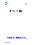
IRMS
Intelligent Redundant Multi Switch
- User’s manual - Manuale d’uso -
- ENGLISH -
Intelligent Redundant Multi Switch – User’s Manual
__________________________________________________________________________________________________________________________________
User’s manual
1
2
INTRODUCTION.....................................................................................................................................................................4
GENERAL DESCRIPTION OF THE SYSTEM ......................................................................................................................4
2.1 Load distribution.....................................................................................................................................................................4
2.2 Interventions ...........................................................................................................................................................................4
3
INSTALLATION......................................................................................................................................................................6
4
SAFETY GUIDELINES ...........................................................................................................................................................7
5
SIGNALS AND ALARMS.......................................................................................................................................................7
6
INTERFACING ........................................................................................................................................................................8
6.1 SNMP network adapter version ..............................................................................................................................................8
6.2 Serial port RS232 version .......................................................................................................................................................9
7
STRUCTURE OF THE IRMS ................................................................................................................................................10
8
USAGE AND OPERATING CONDITIONS .........................................................................................................................11
9
PACKAGING AND STORAGE ............................................................................................................................................12
10 WARRANTY..........................................................................................................................................................................12
11 TECHNICAL DATA ..............................................................................................................................................................12
3
Intelligent Redundant Multi Switch – User’s Manual
- ENGLISH -
__________________________________________________________________________________________________________________________________
1
INTRODUCTION
Congratulations for having chosen Intelligent Redundant Multi Switch (IRMS) system.
This system has been designed to allow you to install and manage eight (8) network users from a single point, using one or
two power lines, either directly from the mains power supply or via an UPS.
This User Manual contains all the information you will need regarding the installation, use, safety and maintenance of your
IRMS. Please read the following instructions carefully, as this will allow you to use the product system you have purchased to its
full potential.
Please keep this user manual in a safe place.
© All reproduction of this user manual, whether wholly or in part, is strictly prohibited, without the prior consent of
Producer reserves the right to modify the product without prior notice.
2
GENERAL DESCRIPTION OF THE SYSTEM
The IRMS (Intelligent Redundant Multi Switch) unit has been designed to allow you to install and manage eight network
users from a single point, using one or two power supply lines, either direct from the mains power supply or served by an UPS.
2.1
LOAD DISTRIBUTION
The power supplies have been designed to guarantee operation of the system under extreme conditions:
x a single line supplying 180Vac;
x two lines simultaneously providing 265Vac.
In this way, the control system is guaranteed to function even with a reduction or strong disturbance in the power supply.
2.2
INTERVENTIONS
The IRMS automatically switches the power supply to an alternative source when the loads connected to a line undergo a
blackout. The duration of the voltage blackout required to switch the power supplies can be programmed using the system’s
software.
In order to minimise the intervention time, switching does not just occur when the line voltage reaches zero, but is
instead immediate.
The system will disconnect a load when the current (RMS value) exceeds the maximum value for a single output (4A).
The disconnection of a load occurs within 0.8y1sec, on average, from the time the current value is exceeded.
The system is controlled by a microprocessor (PP), which carries out all the basic, real-time and communication
functions.
The external communication protocol ensures that all basic functions are activated and that all quantities are monitored.
The switching system is driven by a series of relays that have been designed and programmed in such a way as to
minimise the intervention times.
In order to ensure that the loads are not accidentally disconnected if a malfunction occurs to the microprocessor, a
“watch-dog” circuit automatically sets the IRMS to its default settings, i.e. with all eight users powered by the main power
supply line “A”.
Figure 1 is a block diagram of the IRMS.
4
- ENGLISH -
Intelligent Redundant Multi Switch – User’s Manual
__________________________________________________________________________________________________________________________________
Serial IN
Serial OUT
Figure 1: Block diagram of the IRMS
So that it will operate when at least one of the two lines “A” or “B” is present, the power supply is redundant.
Relays RL1, RL2, RL3, RL4, RL5, RL6, RL7, RL8 switch the output loads from line A to line B, whilst relays RL9, RL10,
RL11, RL12, RL13, RL14, RL15, RL16 disconnect the loads.
5
Intelligent Redundant Multi Switch – User’s Manual
- ENGLISH -
__________________________________________________________________________________________________________________________________
3
INSTALLATION
Remove the machine from its packaging with caution.
Attach the handles to the side of the IRMS with the appropriate screws as depicted in the Figure 2.
Figure 2: Assemblage of the handles
For greater safety and to avoid making the wrong connections, only use the cables that were supplied with the machine.
Figure 3 below shows the various possible power supply configurations of the IRMS.
Configuration (a) is the best in terms of:
x reliability;
x protection and continuity of the electrical power supply.
In configuration (c), lines “A” and “B” are either two separate lines, or are separated by two different disconnecting switches
above the IRMS system.
Figure 3: The different possible configurations of the IRMS
The IRMS measures the shift between the two power supply lines “A” and “B” and, whenever this shift exceeds 11 degrees,
displays an alarm message on the LCD display. It is important when installing the machine to ensure that the two lines “A” and
“B” are not in push-pull. Should this occur, the LCD display will indicate this, and the person installing the system should rectify
the problem by reversing the connections in the power supply.
6
- ENGLISH -
Intelligent Redundant Multi Switch – User’s Manual
__________________________________________________________________________________________________________________________________
4
SAFETY GUIDELINES
In order to ensure safe use of the equipment, a number of basic safety precautions need to be observed.
These may be summarised as follows:
x do not use the machine with wet hands;
x do not use the machine in bare feet;
x ensure that water or other liquids do not penetrate the machine;
x do not use the machine if the power supply cable is damaged;
x the IRMS must not be operated without a ground connection;
x do not pull the power supply cable to disconnect the power supply;
x do not attempt to open the machine or to repair it;
x all maintenance operations must be carried out by qualified personnel;
x ensure that children, persons unauthorised etc. do not use the machine.
5
SIGNALS AND ALARMS
The LCD display provides the user/operator with all the information relating to the operating status of the machine and warns
of any conditions that warrant an alarm.
The display has two lines: a status line (top) and a status/alarm line (bottom).
The four possible operating conditions are shown in Figure 4.
Where there is no blackout but a shift of between 0° and 11° occurs, the two lines of the LCD display show the status of the
outputs, the line data (two at a time with the delivered power in VA), and the data of the loads (1, 2, 3, etc…) connected to the
line, as shown in Figure 4-a and 4-b.
When a blackout occurs on one of the two input lines, or where a shift of more than 11° occurs between the two lines, the
LCD display indicates this on the status/alarm line (Figure 4-c and Figure 4-d).
The shift reading is given in multiples of 11.
Figure 4: LCD display
The IRMS does not emit any acoustic alarm. Presence of an alarm is indicated solely on the LCD display.
7
Intelligent Redundant Multi Switch – User’s Manual
- ENGLISH -
__________________________________________________________________________________________________________________________________
6
INTERFACING
6.1
SNMP NETWORK ADAPTER VERSION
The Network card allows you to connect the IRMS directly to an Ethernet node; the machine is controlled directly using
the SNMP protocol.
The IRMS sends information concerning the status of the system via the network (SNMP TRAP).
To configure Network card parameters refer to “Network Card User’s Manual”
3
1
2
LAN interface description (front view)
1.
2.
3.
RJ-45 socket for connection to a LAN (Ethernet);
Network card unit RS232 serial socket to configure network parameters (IP address, SNMP communities, etc.);
The RESET button allows you to reset the Network Card module
The two LEDs display provides the user/operator with the signals regarding the status of the network communications.
GREEN LED: link present on the network board
YELLOW LED: data transfer
8
- ENGLISH -
Intelligent Redundant Multi Switch – User’s Manual
__________________________________________________________________________________________________________________________________
6.2
SERIAL PORT RS232 VERSION
The serial port allows you to connect the IRMS directly to a PC; the machine is controlled using a proprietary protocol.
RS232 SERIAL
(1)
PORT
As shown in Figure 5, the machine has two RJ-12 sockets located on the rear to allow two more further IRMSs to be
connected in cascade.
CONNECT TO THE PC
SERIAL SERIAL
IN
OUT
SERIAL SERIAL
IN
OUT
SERIAL SERIAL
OUT
IN
Figure 5: RJ-12 connections
(1)
You are advised to use a cable of maximum length 3 metres.
9
Intelligent Redundant Multi Switch – User’s Manual
- ENGLISH -
__________________________________________________________________________________________________________________________________
7
STRUCTURE OF THE IRMS
Figure 6 shows the front and rear views of the IRMS, whilst Figures 7 and 8 show the input socket with circuit breaker and
the internal structure and wiring diagram of the IRMS respectively.
The IRMS has two male IEC power supply input sockets on the rear and eight female IEC output sockets on the front.
(1)
(2)
Figure 6: Front and rear view of the IRMS
(1) Front view of the SNMP Network card version
(2) Front view of the Serial port RS232 version
NOTE: The IRMS does not have an ON/OFF button. Therefore, it is necessary to disconnect the power cables and the load
cables before accessing the internal components of this machine.
NOTE: The two IEC input line sockets carry a 16A circuit breaker (Figure 7). To reset the protection, press the
correspondent button.
Figure 7: IEC input socket with circuit breaker
10
- ENGLISH -
Intelligent Redundant Multi Switch – User’s Manual
__________________________________________________________________________________________________________________________________
Figure 8: IRMS internal wiring
8
USAGE AND OPERATING CONDITIONS
Use
The IRMS has been designed to use a 180/265 Vac single-phase 50/60Hz power supply.
In line with current regulations, only use the cables that have been supplied with the machine. The power supply socket
must be easily accessible to the operator.
The purchaser of the machine undertakes to use the IRMS in suitable operating conditions, and to use it in the manner for
which it was designed, taking into account the use, importance, and the functions (whether secondary or indirect) of the
equipment that is being monitored. The Manufacturer is not responsible for indirect damage.
WARNING: The IRMS must be connected to earth when in use.
ATTENTION! A soft damp cloth may be used to clean the outside of the machine (always with the system disconnected
from the mains power supply and users).
Do not use any type of solvent as this may damage the external finishing of the machine.
ATTENTION! The IRMS has been designed exclusively for professional use.
NOTE: These instructions may be modified by the wiring regulations in force in the country where the IRMS is purchased.
Operation
The IRMS has been designed exclusively to operate indoors. It is advisable to install it in areas where no inflammable
liquids or gases, or other harmful or noxious substances, have been stored.
11
Intelligent Redundant Multi Switch – User’s Manual
- ENGLISH -
__________________________________________________________________________________________________________________________________
9
PACKAGING AND STORAGE
Packaging
The packaging is designed to protect the equipment during normal transport conditions.
It is strongly advisable to conserve the packaging in a safe place in case the equipment needs to be taken to a service
centre for maintenance or repair in the future.
It is important to check that the IRMS has not been damaged during transportation.
If the machine has been damaged in transportation return it immediately (no later than eight days from the date of
receipt).
ATTENTION!: The packaging materials may be a source of danger if left within the reach of children, etc…
Storage
Store the IRMS in a cool dry place in a horizontal position away from atmospheric agents.
Avoid knocking or bumping the casing as this might cause damage to the mechanical and electrical components of the
machine. Do not place other items on top of the IRMS if the total combined weight is five (5) times greater than the machine
itself.
Other items supplied
Along with the IRMS, the following items are also supplied:
x Two fasteners for fastening the IRMS to the rack;
x Two SCHUKO-IEC (16A) cables for the two input sockets;
x Four IEC-IEC (10A) cables for the output sockets;
x A serial communication cable cross over DB9 F/F (only for Network version);
x A serial communication cable pin-to-pin DB9 F/M (only for Serial version);
x A serial communication cable pin-to-pin DB9 RJ-12/RJ-12 (only for Serial version);
x The “Network card User’s manual” (only for Network version)
x This user manual;
10 WARRANTY
The system you have purchased has been designed and constructed in accordance with the standards laid out in CEI/EN
50091-1-1, EN 50091-2 A LEV, and CEI 74-2, EN 60950.UNI.
The IRMS is covered by a guarantee valid from the date it was bought. The guarantee does not include equipment that is
used incorrectly, or is modified due to circumstances external to the machine or to force major, is repaired by third parties, or if
the serial number has been removed or modified.
11 TECHNICAL DATA
Input voltage (V)
Maximum load each output (A)
Maximum load each input (A)
Output voltage (V)
Mean relay intervention time (ms)
Operating conditions
Storage conditions
Audible noise at 1m (3ft)
Communication ports
Casing index of protection
Safeguards
Input sockets
Circuit breaker
Output sockets
Weight (Kg)
Rack measurements
Depth
Standard compliance
(1)
12
U=44.4mm
Min. 180Vac (RMS) single-phase with one line supplying, 50/60Hz
Max. 265Vac (RMS) single-phase with two lines supplying, 50/60Hz
4
16
that of the line input voltage chosen
8
Elevation max. 3,000 m (10,000ft) / <90% non-condensing humidity / 0y40°C
Elevation max. 15,000m (50,000ft) / 0y45°C
<25dBA
1 RJ-45 10BASE-T for SNMP network adapter version
1 DB9-F RS232 for serial port RS232 version
IP20
Overload
2 IEC (16A)
16A for each input socket
8 IEC 320 (10A)
5
2U–19’’ (1)
360mm
CEI/EN 50091-1-1/EN 50091-2 A LEV/CEI 74-2/EN 60950
- ITALIANO -
Intelligent Redundant Multi Switch – Manuale d’Uso
__________________________________________________________________________________________________________________________________
Manuale d’uso
1
2
INTRODUZIONE ...................................................................................................................................................................14
DESCRIZIONE GENERALE DEL SISTEMA ......................................................................................................................14
2.1 Distribuzione dei carichi .......................................................................................................................................................14
2.2 Interventi...............................................................................................................................................................................14
3
ISTRUZIONI PER L’INSTALLAZIONE ..............................................................................................................................16
4
PRECAUZIONI PER LA SICUREZZA.................................................................................................................................17
5
SEGNALAZIONI ED ALLARMI ..........................................................................................................................................17
6
DESCRIZIONE INTERFACCIAMENTO .............................................................................................................................18
6.1 Versione con adattatore di rete SNMP..................................................................................................................................18
6.2 Versione con porta seriale RS232 .........................................................................................................................................19
7
STRUTTURA DELL’IRMS ...................................................................................................................................................20
8
CONDIZIONI DI IMPIEGO E FUNZIONAMENTO............................................................................................................21
9
IMBALLAGGIO E IMMAGAZZINAMENTO .....................................................................................................................22
10 GARANZIA ............................................................................................................................................................................22
11 DATI TECNICI.......................................................................................................................................................................22
13
Intelligent Redundant Multi Switch – Manuale d’Uso
- ITALIANO -
__________________________________________________________________________________________________________________________________
1
INTRODUZIONE
Congratulazioni per aver scelto il sistema Intelligent Redundant Multi Switch (IRMS).
Tale sistema è stato progettato per consentire la distribuzione e la gestione da remoto di otto (8) utenze di rete in un sistema
con una o due linee di alimentazione dirette o asservite da UPS.
Il presente Manuale Utente racchiude tutte le indicazioni relative l’installazione, l’impiego, la sicurezza, la manutenzione del
Vostro IRMS: un’attenta lettura delle istruzioni qui descritte permette di sfruttare al meglio le potenzialità del prodotto da Voi
acquistato.
Conservare con cura il presente manuale.
© È vietata ogni riproduzione del presente manuale, anche parzialmente, salvo autorizzazione del Produttore che si
riserva la facoltà di apportare modifiche al prodotto senza preavviso.
2
DESCRIZIONE GENERALE DEL SISTEMA
L’unità IRMS (Intelligent Redundant Multi Switch), è stata progettata per consentire la distribuzione e la gestione da remoto
di otto utenze di rete in un sistema con una o due linee di alimentazione dirette o asservite da UPS.
2.1
DISTRIBUZIONE DEI CARICHI
Gli alimentatori sono dimensionati in modo da garantire il funzionamento del sistema nelle condizioni estreme:
x una sola linea erogante 180Vac;
x due linee eroganti contemporaneamente 265Vac.
In tal modo si garantisce il funzionamento del sistema di controllo anche con alimentazione parzializzata o fortemente
disturbata.
2.2
INTERVENTI
L’IRMS gestisce la commutazione automatica sull’alimentazione alternativa per i carichi connessi ad una linea che subisce
un “blackout”. La durata del “blackout” di tensione che provoca la commutazione è programmabile via software.
Per minimizzare i tempi di intervento, la commutazione conseguente all’evento di “blackout” non viene effettuata in
concomitanza al passaggio per lo zero della tensione ma è immediata.
Quando la corrente (valore RMS) di una singola uscita supera la soglia massima consentita (4A), il sistema scollega
automaticamente il carico relativo all’uscita stessa.
La disconnessione di un carico avviene mediamente entro 0.8 y 1 sec dal momento in cui si rileva il superamento della soglia
di corrente.
Il sistema è gestito da un microprocessore (PP) che realizza tutte le funzioni di base, real-time e di comunicazione.
Il protocollo di comunicazione con l’esterno prevede l’attivazione di tutte le funzioni di base ed il monitoraggio delle
grandezze misurate.
Il sistema di commutazione è affidato ad una batteria di relè opportunamente dimensionati e comandati in modo da
minimizzarne i tempi di intervento.
Per evitare la disconnessione accidentale dei carichi, un circuito di “watch-dog” hardware nel caso di un malfunzionamento
del microprocessore pone l’IRMS nella condizione di default, ossia nella connessione di tutte le otto utenze alla linea di
alimentazione principale “A”.
La Figura 1 illustra lo schema a blocchi dell’IRMS.
14
- ITALIANO -
Intelligent Redundant Multi Switch – Manuale d’Uso
__________________________________________________________________________________________________________________________________
Solo per versione RS232
PC o
scheda di rete
Serial IN
Serial OUT
Figura 1: Schema a blocchi dell’IRMS
L’alimentatore è ridondato in modo da funzionare quando è presente almeno una delle due linee “A” o “B”.
I relè RL1, RL2, RL3, RL4, RL5, RL6, RL7, RL8 garantiscono la commutazione dalla linea A alla linea B del carico di ogni
uscita mentre i relè RL9, RL10, RL11, RL12, RL13, RL14, RL15, RL16 garantiscono la disconnessione dei carichi.
15
Intelligent Redundant Multi Switch – Manuale d’Uso
- ITALIANO -
__________________________________________________________________________________________________________________________________
3
ISTRUZIONI PER L’INSTALLAZIONE
Estrarre con cautela la macchina dal proprio imballaggio.
Fissare le maniglie ai lati dell’apparecchiatura con le viti in dotazione come illustrato in Figura 2:
Figura 2: Montaggio delle maniglie
Per maggior sicurezza e per evitare di effettuare connessioni sbagliate, utilizzare i cavi di alimentazione forniti con la macchina.
Le configurazioni possibili delle alimentazioni dell’IRMS sono illustrate in Figura 3.
La configurazione (a) è la migliore in termini di:
x affidabilità;
x protezione e continuità dell’alimentazione elettrica.
Nella configurazione (c), le due linee “A” e “B” o sono due linee differenti, o presentano a monte due sezionatori differenti.
Figura 3: Possibili configurazioni delle alimentazioni dell’IRMS
L’IRMS misura lo sfasamento tra le due linee di alimentazione “A” e “B” e, nel caso in cui lo sfasamento superi gli 11 gradi,
viene visualizzato un messaggio di allarme sul display LCD. E’ pertanto necessario verificare che all’atto dell’installazione le due
linee “A” e “B” non risultino in controfase, in questo caso il display LCD ne darà indicazione e sarà cura dell’installatore invertire
la posizione della spina del cavo di alimentazione.
16
- ITALIANO -
Intelligent Redundant Multi Switch – Manuale d’Uso
__________________________________________________________________________________________________________________________________
4
PRECAUZIONI PER LA SICUREZZA
Il rispetto di alcune norme elementari permette un utilizzo della macchina in condizioni sicure.
Tali norme possono essere così riassunte:
x non utilizzare la macchina con mani bagnate;
x non utilizzare la macchina a piedi nudi;
x evitare che acqua o altri liquidi entrino all’interno della macchina;
x non usare la macchina con cavo di alimentazione danneggiato;
x l’IRMS non deve funzionare senza collegamento di terra;
x non tirare il cavo di alimentazione per staccare la spina d’ingresso dalla presa;
x non cercare di aprire la macchina per effettuare riparazioni;
x tutte le operazioni di manutenzione devono essere eseguite da personale autorizzato;
x evitare l’utilizzo della macchina da parte di bambini, persone incapaci, ecc…;
5
SEGNALAZIONI ED ALLARMI
Il display LCD consente di fornire all’utente/operatore tutte le segnalazioni riguardanti lo stato di funzionamento della
macchina ed eventuali condizioni di allarme.
Il display presenta due righe: una riga di stato (riga superiore) ed una riga di stato/allarmi (riga inferiore).
Le possibili quattro condizioni di funzionamento sono illustrate in Figura 4.
In caso di assenza di blackout e in presenza di uno sfasamento (shift) compreso tra 0° e 11°, sulle due righe dell’LCD viene
indicato ciclicamente lo stato delle uscite, indicazione della linea (due alla volta) con la potenza erogata in VA, e indicazione del
carico (1, 2, 3, ecc…) connesso alla linea, come mostrato in Figura 4-a e 4-b.
In caso di blackout di una delle due linee di ingresso o nel caso di sfasamento tra le due linee superiore ad 11°, il display
LCD ne da indicazione sulla riga di stato/allarmi (Figura 4-c e Figura 4-d).
L’indicazione dello sfasamento è un multiplo di 11.
Figura 4: Display LCD
Per quanto riguarda gli allarmi, l’IRMS non fornisce alcun tipo di segnalazione acustica ma solo informazioni tramite il
display LCD.
17
Intelligent Redundant Multi Switch – Manuale d’Uso
- ITALIANO -
__________________________________________________________________________________________________________________________________
6 DESCRIZIONE INTERFACCIAMENTO
VERSIONE CON ADATTATORE DI RETE SNMP
6.1
La scheda di rete consente di connettere l’IRMS direttamente ad un nodo ethernet; la macchina è controllata tramite il
protocollo SNMP.
L’IRMS invia informazioni riguardanti lo stato del sistema via rete (TRAP SNMP).
Per la configurazione dei parametri della scheda di rete, riferirsi al “Network Card User’s Manual”
3
1
2
Desrizione dell’interfaccia LAN (vista frontale)
1.
2.
3.
connettore RJ-45 per la connessione alla rete LAN (Ethernet);
Connettore seriale RS232 per la configurazione dei parametri della scheda di rete (IP address, SNMP communities,
etc.);
Il pulsante RESET consente di resettare la scheda di rete
I due LED forniscono all’utente/operatore le segnalazioni sullo stato della comunicazione di rete.
LED VERDE: connessione presente sulla scheda di rete
LED GIALLO: flusso dati
18
- ITALIANO -
Intelligent Redundant Multi Switch – Manuale d’Uso
__________________________________________________________________________________________________________________________________
6.2
VERSIONE CON PORTA SERIALE RS232
La porta seriale consente di connettere l’IRMS direttamente ad un PC; la macchina è controllata tramite un protocollo
proprietario
PORTA SERIALE
(1)
RS232
Come mostrato in Figura 5, la macchina ha due prese RJ-12 collocate sul retro per consentire la connessione di due o più
IRMS in cascata.
CONNETTERE AL PC
SERIAL SERIAL
IN
OUT
SERIAL SERIAL
IN
OUT
SERIAL SERIAL
OUT
IN
Figura 5: connessioni tramite RJ-12
(1)
Si raccomanda di utilizzare un cavo di lunghezza massima 3 metri.
19
Intelligent Redundant Multi Switch – Manuale d’Uso
- ITALIANO -
__________________________________________________________________________________________________________________________________
7
STRUTTURA DELL’IRMS
La Figura 6 rappresenta la vista frontale ed il retro dell’IRMS, mentre nelle successive Figura 7 e Figura 8 vengono
rappresentate, rispettivamente la presa d’ingresso con l’interruttore termico e la struttura interna con lo schema di cablaggio.
L’IRMS è fornito di due prese di ingresso di tipo IEC maschio per l’alimentazione poste sul retro e otto prese di uscita di tipo
IEC femmina, poste sul frontale.
(1)
(2)
Figura 6: Fronte e retro dell’IRMS
(1)
(2)
Vista frontale della versione con scheda di rete
Vista frontale della versione con porta seriale RS232
NOTA: L’IRMS non ha un pulsante di ON/OFF, per cui prima di accedere alle parti interne della macchina occore disconnettere
i cavi di alimentazione dell’unità ed i cavi dei carichi ad essa collegati.
NOTA: Le spine IEC delle due linee di ingresso sono dotate di interruttore termico da 16A (Figura 7). Per ripristinare la
protezione, premere il pulsante corrispondente.
Figura 7: Spina IEC di ingresso con interruttore termico di protezione
20
- ITALIANO -
Intelligent Redundant Multi Switch – Manuale d’Uso
__________________________________________________________________________________________________________________________________
Figura 8: Cablaggio interno dell’IRMS
8
CONDIZIONI DI IMPIEGO E FUNZIONAMENTO
Impiego
L’IRMS è stato progettato per essere alimentato con tensione di 180/265Vac monofase e frequenza di 50/60Hz.
Utilizzare solo i cavi forniti con la macchina nel rispetto delle normative vigenti. La presa di alimentazione deve essere
accessibile all’operatore.
L’acquirente si impegna ad utilizzare l’IRMS in condizioni operative compatibili con la macchina stessa ed a farne un uso
ragionevole ed idoneo tenuto conto dell’utilizzo, dell’importanza e delle funzioni anche secondarie o indirette dell’apparato da
monitorare, non rispondendo il Produttore per danni indiretti.
AVVERTENZA: Durante il funzionamento l’IRMS va collegato al conduttore di terra.
ATTENZIONE! Per operazioni di pulizia esterne (da effettuarsi sempre con sistema scollegato dalla rete di alimentazione e
dalle utenze) si può utilizzare un panno morbido e umido.
Non utilizzare alcun tipo di solvente in quanto potrebbe danneggiare le finiture esterne della macchina.
ATTENZIONE! L’IRMS è stato progettato solo per un impiego professionale.
NOTA: Queste istruzioni possono essere modificate dalle norme di cablaggio in vigore localmente per ogni Nazione.
Funzionamento
L’IRMS è stato progettato per funzionare soltanto in ambienti chiusi. È bene installarlo in ambienti privi di liquidi
infiammabili, gas o altre sostanze nocive.
21
Intelligent Redundant Multi Switch – Manuale d’Uso
- ITALIANO -
__________________________________________________________________________________________________________________________________
9
IMBALLAGGIO E IMMAGAZZINAMENTO
Imballaggio
L’imballo è stato studiato per un trasporto sicuro in condizioni normali di viaggio.
È consigliabile conservare l’imballo in luogo sicuro, nel caso in cui, in futuro, l’unità dovesse essere consegnata ad un centro
assistenza per manutenzione o riparazione.
È importante ispezionare visivamente l’IRMS per assicurarsi che non si siano verificati danni durante il trasporto.
In caso vengano rilevati danni alla struttura, restituire la macchina tempestivamente e non oltre gli otto giorni dalla data di
ricevimento.
ATTENZIONE!: Gli elementi dell’imballaggio possono essere fonte di pericolo se lasciati alla portata di bambini, incapaci, ecc…
Immagazzinamento
Conservare l’IRMS in posizione orizzontale e in un luogo fresco e asciutto, nonché al riparo dagli agenti atmosferici.
Evitare urti contro l’imballaggio: potrebbero causare danni sia alla parte meccanica che a quella elettronica della macchina.
Non sovrapporre sull’imballaggio altre macchine o contenitori per un peso superiore a cinque (5) volte il peso della macchina
stessa.
Dotazione di serie
La dotazione di serie prevede i seguenti accessori:
x Due maniglie di fissaggio al rack;
x Due cavi SCHUKO-IEC (16A) per le due prese di ingresso;
x Quattro cavi IEC-IEC (10A) per le prese di uscita;
x Un cavo di collegamento seriale cross over DB9 F/F (solo per versione con scheda di rete);
x Un cavo di collegamento seriale pin-to-pin DB9 F/M (solo per versione con porta seriale);
x Un cavo di collegamento seriale pin-to-pin RJ-12/RJ-12 (solo per versione con porta seriale);
x Il manuale “Network card user’s manual” (solo per versione con scheda di rete)
x Il presente manuale;
10 GARANZIA
Il sistema da Voi acquistato è stato progettato e costruito secondo gli standard di progettazione e costruzione CEI/EN 500911-1, EN 50091-2 A LEV, CEI 74-2, EN 60950.UNI.
L’IRMS è coperto da una garanzia dalla data di acquisto: la garanzia non si riferisce a prodotti che siano stati utilizzati in
modo sbagliato, modificati per cause di forza maggiore o esterne al prodotto, riparate da terzi, o se il numero di serie è stato
rimosso o modificato.
11 DATI TECNICI
Tensione di ingresso (V)
Carico massimo per ogni uscita (A)
Carico massimo per ogni ingresso (A)
Tensione di uscita (V)
Tempo medio intervento dei relè (ms)
Condizioni di utilizzo
Condizioni immagazzinamento
Rumorosità a 1m
Porte di comunicazione
Grado di protezione dell’involucro
Protezioni
Prese di ingresso
Interruttore termico
Prese di uscita
Peso (Kg)
Dimensioni del rack
Profondità
Norme osservate
(1)
22
U=44.4mm
Min. 180Vac (RMS) monofase con una linea erogante, 50 / 60 Hz
Max. 265Vac (RMS) monofase con due linee eroganti, 50 / 60 Hz
4
16
È la tensione della linea di ingresso selezionata
8
Altitudine max 3000m / <90% umidità non condensante / 0y40°C
Altitudine max 15.000m/0y45°C
<25dBA
1 RJ-45 10BASE-T per versione con adattatore di rete SNMP
1 DB9-F RS232 per versione con porta seriale RS232
IP20
Sovraccarico
2 IEC (16A)
16A per ogni presa di ingresso
8 IEC 320 (10A)
5
2U–19’’ (1)
360mm
CEI/EN 50091-1-1/EN 50091-2 A LEV/CEI 74-2/EN 60950
0MNURMSNPA