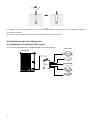
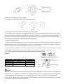
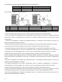
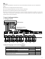
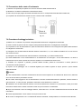
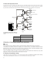
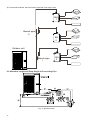
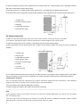
1
MANUALE UTENTE - INSTALLATORE PER UNITA’ ESTERNE SUPER DC
IT
USER’S – INSTALLER’S MANUAL FOR SUPER DC OUTDOOR UNITS
EN
UNITÀ ESTERNE / OUTDOOR UNITS
MODELLI / MODELS
N-BD8M140A3
N-BD9M160A3
Questo manuale è stato creato per scopo informativo. La ditta declina ogni responsabilità per i risultati di una progettazione o di una installazione
basata sulle spiegazioni e le specifiche tecniche riportate in questo manuale. E’ inoltre vietata la riproduzione anche parziale sotto qualsiasi forma
dei testi e delle figure contenute in questo manuale.
This manual has been created for informative purposes. The company declines any responsibility for the results of projects or installations based on
the explanations and the technical specifications provided in this manual. It is besides forbidden the reproduction under any form of the texts and of
the figures contained in this manual.
Serie / Series / Serie / Serie / Série
MANUALE UTENTE-INSTALLATORE
USER’S-INSTALLER’S MANUAL
SUPER DC INVERTER 3 PHASE
Emissione / Issue
Sostituise / Supersedes
02 - 2014
-
Catalogo / Catalogue / Catálogo / Katalog / Catalogue
MUI140348E3001-00
1
I prodotti elettrici ed elettronici di eventuale scarto non dovranno essere disposti con i
normali rifiuti domestici, ma smaltiti a norma di legge RAEE in base alle direttive Europee
2002/96/CE e suc-cessive modifiche 2003/108/CE, informandosi presso il Comune di
residenza o presso il rivenditore nel caso in cui il prodotto venga sostituito con uno analogo.
Possible electrical or electronic rejected devices/products should not be located together with
normal domestic waste, but disposed according to the current WEEE law in compliance with
the 2002/96/EC European Directive and with the 2003/108/EC following amendments.
Should you decide to replace this product with a new one, please, address your local
Administration or your reseller.
ITALIANO
CONTENTS
1 Precauzioni di sicurezza----------------------------------------------------------------------------------------------------------------------- 3
2 Precauzioni per l’installazione --------------------------------------------------------------------------------------------------------------- 4
2.1 Precauzioni per il gas refrigerante R410A---------------------------------------------------------------------------------------------- 4
2.2 Precauzione per l’installazione ------------------------------------------------------------------------------------------------------------ 4
2.3 Precauzioni per il test di funzionamento ------------------------------------------------------------------------------------------------ 4
2.4 Accessori --------------------------------------------------------------------------------------------------------------------------------------- 4
3 Introduzione di prodotto ----------------------------------------------------------------------------------------------------------------------- 4
3.1 Nomi delle parti principali dell’unità esterna-------------------------------------------------------------------------------------------- 5
3.2 Combinazioni delle unità esterne ed interne ------------------------------------------------------------------------------------------- 5
3.3 Parti dell’Unità --------------------------------------------------------------------------------------------------------------------------------- 5
3.4 Temperatura di operazione ---------------------------------------------------------------------------------------------------------------- 6
4 Selezione luogo di installazione e Precauzioni ------------------------------------------------------------------------------------------ 6
4.1 Selezione luogo di installazione----------------------------------------------------------------------------------------------------------- 6
4.2 Dimensioni ------------------------------------------------------------------------------------------------------------------------------------- 7
4.3 Spazio di installazione e di servizio ------------------------------------------------------------------------------------------------------ 7
5 Istruzioni di installazione ---------------------------------------------------------------------------------------------------------------------- 7
6 Installazione dei tubi refrigerante------------------------------------------------------------------------------------------------------------ 8
6.1 Installazione con distributori BU e giunti ------------------------------------------------------------------------------------------------ 8
6.2 Lunghezza e dislivello consentiti delle tubazioni di refrigerante------------------------------------------------------------------10
6.3 Dimensione tubo di collegamento -------------------------------------------------------------------------------------------------------10
6.4 Collegamento giunto a Y-------------------------------------------------------------------------------------------------------------------10
6.5 Collegamento tubo di refrigerante -------------------------------------------------------------------------------------------------------11
6.6 Collegamento tubazione del refrigerante ----------------------------------------------------------------------------------------------13
6.7 Prova di tenuta -------------------------------------------------------------------------------------------------------------------------------13
6.8 Realizzazione del Vuoto -------------------------------------------------------------------------------------------------------------------14
6.9 Carica refrigerante --------------------------------------------------------------------------------------------------------------------------14
7 Lavori di cablaggio elettrico------------------------------------------------------------------------------------------------------------------17
7.1 Cablaggio elettrico --------------------------------------------------------------------------------------------------------------------------17
7.2 Requisiti del gruppo e del cavo di alimentazione ------------------------------------------------------------------------------------17
7.3 Requisiti di messa a terra------------------------------------------------------------------------------------------------------------------18
7.4 Precauzioni per i lavori di cablaggio elettrico -----------------------------------------------------------------------------------------18
7.5 Precauzioni dello strato di isolamento --------------------------------------------------------------------------------------------------19
7.6 Procedure di cablaggio elettrico ---------------------------------------------------------------------------------------------------------19
8 Tubo di drenaggio------------------------------------------------------------------------------------------------------------------------------21
8.1 Installazione del tubo di drenaggio ------------------------------------------------------------------------------------------------------21
8.2 Design del tubo di drenaggio -------------------------------------------------------------------------------------------------------------20
9 Installazione del materiale d’isolamento--------------------------------------------------------------------------------------------------20
10 Prova di funzionamento---------------------------------------------------------------------------------------------------------------------21
10.1 Controlli dopo l’installazione-------------------------------------------------------------------------------------------------------------21
10.2 Prova di funzionamento ------------------------------------------------------------------------------------------------------------------21
11 Introduzione alla scheda di test -----------------------------------------------------------------------------------------------------------22
11.1 Componenti della scheda di test -------------------------------------------------------------------------------------------------------22
11.2 Istruzioni delle sezioni funzione e dati ------------------------------------------------------------------------------------------------22
12 Malfunzionamenti-----------------------------------------------------------------------------------------------------------------------------23
12.1 Errori e Cause Relativi Al Condizionatore -------------------------------------------------------------------------------------------23
12.2 Soluzioni malfunzionamenti -------------------------------------------------------------------------------------------------------------24
12.3 Descrizione degli errori -------------------------------------------------------------------------------------------------------------------24
13 Manutenzione ---------------------------------------------------------------------------------------------------------------------------------27
13.1 Batteria condensante esterna-----------------------------------------------------------------------------------------------------------27
13.2 Tubo di drenaggio -------------------------------------------------------------------------------------------------------------------------27
13.3 Controlli prima inizio stagione-----------------------------------------------------------------------------------------------------------27
13.4 Manutenzione dopo fine stagione------------------------------------------------------------------------------------------------------27
ANNESSO SCHEMI ELETTRICI ---------------------------------------------------------------------------------------------------------------2
1 Precauzioni di sicurezza
Avvertimento!: Questo simbolo indica che l'utilizzo improprio può causare gravi ferite alle persone o lesioni
Cautela!: Questo simbolo indica che l’utilizzo improprio può causare danni a persone o cose
Seguire queste istruzioni per completare il processo di installazione dell’unità.
Si prega di leggere attentamente questo manuale prima di avviare l’unità.
Prima dell'installazione, controllare se la tensione e la frequenza dell'alimentazione sono in conformità con i
dati riportati sulla targhetta dell'unità.
Assicurarsi di utilizzare accessori e parti corrette per evitare perdite di acqua, scosse elettriche e incendi.
Il cavo dell’alimentazione elettrica deve avere dimensioni appropriate. Se il cavo di alimentazione o di
collegamento è danneggiato si prega sostituirlo esclusivamente con un altro.
Effettuare la saldatura sotto azoto.
Prima di mettere l’apparecchio in funzione, collegare il filocomando, altrimenti non può essere utilizzato.
L'installazione deve essere eseguita da personale qualificato.
Non tentare di installare l'apparecchio da soli. Un uso improprio può causare perdite di acqua, scosse
elettriche od incendi ecc.
Assicurarsi che la messa a terra dell'unità venga eseguita prima di collegare l'apparecchio alla presa di
corrente elettrica. Si prega di non collegare il cavo di messa a terra alle tubazioni del gas, tubazioni acqua,
parafulmini e linee telefoniche.
In caso di perdita di refrigerante durante l'installazione, si prega di ventilare immediatamente il locale.
Se il gas refrigerante viene a contatto con il fuoco si può produrre un gas tossico.
Dopo la connessione del cavo di alimentazione, si prega di fissare correttamente il coperchio della scatola
elettrica al fine di evitare incidenti.
Non cortocircuitare o eliminare il pressostato per evitare danni all'unità.
Prima di utilizzare l'apparecchio, controllare che le tubazioni e cablaggi siano corretti per evitare perdite
d'acqua, perdite di refrigerante, scosse elettriche o incendi ecc.
Non inserire oggetti nella griglia di uscita/ingresso aria.
Non collegare/scollegare il cavo di alimentazione per accendere/spegnere l'unità.
Non permettere ai bambini di utilizzare l'unità.
Spegnere l'unità o scollegare l'alimentazione elettrica prima di pulirla, altrimenti potrebbero verificarsi scosse
elettriche o lesioni.
Non esporre l'unità ad umidità o gas corrosivi.
In modalità di raffreddamento, si prega di non impostare il condizionatore ad una temperatura troppo bassa, è
consigliato mantenere una differenza di temperatura di circa 5°C tra l'interno e l'esterno
Se viene percepito qualcosa di anomalo (come odore di bruciato), spegnere l'apparecchio e togliere
l'alimentazione principale, dopodiché contattare immediatamente il centro assistenza autorizzato. Se
l’anomalia persiste, l'unità potrebbe essere danneggiata e causare scosse elettriche o incendi.
Aprire porte e finestre per mantenere una buona ventilazione.
L'unità verrà spenta dopo aver funzionato per almeno 5 minuti per non influire sul ritorno dell'olio del
compressore.
Non utilizzare l'apparecchio con mani bagnate.
Non spruzzare acqua sull'unità, ciò potrebbe causare malfunzionamenti o scosse elettriche.
Alimentare l'unità 8 ore prima dell'avviamento. Si prega di collegare l'alimentazione 8 ore prima della messa
in funzione.
Sostanze volatili, come ad esempio diluenti o gas potrebbero danneggiare l'aspetto dell'unità. Usare solo un
panno morbido con un po' di detergente neutro per pulire l'involucro esterno dell'unità,
L’utente non è autorizzato di riparare l'unità. Riparazioni effettuate da personale non qualificato e non
autorizzato potrebbero causare scosse elettriche o incendi. Si prega perciò di contattare il centro assistenza.
3
L'azienda declina ogni responsabilità per lesioni personali o danni all'apparecchiatura causati da errata installazione e
la messa in esercizio non è necessaria e dal mancato rispetto delle procedure e le istruzioni presente nel manuale,
seguire le regole e le istruzioni riportate nel presente manuale.
2 Precauzioni per l’installazione
2.1 Precauzioni per il gas refrigerante R410A
♦ Le tubazioni del refrigerante devono essere pulite ed asciutte.
♦ Il gas R410A è un refrigerante misto, quando si aggiunge il refrigerante all'unità, si deve mantenere il refrigerante
nello stato liquido. La composizione particolare del gas refrigerante si cambia se esso è nello stato gas, e perciò la
capacità dell'unità diminuirà.
♦ Quando si presenta una perdita del refrigerante, si prega di non toccarlo con le mani. Altrimenti il refrigerante
fuoriuscito può provocare congelamento.
♦ E’ raccomandabile non lasciare che una grande quantità di refrigerante si disperda nell'ambiente, perché esso
causa l'aumento dell'effetto serra. Ciò può produrre gas tossici quando il refrigerante viene a contatto con il fuoco.
2.2 Precauzioni per l’installazione
♦ L'unità è molto pesante (più di 110kg), quindi è necessaria la presenza di più di due persone per sollevarla.
♦ Durante la rimozione dell'unità, si consiglia di utilizzare i guanti e di posizionarsi negli angoli, prestando attenzione a
non urtare le alette che risultano taglienti.
♦ Si prega di gettare i residui nel bidone della spazzatura dopo l'installazione.
2.3 Precauzioni per il test di funzionamento
Per proteggere il compressore da vibrazione durante il trasporto, vengono utilizzate 2 guarnizioni metalliche. Esse
devono essere rimosse prima della messa in servizio e fissare saldamente il dado altrimenti l'apparecchio potrebbe
non funzionare bene.
2.4 Accessori
Consultare l'elenco degli accessori del condizionatore nell'imballaggio dell'apparecchio.
3 Introduzione al prodotto
Questa serie adotta la tecnologia del compressore inverter. La variazione dello spostamento del compressore,
permette una modulazione continua della capacità nell'intervallo di 10% ~ 100%. Prodotti dotati di capacità da 14kW a
16kW possono essere ampiamente usati per applicazioni abitazioni residenziali, negozi commerciali, alberghi e
specialmente nei posti con carichi variabili.
4
3.1 Nomenclatura delle parti principali dell’unità esterna
NO
Descrizione
1
Motore ventilatore
2
Pala ventilatore assiale
3
Scatola componenti elettrici
4
Valvola di intercettazione tubo gas
5
Valvola di intercettazione tubo liquido
3.2 Combinazioni delle unità esterne ed interne
Quantità di unità interne da collegare
Capacità totale delle unità interne da collegare (Btu/h)
N-BD8M140A3
N-BD9M160A3
2
8
2400
64000
2
9
2800
72000
3.3 Parti dell’Unità
Per questa serie, un’unità esterna è in grado di pilotare fino a 3 distributori BU e 9 unità interne comprendendo le
tipologie quali cassette, canalizzati, parete, pavimento-soffitto e console. L'unità esterna rimane accesa fino a quando
una qualsiasi unità interna riceve il comando di operazione e si spegne una volta che tutte le unità interne si fermano.
5
Unità interna
C a ss e tta
BU
1
Canalizzato
Alimentazione
(5 0 H z ,2 2 0 V )
Messa a terra
A parete
Giunto a Y
2
BU
2
Alimentazione
(5 0 H z ,2 2 0 V )
G ro u n d
Unità esterna
Giunto a Y
1
BU
3
Messa a terra
Messa a terra
Alimentazione (5 0 H z ,3 8 0 V )
Alimentazione
(5 0 H z ,2 2 0 V )
Fig. 2
3.4 Temperature di funzionamento
Tabella 2
Tipo
Temperatura esterna DB(°C)
Massimo raffreddamento
48
Minimo raffreddamento
10
Massimo riscaldamento
27
Minimo riscaldamento
-15
4 Selezione luogo di installazione e Precauzioni
Cautele!
♦ L'installazione del condizionatore d’aria deve essere conforme alle leggi e ai regolamenti nazionali e locali.
♦ La tipologia di installazione influirà direttamente sulla capacità del condizionatore d'aria. L'installazione di questo
apparecchio deve essere fatta da un centro assistenza tecnico autorizzato. Si prega di contattare il rivenditore
dell’apparecchio al momento dell’acquisto. Un installatore qualificato è in grado di realizzare l'installazione ed il
collaudo secondo le istruzioni contenute nel manuale d’installazione.
♦ Non installare l'unità vicino a una zona dove ci sono piccoli animali, fumo o incendi potrebbero causare
malfunzionamenti. Si prega di tenere la zona intorno all'unità pulita.
4.1 Selezione luogo di installazione
♦ L’unità deve essere installata in un luogo non umido e con una buona ventilazione.
♦ Accertarsi che il rumore e l’aria di scarico dell'unità esterna non diano disturbi ai vicini.
6
♦ Installare l'unità esterna in un luogo ben ventilato e più vicina se possibile all’unità interna.
♦ Installare l'unità esterna in un luogo fresco e non deve essere esposta direttamente ai raggi solari o radiazioni di
fonte di calore ad elevata temperatura.
♦ Non installare l'unità esterna in un luogo sporco o molto inquinato, in modo da evitare l’intasamento del proprio
scambiatore di calore.
♦ Non installare l'unità esterna dove vi è petrolio, aria salata o in un luogo contenente dei gas nocivi quali: gas
solforosi.
Cautela!
Non installare l'unità nei seguenti luoghi per evitare malfunzionamenti. Se è inevitabile, si prega di contattare il centro
di assistenza autorizzato.
♦ Dove vi è petrolato.
♦ Dove l'aria è salmastra (vicino alle coste).
♦ Dove vi sono gas caustici (p.e. sulfidi) nell'aria (p.e. vicino a fonti di calore).
♦ Dove vi sono forti sbalzi di tensione.
♦ Nelle cucine dove si utilizza il gas.
♦ Dove vi sono forti onde elettromagnetiche.
♦ Dove vi sono materiali o gas infiammabili.
♦ Dove vi è evaporazione di liquidi acidi o alcalini.
♦ Dove vi sono altre situazioni particolari.
4.2 Dimensioni
900
340
1350
572
140
378
Fig. 3 (unit: mm)
7
4.3 Spazi di installazione e di servizio
1) Quando un’unità esterna deve essere installata in un posto sempre esposto a un forte vento come su una costa o
sul tetto di un palazzo molto alto, assicurare che il funzionamento della ventola sia normale usando un condotto o una
protezione antivento.
2) In caso di installazione di una singola unità esterna.
In caso di presenza di ostacoli intorno all'unità esterna, lo spazio di installazione richiesto è illustrato in Fig. 4.
3) In caso di installazione di molte unità esterne (2 o più unità)
In caso di installazione di molte unità, lo spazio di installazione richiesto è illustrato Fig. 5.
Fig. 4 (unità: mm)
Fig. 5 (unità: mm)
5 Istruzioni di installazione
1) Controllare il luogo di installazione e assicurarsi che l'area sia stabile ed in piano, in modo che l'unità non produca
vibrazioni o rumore quando viene avviata dopo l'installazione.
2) Si prega di realizzare 4 fori nella posizione di installazione, rispettando la figura della fondazione seguente.
A: Lato uscita aria
B: Vista dal basso (unità: mm) C: Foro di drenaggio
3) Fissare saldamente l'unità con i bulloni di fondazione. È possibile acquistare localmente i bulloni di fissaggio M8,
M10, dadi e rondelle.
8
Fig. 7
4) Utilizzare gomma o ammortizzatori a molla durante l'installazione dell'unità esterna per soddisfare i requisiti di
rumorosità e vibrazioni.
5) Avvitare i bulloni di fondazione nel luogo di installazione come indicato in figura 7.
6 Installazione dei tubi refrigerante
6.1 Installazione con distributori BU e giunti
1) In caso di 1 distributore BU, è possibile collegare fino a 5 unità interne.
Unità interna
Unità esterna
BU
9
2) In caso di 2 distributori BU, è possibile collegare fino a 9 unità interne.
Unità interna
BU
1
Unità esterna
Giunto a Y
BU
2
3) In caso di 3 distributori BU, è possibile collegare fino a 9 unità interne.
BU
1
G iunto a Y
2
BU
2
U nità esterna
G iun to a Y
1
BU
3
10
6.2 Lunghezza e dislivello consentiti delle tubazioni di refrigerante
Unità esterna
Secondo
giunto a Y
Primo giunto a Y
Unità interna
Fig. 11 (9 unità interne)
1A;1B;1C;2A;2B;2C;3A;3B
L4+1B; L2+L5+2A; L2+L3+3B
H1
H2
Lunghezza
consentita (m)
≤55
≤80
≤90
≤15
≤40
≤30
≤30
H3
≤15
H4
L1
≤15
≥5
Lunghezza
minima possibile
Tubi
Massima
lunghezza
consentita
Massima
altezza
consentita
Minima
lunghezza
consentita
Tra unità esterna e distributore BU
N-BD8M140A3
Tra unità interna e
distributore BU
N-BD9M160A3
Tra unità interna e distributore BU
Tra unità interna e primo giunto
Tra unità interna ed esterna
Tra unità esterne e distributore BU
Tra il distributore BU3 e gli altri distributori
BU1 e BU2
Tra un unità interna e le altre unità interne
Tra unità esterna e primo giunto
L1+L2+L3+L4+L5
1A+1B+1C+2A+2B+2C+3A+3B+3C
Tra distributore BU e giunto
L3; L4; L5
6.3 Dimensione tubo di collegamento
Unità interna in (Btu/h)
Modelli delle unità esterne
Tra unità esterna e primo giunto a Y
Tra primo e secondo giunto a Y
11
7000/9000/12000
18000
21000/24000
N-BD8M140A3
N-BD9M160A3
Il tubo L1
Il tubo L2
Tubo gas (mm)
Φ9.52
Φ12.7
Φ15.9
Tubo liquido (mm)
Φ6.35
Φ6.35
Φ9.52
Φ15.9
Φ9.52
Φ19.05
Φ15.9
Φ9.52
Φ9.52
6.4 Collegamento giunto a Y
1) In caso di utilizzo di tre distributori BU, selezionare il giunto a Y di tipo FQ01A/A.
FQ01A/A (Tubo liquido)
FQ01A/A (Tubo gas)
Fig. 12
2) Il giunto a Y è dotato di tubi ausiliari per regolare i diametri dei tubi vari. Se la dimensione del tubo selezionato è
diversa di quelle del giunto a Y, tagliare il tubo di rame in mezzo con tagliatubi ed eliminare le sbavature. Si prega di
procedere come nella figura sottostante.
Uscita
Ingresso
Ingresso
Uscita
Tagliare in mezzo
Tagliare in mezzo
Tagliare in mezzo
Tagliare in mezzo
Tagliare in mezzo
Fig. 13
3) Il tubo a Y deve essere installato in direzione verticale o orizzontale. Si prega di mantenere il tubo diretto per una
lunghezza di almeno 500 mm sull’ingresso del giunto a Y.
Entro ±30°
Entro ±30°
Fig. 14
6.5 Collegamento del tubo refrigerante
6.5.1 Precauzione per il collegamento
1) Il collegamento dei tubi deve essere effettuato rispettando le regole sottostante:
① L'unità esterna deve essere installata il più vicino possibile all'unità interna in modo da minimizzare la lunghezza
delle tubazioni e la quantità di curve.
② Il dislivello tra l'unità esterna e le unità interne deve essere il più breve possibile.
2) L'operazione di brasatura deve essere effettuata rigorosamente in conformità con i requisiti del processo. Durante
l'installazione, non danneggiare le tubazioni.
6.5.2 Processo di svasatura
① Utilizzare la tagliatubi per tagliare il tubo di collegamento nel luogo appropriato e rimuovere la sbavatura dal tubo.
② Prima dell’operazione di svasatura inserire il dado svasato.
③ Controllare bene la parte svasata, se danneggiata oppure no.
12
Fig. 14
6.5.3 Precauzioni per operazione piegatura
① Le piegature del tubo vanno fatte a mano per non deformarlo.
SI
No
Fig. 16
② Non piegare il tubo refrigerante ad un diametro che supera i 200mm.
③ Non piegare il tubo refrigerante se l'isolamento termico non viene rimosso della parte interessata dello stesso.
Altrimenti, il tubo può rompersi. Si tratta di fare un'incisione circolare con un coltello nell'isolamento termico e di
rimuoverlo. Al termine dei lavori di piegatura del tubo, si prega di ricuperare l'isolamento termico con nastro isolante.
6.5.4 Procedura di installazione della tubazione del refrigerante
① Rimuovere i tappi dai tubi
② Allineare l'estremità svasata del tubo di rame con il centro del giunto a Y. Serrare i dadi con le mani. (Se l'estremità
svasata del tubo di rame e il centro del giunto a Y non sono in linea coassiale, si prega di non utilizzare le chiavi per
stringere i dadi perché potrebbero danneggiarsi serrandoli con troppa forza).
③ Stringere i dadi di svasatura con una chiave dinamometrica fino a sentire un "click". (La chiave inglese e la chiave
dinamometrica coppia di torsione devono essere entrambe perpendicolari alla tubazione refrigerante).
④ La coppia di torsione necessaria per serrare i dadi è indicata nella tabella seguente.
Tablella 5
Raccordo per
unità interna
Diametro tubo
Φ6.35 mm
Φ9.52 mm
Φ12.7 mm
Φ15.9 mm
Φ19.05 mm
Spessore tubo di rame
≥0.8 mm
≥0.8 mm
≥0.8 mm
≥1.0 mm
≥1.0 mm
Copia di torsione
15~30 N·m
35~40 N·m
45~50 N·m
60~65 N·m
70~75 N·m
Dado svasato
Raccordo
Chiave dinamometrica
Chiave
Fig. 17
Cautele!
♦ Durante il collegamento dell'unità interna ed il giunto a Y al tubo refrigerante, non tirare con forza i giunti dell'unità
interna e il giunto a Y, altrimenti, il tubo capillare o altri tubi potrebbero rompersi causando perdite del gas refrigerante.
♦ Il tubo refrigerante deve essere sostenuto con staffe, può darsi che l’unità non sopporta il peso delle tubazioni.
♦ Tutti i tubi del sistema devono essere etichettati al fine di identificare per quale impianto appartengono in modo da
non sbagliare sull’esattezza del loro appartenenza.
13
6.6 Collegamento tubazione del refrigerante
Tubo liquido
Dado svasato
Tubo gas
NO
①
Nome
Pannello coperchio
NO
⑤
Name
Valvola arresto liquido
NO
A
Nome
Connessione frontale
②
Pannello laterale
posteriore
⑥
Piastra connessione
a destra
B
Connessione
inferiore
③
Pannello laterale
frontale
④
Valvola arresto gas
⑦
Piastra connessione frontale
C
Connessione laterale
D
Connessione
posteriore
1) Rimuovere il pannello coperchio, pannello laterale frontale, piastra di connessione a destra e piastra di
connessione frontale.
2) Le tubazioni del refrigerante possono essere installate nelle quattro direzioni, si prega quindi di selezionare la
direzione corretta.
3) Battere con un martello e trapano i fori nella piastra di connessione della direzione selezionata.
4) Collegare i tubi alle valvole d’intercettazione.
5) Piegare i tubi per farli passare attraverso i fori eseguiti nella piastra di connessione.
6) Coprire i fori di passaggio tubi con un materiale sigillante per evitare l’ingresso di acqua, polvere o piccoli animali
nell'unità esterna.
6.7 Prova di tenuta
1) Assicurarsi che le valvole di intercettazione dell'unità esterna siano chiuse durante l'operazione.
2) La prova di tenuta deve essere eseguita con gas azoto in pressione.
3) Aprire le manopole alta e bassa pressione (Hi/Lo).
4) Aprire la valvola di riduzione di pressione, mettere lentamente i tubi di collegamento sotto pressione di 1,0 MPa (10
bar), attendere almeno 15 minuti, e assicurarsi che la pressione non si abbassi.
5) Aumentare lentamente la pressione fino a 4,0 MPa (40 bar), attendere 24 ore, e assicurarsi che la pressione non si
abbassi.
6) Se la pressione non diminuisce, i tubi hanno superato il test di tenuta. Altrimenti cercare le eventuali perdite.
14
1: Unità esterna
2: Valvola di intercettazione del liquido
3: Valvola di intercettazione del gas
4: Manometro
5: Manopola alta pressione
6: Manopola bassa pressione
7: Valvola riduzione pressione
8: Bombola di azoto
Fig. 19
6.8 Realizzazione del Vuoto
1) Assicurarsi che le valvole di intercettazione di liquidi e gas siano completamente chiuse durante l’operazione di
realizzazione del vuoto.
2) Usare la pompa a vuoto per aspirare l’aria dai tubi refrigerante installati come mostrato nella figura seguente.
3) Accendere la pompa a vuoto e aprire le manopole per evacuare il gas/aria presente nei tubi del liquido e gas.
4) Quando la pressione del sistema è inferiore a -0.1Mpa (-1bar), mantenere il sistema sotto questa pressione per più
di un'ora.
1: Unità esterna
2: Valvola di intercettazione del liquido
3: Valvola di intercettazione del gas
4: Manometro
5: Indicatore alta pressione
6: Indicatore bassa pressione
7: Pompa per vuoto
Fig. 20
5) Chiudere le manopole (Lo/Hi) dopodiché spegnere la pompa a vuoto, se la pressione del manometro rimane
invariata per 2 ore, ciò significa che il vuoto è stato realizzato. In caso contrario, qualche raccordo o tubazione
presenta fessure che potrebbero causare poi perdite di gas, si prega quindi di cercarle e ripararle.
6.9 Carica refrigerante
6.9.1 L'unità esterna è carica di refrigerante al momento della spedizione dalla fabbrica ma, può essere necessaria
una carica da aggiungere nelle tubazioni refrigerante durante l’installazione.
6.9.2 Calcolo della quantità refrigerante addizionale
1) Riferirsi alla targhetta dell’unità esterna per quanto riguarda la quantità refrigerante caricata in fabbrica.
------------------------------------------------------------------------------------------------------------------------------------------------------------Note:
♦ La carica di refrigerante dell'unità esterna non comprende la carica aggiunta nell'unità interna, distributore BU e il
tubo del refrigerante.
♦ La lunghezza delle tubazioni verrà decisa nel luogo di installazione, la carica di quantità refrigerante aggiuntiva
dipende dalla dimensione e dalla lunghezza delle tubazioni al momento dell'installazione.
♦ Non c'è bisogno di aggiungere gas quando la lunghezza totale dei tubi del liquido è inferiore a 30 m.
15
------------------------------------------------------------------------------------------------------------------------------------------------------------2) Calcolo della quantità refrigerante addizionale in [kg]
Carica refrigerante addizionale (kg) = Σ [Lunghezza tubo liquido di diametro Φ6.35]×0.022kg/m +Σ [Lunghezza tubo
liquido di diametro Φ9.52] ×0.054kg/m - 1.47(kg)
♦ Se la carica di refrigerante addizionale è negativa, non c’è bisogno di aggiungere il gas refrigerante.
3) Esempio: N-BD9M160A3
Unità interna
BU
2
Unità esterna
2A
1
2B
2
2C
1A
BU
1
1B
1C
3
4
5
6
Tabella 6
Unità interna 2
Unità interna 2
Unità interna 3
Unità interna 4
Unità interna 5
Unità interna 6
Tipo unità
Cassette
Canalizzato
A parete
A parete
Canalizzato
A parete
Capacità
3500 W
2600 W
2200 W
2600 W
2600 W
2600 W
Tabella 7
L1
L2
L4
1A
1B
1C
2A
2B
2C
Diametro(mm)
Φ9.52
Φ9.52
Φ9.52
Φ6.35
Φ6.35
Φ6.35
Φ6.35
Φ6.35
Φ6.35
Lunghezza(m)
20
10
10
5
5
5
5
5
5
La lunghezza totale delle tubazioni del liquido: 20+10+10+5+5+5+5+5+5=70(m).
Di conseguenza, la lunghezza totale è maggiore di 30 m, è necessario perciò aggiungere del gas refrigerante al
condizionatore.
♦ Carica refrigerante addizionale
Σ [Lunghezza tubo di diametro Φ6.35] × 0.022kg/m +Σ [Lunghezza tubo di diametro Φ9.52] × 0.054kg/m - 1.47(kg)
=(5+5+5+5+5+5)(m) × 0.022kg/m + (20+10+10)(m)×0.054kg/m - 1.47(kg)
=1.35(kg)
16
4) Registrazione quantità refrigerante addizionale per futura manutenzione
Diametro (mm)
Φ6.35
Φ6.35
Totale
Lunghezza totale(m)
Carica refrigerante addizionale(kg)
6.9.3 Procedura di aggiunta del gas refrigerante
NO
Nome
NO
Nome
1
Unità esterna
6
Alta pressione (AP)
2
Porta di servizio
7
Bassa pressione (BP)
3
4
5
Valvola di arresto del liquido Valvola di arresto del gas Manometro
8
9
Serbatoio refrigerante R410A
Bilancia
1) Il sistema è sotto vuoto se le valvole di arresto del liquido e del gas non sono state aperte:
① Riferirsi alla parte sinistra della Fig. 22 per collegare il sistema al serbatoio del refrigerante R410A.
② Aprire il serbatoio del refrigerante R410A e la manopola di alta pressione (Hi), caricare il refrigerante nell'unità
esterna dalla valvola di intercettazione sul lato liquido. La manopola di bassa pressione (Lo) deve essere chiusa
completamente.
③ Chiudere immediatamente il serbatoio del refrigerante R410A e la manopola di alta pressione (Hi) dopo aver
aggiunto la quantità refrigerante necessaria.
④ Ruotare lentamente in senso antiorario e aprire completamente le valvole di intercettazione del liquido e lato gas.
2) Se la pressione del sistema è troppo alta, per ricaricare il refrigerante si deve agire come segue:
① Ruotare lentamente in senso antiorario e aprire completamente le valvole di arresto del liquido e del lato gas.
② Accendere l'alimentazione per avviare il condizionatore d'aria in modalità di raffreddamento, far funzionare il
condizionatore per una durata maggiore di 0.5 ore nel caso in cui la temperatura esterna è superiore a 18°C BS.
a) Riferirsi alla parte sinistra della Fig. 22 per collegare il sistema al serbatoio del refrigerante R410A.
b) Aprire il serbatoio del refrigerante R410A e la manopola di bassa pressione (Lo), caricare il refrigerante nell'unità
esterna dalla valvola di intercettazione sul lato gas. La manopola di alta pressione (Hi) deve essere completamente
chiusa.
c) Chiudere immediatamente il serbatoio del refrigerante R410A e la manopola di bassa pressione (Lo) dopo aver
aggiunto la quantità refrigerante necessaria.
③ Accendere l'alimentazione per avviare condizionatore d'aria in modalità di riscaldamento, far funzionare il
condizionatore per una durata maggiore di 0.5 ore nel caso in cui la temperatura esterna è inferiore a 18°C BS.
a) Riferirsi alla parte destra della Fig. 22 per collegare il sistema al serbatoio del refrigerante R410A.
b) Aprire il serbatoio del refrigerante R410A e la manopola di alta pressione (Hi), caricare il refrigerante nell'unità
esterna dalla valvola di servizio. La manopola di bassa pressione (Lo) deve essere completamente chiusa.
c) Chiudere immediatamente il serbatoio del refrigerante R410A e la manopola di alta pressione (Hi) dopo aver
aggiunto la quantità refrigerante necessaria.
17
Cautele!
◆ Al termine dell’installazione, assicurarsi che le valvole d’intercettazione del liquido e gas sono completamente
aperte.
◆ Assicurarsi che la lunghezza del tubo liquido sia giusta.
◆ La carica refrigerante addizionale deve essere misurata correttamente.
◆ Assicurarsi che il refrigerante aggiunto nell'unità è allo stato liquido.
◆ Quando la temperatura esterna è troppo bassa, si prega di riscaldare il refrigerante nel serbatoio con acqua o aria
calda. Tuttavia, è assolutamente vietato utilizzare il fuoco per riscaldare direttamente il serbatoio del refrigerante ciò
potrebbe causare il rischio di esplosione.
7 Lavori di cablaggio elettrico
7.1 Cablaggio elettrico
Unità esterna
Alimentazione elettrica
(Unità esterna)
Alimentazione
Unità interna
Unità interna
Unità esterna
Distributore BU
Unità interna
Unità interna
Alimentazione
distributore BU
Unità interna
Unità interna
Unità interna
Unità interna
Distributore BU
Unità interna
Unità interna
Alimentazione
Unità interna
Unità interna
Unità esterna
Distributore BU
Unità interna
Unità interna
Alimentazione
distributore BU
Distributore BU
Unità interna
Unità interna
Fig. 23
7.2 Requisiti del gruppo e del cavo di alimentazione
Tabella 9
Fase e frequenza
Voltaggio
Cavo di alimentazione consigliato per l’unità esterna (Fili × Sezione)
3N ~ 50Hz
380 - 415V
N-BD8M140A3
N-BD9M160A3
Cavo di alimentazione del distributore BU (Fili × Sezione)
Linea di trasmissione (Fili × Sezione)
Cavo di alimentazione consigliato per l’unità interna (Fili × Sezione)
Capacità interruttore di circuito
N-BD8M140A3
N-BD9M160A3
5×2.5 mm²
3×0.75 mm²
2×1.0 mm²
4×0.75mm²
25A
25A
18
Note:
◆ La lunghezza totale del cavo di trasmissione (comunicazione) tra l'unità esterna e il distributore BU più lontano non
deve essere maggiore di 55 m. Altrimenti, il sistema non può funzionare correttamente.
◆ Le specifiche del cavo di alimentazione e quello di trasmissione indicate nella tabella precedente sono determinate
in base alla potenza massima (ampere max.) dell'unità.
◆ Le specifiche del cavo di alimentazione indicate nella tabella precedente si applicano al cavo isolato multifilo di
rame del conduttore (tipo, cavo YJV del rame dell'isolamento di PE e guaina del cavo in PVC) usato a 40°C e
resistibile a 90°C, (Vedi 60245 IEC 57). Se cambiano le condizioni di operazione, le specifiche del cavo verranno
selezionate in base alla relativa normativa nazionale.
◆ Le specifiche dell'interruttore del circuito indicate nella tabella sopra si applicano con una temperatura dell'aria
intorno all'interruttore di 40°C. Se cambiano le condizioni di operazione, le specifiche dell’interruttore cambiano di
conseguenza in base alla relativa normativa nazionale.
◆ La lunghezza del cavo consigliata deve essere inferiore a 15 m, altrimenti, la sezione del cavo non sarà sufficiente.
◆.La lunghezza del cavo di alimentazione e di trasmissione è solamente un valore di riferimento. I valori della
lunghezza effettiva dipendono dalle condizioni d’installazione, umidità o materiale utilizzato, ecc.
◆ Su tutti i poli dell’interruttore del circuito, è necessaria una distanza di separazione tra i poli di almeno 3 mm e che
siano saldamente fissati.
7.3 Requisiti di messa a terra
◆ Il condizionatore d'aria è una macchina di classe I, così la sua messa a terra deve essere resistente.
◆ Il cavo giallo-verde di terra deve essere fissato nel foro vite di messa a terra indicato con il simbolo
.
◆ Non collegare il cavo di terra a: a) tubo dell'acqua; b) tubo del gas, c) tubo dell’acqua di scarico; d) parafulmini o a
linea telefonica.
7.4 Precauzioni per i lavori di cablaggio elettrico
◆Accertarsi che il collegamento a terra sia stato correttamente eseguito, il cavo di terra deve essere collegato
all'impianto di terra dell'edificio da personale qualificato.
◆ Assicurarsi che solo personale addestrato e qualificato si occupi dell'installazione rispettando le normative locali e
nazionali e le istruzioni di questo manuale.
◆ Un interruttore dovrebbe essere inserito nel cablaggio con capacità sufficiente e in grado di interrompere la
corrente in caso di cortocircuito e di sovraccarico.
◆ L'alimentazione elettrica dell'unità esterna deve essere separata dall'alimentazione elettrica di tutti i distributori BU.
◆ La lunghezza del cavo di alimentazione deve essere sufficiente per coprire l’intera distanza senza utilizzare
giunzioni, se è inevitabile, assicurarsi che il cablaggio elettrico sia fissato bene in modo che le forze esterne non
agiscono sui fili e le giunzioni devono essere coperte. Altrimenti si avranno scosse elettriche ed incendi ecc.
◆ Utilizzare esclusivamente un circuito di alimentazione per il condizionatore di aria e un cavo di alimentazione
elettrica con capacità nominale.
◆ Non tirare con forza il cavo di alimentazione dopo l’aver collegato.
◆ La sezione del cavo di alimentazione deve essere sufficiente per portare la corrente e se esso è danneggiato deve
essere sostituito con un altro cavo uguale.
19
7.5 Precauzione dello strato di isolamento
1) Utilizzare una spellafili per spellare circa 25 mm di isolante dalle estremità dei fili
2) Allentare le viti della morsettiera del condizionatore d'aria;
3) Usare una pinza per piegare ad anello l'estremità del cavo in corrispondenza alla dimensione della vite;
4) Far passare la vite attraverso l'anello del cavo e fissarlo sulla morsettiera.
Stratto di
isolamento
Fig. 24
7.6 Procedure di cablaggio elettrico
1) Battere con un martello i fori presenti nella piastra della direzione di collegamento selezionata.
2) Inserire l’anello di gomma nel foro eseguito nella piastra della direzione di collegamento selezionata.
3) Far passare il cavo di alimentazione e quello di trasmissione attraverso il foro eseguito nella piastra della direzione
di collegamento selezionata.
4) Collegare il cavo di alimentazione dell'unità esterna ai terminali L1, L2, L3 e N della morsettiera XT1 e così come la
vite di messa a terra.
5) Collegare il cavo di trasmissione dell'unità esterna ai terminali N (1), 2 della morsettiera XT2.
6) Fissare saldamente il cavo di alimentazione e di trasmissione con fermaglio. I cavi di alimentazione e la linee di
trasmissione devono essere protetti da incendi e separati con una distanza di almeno 2cm.
7) Chiudere con coperchio il pannello, pannello laterale frontale, piastra di connessione a destra, piastra di
connessione frontale posteriore.
8) Coprire i fori di passaggio con un materiale sigillante per evitare l’ingresso di acqua, polvere o piccoli animali
nell'unità esterna.
Cautele!
◆ I cavi di alimentazione e di linea di trasmissione devono essere separati con una distanza di almeno 2cm; altrimenti
errori di comunicazione potrebbero avvenire.
◆ Per evitare di danneggiare il cavo di alimentazione e di linea di trasmissione dal foro passante, inserire l'anello di
gomma sul foro. In caso contrario, potrebbero verificarsi scosse elettriche o incendi ecc.
◆ Installare il cavo di alimentazione elettrica e la linea di trasmissione ad almeno 1m da televisori o radio per evitare
fenomeni di interferenza o disturbi. Altrimenti l’unità non può funzionare correttamente.
◆ Dopo aver terminato i lavori di cablaggio elettrico, assicurarsi che i cavi siano saldamente fissati ai terminali della
morsettiera.
◆ Fissare separatamente i cavi di messa a terra per mezzo di vite.
◆ Se il cavo di collegamento non è correttamente fissato al terminale, l'unità potrebbe non funzionare normalmente.
20
8 Tubo di drenaggio
8.1 Installazione del tubo di drenaggio
1) Scegliere un foro di scarico nella parte inferiore dell'unità esterna.
2) Collegare il tubo di scarico al foro di drenaggio.
3) Il tubo di drenaggio deve essere mantenuto a 5~10° gradi di pendenza per agevolare il drenaggio dell'acqua di
condensa. Fai attenzione a non esercitare troppa forza sul tubo.
4) Si prega di coprire i giunti del tubo di drenaggio con un materiale di isolamento per evitare la formazione della
condensa. Legare bene il tubo di drenaggio con una fascia vincolante.
Isolamento termico del
tubo scarico condensa
Coperchio tubo
5) L'estremità del tubo di drenaggio deve essere inserita nel foro della tubazione di drenaggio.
8.2 Design del tubo di drenaggio
1) La pendenza del tubo di drenaggio deve essere compresa tra (1/50-1/100).
2) Il tubo di drenaggio è in PVC rigido per scopi comuni, può essere acquistato localmente. Il diametro dei tubi in PVC
non è meno di Ф 17mm, ed il tubo deve essere fissato più vicino possibile al distributore BU.
3) Inserire il tubo di drenaggio nel foro di scarico della tubazione di drenaggio. Utilizzare fascia vincolante per fissarlo
saldamente. Non è consentito l'uso di colla adesiva per collegare il tubo di drenaggio al foro di scarico acqua
condensa.
4) Quando si utilizza il tubo di drenaggio in due unità esterne, esso deve essere posto di circa 100 mm sotto il foro di
ciascun’unità esterna. In questo caso, utilizzare un tubo di drenaggio speciale più spesso.
5) Usare staffe per fissare il tubo di drenaggio alla parete, la distanza tra le staffe deve essere di circa 1 m.
9 Installazione del materiale d’isolamento
1) I tubi del refrigerante devono essere isolati con del materiale isolante e sigillati con nastro per evitare la formazione
dell’acqua condensa e gocciolamenti.
2) Non usare il polistirolo del giunto a Y come materiale di isolamento termico.
Materiale d’isolamento termico: Resistente a temperature uguale o maggiore di 100°C; spessore uguale o maggiore di
9mm.
3) Le giunti del sistema devono essere completamente ricoperte con dell’isolamento termico come mostrato nella
figura seguente.
21
Materiale di isolamento
Fig. 26
4) Legare il tubo del refrigerante e la linea di trasmissione insieme con nastro adesivo, e separarli dal tubo di
drenaggio per evitare lo straripamento dell'acqua condensa.
5) Usare staffe per fissare il tubo refrigerante alla parete, la distanza tra le staffe deve essere di circa 1m.
Cautele!
◆ Dopo la realizzazione dell’isolamento del tubo, non è ammesso di piegarlo per formare curve di angolo (<90°C),
altrimenti potrebbe incrinarsi o rompersi.
◆ Non avvolgere strettamente i tubi del refrigerante per evitare l’indebolimento dell’isolamento.
Inoltre, assicurarsi che il tubo di drenaggio sia separato dalle tubazioni del refrigerante.
◆ Dopodiché, coprire il foro praticato sul muro con un materiale di tenuta per evitare l’ingresso nella stanza del vento
e rumore.
10 Prova di funzionamento
10.1 Controlli dopo l’installazione
Punti di controllo
Errore possibile
L’unità è stata fissata correttamente?
L'unità potrebbe cadere, vibrare o fare rumore.
La verifica di fughe di gas è stata eseguita correttamente?
Può causare raffreddamento (riscaldamento) insufficiente.
L'isolamento termico è scarso?
Ciò potrebbe causare la formazione della condensa e gocciolamento.
Il drenaggio è buono?
Ciò potrebbe causare la formazione della condensa e gocciolamento.
Il voltaggio indicato sulla targhetta corrisponde a quello
dell'alimentazione elettrica?
Ciò potrebbe causare malfunzionamento o danneggiamento dei
componenti elettrici.
Ciò potrebbe causare malfunzionamento o danneggiamento dei
componenti elettrici.
Se sono correttamente installate le linee e le tubazioni?
Se la messa a terra è stata fatta correttamente?
Ciò potrebbe causare perdite elettriche.
Se le caratteristiche dei cavi sono conformi ai requisiti?
Ciò potrebbe causare malfunzionamento o danneggiamento dei
componenti elettrici.
Se ci sono ostacoli vicino l'ingresso e l'uscita delle unità
interna ed esterna?
Ciò potrebbe causare raffreddamento (riscaldamento) insufficiente.
Se la lunghezza dei tubi di collegamento e la quantità
refrigerante addizionale sono state registrate?
Forse errore nel calcola della quantità refrigerante addizionale.
10.2 Prova di funzionamento
1) Prima di messa in funzione
◆ L'unità e le tubazioni del refrigerante non devono risultare danneggiate durante e dopo l'installazione.
◆ Non accendere mai l’alimentazione dell'unità prima di aver completato l'installazione.
◆ Il cablaggio elettrico deve essere eseguito correttamente e saldamente.
◆ Aprire completamente le valvole di intercettazione dell'unità esterna.
22
◆ Tutte le impurità come scarti devono essere eliminati dall'unità.
2) Metodo di prova di funzionamento
① La prova di funzionamento deve essere eseguita da personale esperto e qualificato.
② Inserire l'alimentazione elettrica almeno 8 ore prima dell’inizio dell’operazione del climatizzatore.
③ Premere il tasto mode per selezionare la modalità di funzionamento raffreddamento “COOL“, riscaldamento
“HEAT“ o ventilazione “FAN“. Verificare se il condizionatore funziona correttamente oppure no.
◆ Se il motore ventilatore dell'unità interna si avvierà automaticamente tra un minuto?
◆ Se il motore ventilatore esterno e il compressore si avvieranno automaticamente tra un minuto?
④ Assicurarsi che qualsiasi combinazione delle unità interne può funzionare bene.
Cautele!
Se l'unità non parte o emette rumore anomalo dopo l’avvio del compressore, spegnere l'unità per una verifica
immediata.
-------------------------------------------------------------------------------------------------------------------------------------------------------------
11 Introduzione alla scheda di test
11.1 Componenti della scheda di test
La scheda di test è situata di fronte la scatola dei componenti elettrici, ben visibile ed essa ha diversi funzioni:
rilevazione numero unità interne collegate, assegnazione indirizzo a ciascun unità interna, visualizzazione in
automatico della modalità operativa attuale ed il codice di errore. La scheda di test è composta da 3 sezioni: sezione
funzioni, sezione dati e sezione tasti.
Sezione funzioni
Sezione dati
Fuc
+
-
Sezione tasti
Enter Back
SW 1 SW 2 SW 3 SW 4 SW 5
11.2 Istruzioni delle sezioni funzione e dati
Stato di
funzionamento
Unità off
Visualizzazione sezione funzioni
Visualizzazione sezione dati
① In questa sezione viene visualizzata la quantità
① Se la sezione funzioni visualizza la quantità delle
delle unità interne in comunicazione con l'unità
unità interne, la sezione dati visualizza la temperatura
esterna. Ad esempio, se vi sono sette unità interne
esterna. Ad esempio, il valore "35" indica che la
in comunicazione con l’unità esterna, sulla sezione
temperature esterna è 35°C.
si visualizza "7".
② Se la sezione funzioni visualizza l'indirizzamento
② La visualizzazione degli indirizzamenti delle unità dell'unità interna, la sezione dati visualizzerà la
interne avviene in modo circolare. Ad esempio, il capacità dell'unità interna, ad esempio, il valore "35"
23
codice "1b" rappresenta l'unità interna 1B.
indica che la capacità dell’unità interna è 3500W.
(Distributore BU:1/2/3, Unità interna: A/B/C)
Esso mostra l’ingranaggio del compressore. Se
Il codice dello stato di funzionamento:
Code
Normale
UE
UP
UC
Stato di
funzionamento
Equalizzazione
della pressione
Recupero
refrigerante
Raffreddamento
Code
Stato di
funzionamento
UH
Riscaldamento
F7
Ritorno olio
H1
Sbrinamento
l’ingranaggio è pari a zero, verrà visualizzato "0". Ad
esempio,
l’ingranaggio
è
il
quindicesimo,
viene
visualizzato "15". Il range di ingranaggio è compreso
tra 0 e 60.
In caso di malfunzionamento nel sistema, la ① In caso di malfunzionamento nell'unità esterna, non
Malfunzionamento
sezione visualizzerà il codice di errore. Se ci sono si visualizza nulla sulla sezione;
parecchi errori, si visualizzeranno i codici di errore ② In caso di malfunzionamento nelle unità interne, la
in modo circolare ad intervalli di tempo di 2 secondi.
sezione visualizza l'indirizzamento dell'unità interna;
24
12 Malfunzionamenti
Arrestare l’operazione e spegnere l’alimentazione e poi contattare il fornitore od il centro assistenza abilitato se viene
verificato un malfunzionamento di tipo qui sotto.
Fusibile o interruttore del circuito interviene frequentemente.
MALFUNZIONAMENTI
Oggetti o sostanze strane penetrate all’interno dell’unità.
Telecomando disabilitato o errore interruttore.
Altre condizioni inconsuete.
12.1 Errori e Cause Relativi al Condizionatore
Se si verifica un errore del tipo indicato qui sotto, controllare lo stato dell'unità e consultare la seguente tabella per
risolvere i problemi corrispondenti. Se il problema persiste, contattare il centro assistenza autorizzato.
Errore
L’unità non parte.
Il flusso aria è normale ma
non raffredda (riscalda)
bene.
Le unità si avviano o si
fermano frequentemente.
L’unità non raffredda bene
Cause possibili
Interruzione alimentazione elettrica.
Interruttore alimentazione spento.
Soluzioni
Attendere il ripristino dell’alimentazione.
Accendere l’alimentazione.
Fusibile di potenza è bruciato o interruttore spento. Sostituire il fusibile.
Batterie del telecomando scariche.
Sostituire le batterie
Impostazione scorretta della temperatura.
Impostare correttamente la temperatura.
Protezione dei 3 minuti del compressore
attiva.
Attendere.
Quantità refrigerante insufficiente o in
eccesso.
Aria nel circuito o quantità refrigerante
Svuotare il circuito e ricaricare il
insufficiente.
refrigerante di nuovo.
Compressore difettoso.
Riparare o sostituire il compressore.
Voltaggio troppo alto o troppo basso.
Installare una pinza amperometrica.
Circuito refrigerante ostruito.
Cercare il guasto e aggiustarlo.
Ingresso o uscita aria delle unità interna ed
Pulire gli scambiatori di calore.
esterna sono bloccati.
Il filtro d’aria è sporco.
Pulire il filtro d’aria.
Ingresso o uscita aria delle unità interna ed Rimuovere la sporcizia per avere una
esterna sono bloccati.
libera circolazione di aria.
Se le porte o/e le finestre sono aperte.
Se nel locale entra la luce diretta del sole.
Perdita o mancanza di refrigerante.
L’unità non riscalda bene
Temperatura esterna è inferiore a 7°C
Se le porte o le finestre sono aperte.
Perdita o mancanza di refrigerante.
25
Chiudere le porte o/e le finestre.
Se necessario usare tende per evitare i
raggi solare che entrino nel locale.
Controllare se ci sono delle perdite e
caricare la quantità giusta di refrigerante.
Utilizzare un riscaldatore.
Chiudere le porte e le finestre.
Controllare se ci sono delle perdite e
caricare la quantità giusta di refrigerante
12.2 Soluzioni dei malfunzionamenti
I seguenti sintomi non sono malfunzionamenti.
Sintomo 1: Il condizionatore non parte
■ Il condizionatore non parte subito quando viene premuto il tasto ON/OFF sul telecomando. La funzione di
protezione compressore da sovraccarico evita che il condizionatore parta per almeno 3 minuti.
Sintomo 2: Nebbia proveniente dall’unità interna
Sintomo 2.1: Unità interna
Quando il tasso d’umidità ambiente è sufficientemente alto durante il funzionamento in modalità di raffreddamento e
se l’interno dell’unità interna è molto sporco ciò causerà una distribuzione non uniforme della temperatura ambiente.
Quindi è necessario contattare il fornitore o il centro assistenza abilitato per pulire l’interno dell’unità interna.
Sintomo 2.2: Unità interna, unità esterna
■ Alla fine del funzionamento di sbrinamento, l’unità passa alla modalità di riscaldamento, dopodiché la sbrina
generata viene scaricata.
Sintomo 3: Rumori dal condizionatore nel funzionamento di raffreddamento
Sintomi 3.1: Unità interna
■ Un rumore continuo e basso tipo “ss” potrebbe essere udito quando il condizionatore è in modalità raffreddamento o
all’arresto dell’unità. Ciò potrebbe avvenire quando la pompa di scarico condensa è in funzione.
■ Un basso rumore potrebbe essere udito: cioè dovuto alla dilatazione della plastica causata dalla variazione della
temperatura.
Sintomo 3.2: Unità interna, unità esterna
■ Un rumore continuo e basso tipo “sibilo” potrebbe essere sentito quando il condizionatore è in operazione. Ciò è
causato dal flusso refrigerante.
■ Un sibilo basso potrebbe essere udito all’avvio o subito dopo l’arresto dell’unità: ciò è dovuto alla variazione o
all’arresto del flusso refrigerante.
Sintomo 3.3: Unità esterna
■ Quando il rumore di funzionamento cambia il tono significa che l’unità cambia frequenza.
Sintomo 4: Polvere proveniente dall’unità interna
■ Quando l’unità è usata per la prima volta dopo un lungo periodo di arresto, ciò significa che la polvere è penetrata
dentro l’unità.
Sintomo 5: L’unità emette odori
L’unità può assorbire gli odori della stanza, quali quelli di apparecchiature, sigarette o simili ed emetterli di nuovo
nell’ambiente.
Sintomo 6: Il ventilatore dell’unità esterna non gira
■ Durante il funzionamento, la velocità del ventilatore è controllata per ottimizzare il funzionamento stesso
dell’apparecchio.
26
12.3 Descrizione degli errori
Se quando l’unità è in funzione compaiono alcuni errori, il codice viene visualizzato sul display, qui di seguito la
descrizione e il significato degli errori.
Display controllo principale unità esterna
Descrizione errore
LED giallo
LED rosso
LED verde
Codice sul
Codice sulla
display unità
scheda di test
interna
Il compressore è in operazione
Lampeggia 1 volta
Protezione modulo IPM da corrente
Lampeggia 3 volte
Protezione modulo IPM da alta temperatura
Lampeggia 5 volte
P8
P8
Protezione modulo PFC da corrente
Lampeggia 7 volte
HC
P8
HC
P8
H5
H5
Protezione modulo PFC da alta temperature
Lampeggia 8 volte
Protezione da basso voltaggio
Lampeggia 9 volte
PL
PL
Protezione da alto voltaggio
Lampeggia 10 volte
PH
PH
Protezione da bassa pressione
Lampeggia 11 volte
E3
E3
Protezione da alta pressione
Lampeggia 12 volte
E8
E8
Protezione pressostato da alta pressione
Lampeggia 13 volte
E1
E1
Errore caricamento condensatore
Lampeggia 14 volte
PU
PU
Protezione corrente AC
Lampeggia 15 volte
E5
E5
Errore scheda memoria
Lampeggia 16 volte
EE
EE
Protezione smagnetizzazione compressore
Lampeggia 17 volte
HE
HE
Desincronizzazione del compressore
Lampeggia 18 volte
H7
H7
Mancanza fase compressore
Lampeggia 19 volte
Errore rilevamento circuito fase compressore
U2
U1
U2
U1
Protezione compressore da alto voltaggio
Lampeggia 20 volte
Lampeggia 21 volte
L9
L9
Protezione compressore da sovraccarico
Lampeggia 22 volte
H3
H3
Compressor discharge temperature protection
Lampeggia 23 volte
E4
E4
F0
F0
Mancanza refrigerante o protezione intasamento circuito Lampeggia 31 volte
Funzionamento normale
Lampeggia 1 volta
Riduzione frequenza per corrente AC
Lampeggia 2 volte
Ritorno olio
Lampeggia 3 volte
F7
F7
Sbrinamento
Lampeggia 4 volta
H1
H1
Riduzione frequenza per alta temp. modulo IPM
Lampeggia 5 volte
EU
EU
Riduzione frequenza per alta temp. modulo PFC
Lampeggia 6 volte
EU
EU
Riduzione frequenza per sovraccarico compressore
Lampeggia 8 volte
LU
Riduzione frequenza per alta temperatura di scarica
Lampeggia 9 volte
F9
Riduzione frequenza per bassa pressione
Lampeggia 10 volte
Pn
Riduzione frequenza per alta pressione
Lampeggia 11 volte
F6
F6
Errore sensore di temperature di scarico
Lampeggia 12 volta
F5
F5
Errore sensore temperature esterna
Lampeggia 13 volta
F3
F3
Errore sensore temperature aspirazione
Lampeggia 15 volte
A7
A7
Dc
Errore sensore temperature condensatore
Lampeggia 16 volte
Errore sensore temp. sotto-raffreddamento
Lampeggia 17 volte
bC
Errore sensore bassa pressione
Lampeggia 18 volte
dL
Errore sensore alta pressione
Lampeggia 19 volte
Protezione motore ventilatore unità esterna
E1
H6
Lampeggia 20 volte
Scheda driver è collegata
Lampeggia 1 volta
Scheda di test è collegata
Lampeggia 2 volte
Computer è collegata
Lampeggia 4 volte
Unità interna 1 è collegata
Lampeggia 5 volte
Unità interna 2 è collegata
Lampeggia 6 volte
Unità interna 3 è collegata
Lampeggia 7 volte
Unità interna 4 è collegata
Lampeggia 8 volte
27
H6
Unità interna 5 è collegata
Lampeggia 9 volte
Unità interna 6 è collegata
Lampeggia 10 volte
Unità interna 7 è collegata
Lampeggia 11 volte
Unità interna 8 è collegata
Lampeggia 12 volte
Unità interna 9 è collegata
Lampeggia 13 volte
Protezione unità interna da antigelo
E2
E2
Errore sensore temperature interna
F1
F1
Errore sensore temp. mezzo evaporatore unità interna
F2
F2
Errore sensore temp. tubo liquido del distributore BU
b5
b5
b7
b7
Conflitto modalità
E7
E7
Errore di comunicazione
Errore sensore temp. tubo gas del distributore BU
BU1
BU2
BU3
Unità interna A
E6 1A
Unità interna B
E6 1B
Unità interna C
E6 1C
Unità interna A
E6 2A
Unità interna B
E6
E6 2B
Unità interna C
E6 2C
Unità interna A
E6 3A
Unità interna B
E6 3B
Unità interna C
E6 3C
Errore di comunicazione tra scheda principale e
scheda driver
Errore di comunicazione tra scheda principale e
scheda di test
Errore sensore gas dell’unità interna
P6
CE
Fn
Errore sensore umidità dell’unità interna
L1
E9
Allarme acqua di condensa unità interna
Errore terminale connettore unità interna
C5
dJ
Mancanza fase alimentazione elettrica
L3
Errore motore ventilatore dell’unità esterna
Modalità ricupero refrigerante
C5
Fo
Fo
◆ Stato dei LED rosso e giallo: A intervalli di 0,5s, lampeggiano per 0,5s, in caso di presenza di più errori, il display
visualizza i codici corrispondenti in modo circolare.
◆ Stato del LED verde: A intervalli di 0,25s, lampeggia per 0,25s, il display visualizza i parametri di funzionamento in
modo circolare.
28
13 Manutenzione
Controlli e manutenzione devono essere eseguiti in modo regolare da personale di assistenza qualificato, che
potrebbero prolungare notevolmente la durata dell’apparecchio.
13.1 Batteria condensante esterna
Pulire la batteria di condensazione esterna ogni due mesi. Utilizzare un aspirapolvere con spazzola di nylon per
ripulire la polvere e oggetti vari sulla superficie del condensatore. Soffiare via la polvere con aria compressa. Non
usare acqua per lavare il condensatore.
13.2 Tubo di drenaggio
Al fine di drenare l’acqua condensa in modo liscio, si prega di controllare regolarmente il tubo di drenaggio se è
intasato oppure no.
13.3 Controlli prima dell’inizio della stagione
◆ Controllare l'ingresso e l'uscita delle unità interne ed esterne per assicurarsi che non ci siano oggetti.
◆ Controllare se la messa a terra è fatta bene.
◆ Controllare se le batterie del telecomando sono state sostituite.
◆ Verificare se il filtro è installato bene.
◆ Se il condizionatore viene nuovamente avviato dopo un lungo periodo di arresto, collegare l'alimentazione 8 ore
prima della messa in funzione, in modo da garantire l'avvio corretto del condizionatore aria.
13.4 Manutenzione a fine stagione
◆ Spegnere l'alimentazione elettrica del condizionatore e posizionare l'interruttore di alimentazione nello stato "OFF".
◆ Pulire il filtro e l'alloggiamento delle unità interne ed esterne.
◆ Rimuovere la polvere e oggetti estranei nelle parti dell’unità esterna.
29
ENGLISH
CONTENTS
1 Safety Precautions ----------------------------------------------------------------------------------------------------------------------------29
2 Attention for Installation ----------------------------------------------------------------------------------------------------------------------30
2.1 Precautions for R410A --------------------------------------------------------------------------------------------------------------------30
2.2 Precaution for Installation -----------------------------------------------------------------------------------------------------------------30
2.3 Precaution for Operation Test -----------------------------------------------------------------------------------------------------------30
2.4 Accessories ----------------------------------------------------------------------------------------------------------------------------------30
3 Product Introduction --------------------------------------------------------------------------------------------------------------------------30
3.1 Names of Main Parts -----------------------------------------------------------------------------------------------------------------------30
3.2 Combinations for Outdoor and Indoor Units ------------------------------------------------------------------------------------------30
3.3 Parts and Components of Unit ----------------------------------------------------------------------------------------------------------31
3.4 Working Temperature Range ------------------------------------------------------------------------------------------------------------31
4 Selection of Installation Location and Precautions ------------------------------------------------------------------------------------31
4.1 Selection of Installation Location --------------------------------------------------------------------------------------------------------31
4.2 Outline Dimension of Outdoor Unit -----------------------------------------------------------------------------------------------------32
4.3 Installation and Servicing Space --------------------------------------------------------------------------------------------------------32
5 Installation Instruction ------------------------------------------------------------------------------------------------------------------------33
6 Installation of Refrigerant Pipes -----------------------------------------------------------------------------------------------------------34
6.1 Manifold Mode of Connecting Pipe -----------------------------------------------------------------------------------------------------34
6.2 Allowable Length and Drop Height of Connecting Pipe ---------------------------------------------------------------------------35
6.3 Dimension of Connecting Pipe ----------------------------------------------------------------------------------------------------------36
6.4 Connection of Branch Pipe ---------------------------------------------------------------------------------------------------------------36
6.5 Connection of Refrigerant Pipes --------------------------------------------------------------------------------------------------------37
6.6 Connection of Refrigerant Pipe ----------------------------------------------------------------------------------------------------------38
6.7 Leak Test -------------------------------------------------------------------------------------------------------------------------------------38
6.8 Vacuum Operation -------------------------------------------------------------------------------------------------------------------------39
6.9 Refrigerant Charging -----------------------------------------------------------------------------------------------------------------------39
7 Electrical Wiring Work ------------------------------------------------------------------------------------------------------------------------42
7.1 Wiring Connection --------------------------------------------------------------------------------------------------------------------------42
7.2 Requirements of Power Circuit and Cable --------------------------------------------------------------------------------------------42
7.3 Ground Requirements ---------------------------------------------------------------------------------------------------------------------43
7.4 Precautions of Electrical Wiring Work -------------------------------------------------------------------------------------------------43
7.5 Precaution of Laying Wires ---------------------------------------------------------------------------------------------------------------43
7.6 Procedures for Electrical Wiring Work -------------------------------------------------------------------------------------------------44
8 Design of Drainage Pipeline ----------------------------------------------------------------------------------------------------------------44
8.1 Installation of Drain Hose -----------------------------------------------------------------------------------------------------------------44
8.2 Design of Drainage Pipeline -------------------------------------------------------------------------------------------------------------45
9 Installation of Protective Layer -------------------------------------------------------------------------------------------------------------45
10 Test Operation -------------------------------------------------------------------------------------------------------------------------------46
10.1 Check after Installation ------------------------------------------------------------------------------------------------------------------46
10.2 Test Operation -----------------------------------------------------------------------------------------------------------------------------46
11 Testing Board Introduction ----------------------------------------------------------------------------------------------------------------47
11.1 Compose of Testing Board -------------------------------------------------------------------------------------------------------------47
11.2 Instruction of Function and Data Section --------------------------------------------------------------------------------------------47
12 Troubleshooting ------------------------------------------------------------------------------------------------------------------------------48
12.1 Check before Contacting Service Center -------------------------------------------------------------------------------------------48
12.2 Problem Handling -------------------------------------------------------------------------------------------------------------------------49
12.3 Error Description --------------------------------------------------------------------------------------------------------------------------50
13 Maintenance ----------------------------------------------------------------------------------------------------------------------------------52
13.1 Outdoor Condenser ----------------------------------------------------------------------------------------------------------------------52
13.2 Drain Pipe -----------------------------------------------------------------------------------------------------------------------------------52
13.3 Check before the Seasonal Use -------------------------------------------------------------------------------------------------------52
13.4 Maintenance after Seasonal Use -----------------------------------------------------------------------------------------------------52
ANNEX Wiring diagrams------------------------------------------------------------------------------------------------------------------------53
30
1 Safety Precautions
Warning!: It indicates improper operation might lead to human casualty or sever injury.
Caution!: It indicates that improper operation might lead to personal injury or property damage.
Follow this instruction to complete the installation work.
Please carefully read this manual before unit start-up and service.
Before installation, please check if the power supply is in accordance with the requirements specified on the
nameplate and also take care of the power safety.
Be sure to use the exclusive accessory and part to prevent the water leakage, electric shock and fire
accidents.
Wire size of power cord should be large enough. The damaged power cord and connection wire should be
replaced by exclusive cable.
Never fail to comply with the nitrogen charge requirements.
Charge nitrogen when welding pipes.
Please firstly connect the wired controller before energization, otherwise wired controller can not be used.
Installation should be conducted by dealer or qualified personnel.
Please do not attempt to install the unit by yourself. Improper handling may result in water leakage, electric
shock or fire disaster etc.
Make sure the unit can be earthed properly and soundly after plugging into the socket.
Please do not connect the ground wire to gas pipe, water pipe, lightning rod or telephone line.
If refrigerant leakage happens during installation, please ventilate immediately.
Poisonous gas will emerge if the refrigerant gas meets fire.
After connecting the power cord, please fix the electric box cover properly in order to avoid accident.
Never short-circuit or cancel the pressure switch to prevent unit damage.
Before using the unit, please check if the piping and wiring are correct to avoid water leakage, refrigerant
leakage, electric shock, or fire etc.
Do not insert or objects into air outlet/inlet grille.
Never start up or shut off the air conditioner by means of directly plug or unplug the power cord.
Do not allow children operate this unit.
Turn off the unit or cut off the power supply before cleaning the unit, otherwise electric shock or injury may
happen.
Do not expose the unit to the moist or corrosive circumstances.
Under cooling mode, please don’t set the room temperature too low and keep the temperature difference
between indoor and outdoor unit within 5°C.
If anything abnormal happens (such as burning smell), please power off the unit and cut off the main power
supply, and then immediately contact the company appointed service centre. If abnormality keeps going, the
unit might be damaged and lead to electric shock or fire.
Open the door and window and keep good ventilation
Turn off the unit after it runs at least five minutes, otherwise it will influence oil return of the compressor.
Do not operate this unit with wet hands.
Never spray or flush water towards unit, otherwise malfunction or electric shock may happen.
Electrify the unit 8 hours before operation. Please switch on for 8 hours before operation.
Do not cut off the power when 24 hours short-time halting (to protect the compressor).
Volatile liquid, such as diluents or gas will damage the unit appearance. Only use soft cloth with a little neutral
detergent to clean the outer casing of unit.
Unser is not allowed to repair the unit. Fault service may cause electric shock or fire accident.
Please contact the company service centre for help.
31
The company is not responsible of personal injury or equipment damage caused by improper installation and
commission, unnecessary service and incapable of following the rules and instructions listed in the manual.
2 Attention for Installation
2.1 Precautions for R410A
♦ It is very strict that the refrigerant pipes should be clean and dry.
♦ The R410A is a mixed refrigerant, when add the refrigerant to the unit, it must keep the refrigerant in its liquid state.
If the refrigerant is in gas state, the composition has been changed and the capability of the unit will decrease.
♦ When the refrigerant is leak out, please do not touch the leakage. Otherwise, it will result in frostbite.
♦ It does not support to let a lot of refrigerant go into the ambient atmosphere, because it will strengthen the green
house effect. Otherwise, it will produce toxic gas when the refrigerant contacts with the fire.
2.2 Precaution for Installation
♦ The unit is so heavy that it is more than 110kg, so more than two persons will be needed to remove the unit.
♦ When remove the units, please place the hands on the corner and take care not to hurt the hands by the fins.
♦ It is very likely to dispose the waste to the garbage bin after the installation.
2.3 Precaution for Operation Test
In order to protect the compressor from vibrating during transportation, 2 metal gaskets are used. They must be
removed prior to commissioning and tied back the nut firmly; otherwise the unit might not be operated well.
2.4 Accessories
For the accessories of the air conditioner, please look out the Packing List in the package.
3 Product Introduction
The Super Free Match System adopts inverter compressor technology. According to change displacement of
compressor, stepless capacity regulation within range of 10%~100% can be realized. Various product line ups are
provided with capacity range from 14kW to 16kW, which can be widely used in residential house, business office,
hotel and where especially applicable to the place with variable load change.
3.1 Names of Main Parts
NO
Name
1
Fan motor
2
Axial flow fan blade
3
Electric box
4
Gas pipe stop valve
5
Liquid side stop valve
3.2 Combinations for Outdoor and Indoor Units
Min
No. of indoor units to be connected
Total capacity of indoor units to be connected (Btu/h)
Max
Min
Max
BD8M140A3
BD9M160A3
2
8
2400
64000
2
9
2800
72000
32
3.3 Parts and Components of Unit
For this series of units, one outdoor unit is able to drive up to three BU modules and nine indoor units which include
cassette type, duct type, wall mounted type, floor ceiling type and console type. The outdoor unit will run as long as
any one indoor unit receives the running command, and all indoor units stop once the outdoor unit is turned off.
Indoor unit
Cassette type
BU
1
Duct type
Power
(50Hz,220V)
Ground
Wall mounted type
Branch pipe
2
BU
2
Power
(50Hz,220V)
Ground
Outdoor unit
BU
3
Branch pipe
1
Ground
Power
(50Hz,220V)
Ground
Power (50Hz,380V)
Fig. 2
3.4 Working Temperature Range
Table 2
Outside temperature DB(°C)
Maximum cooling
48
Minimum cooling
10
Maximum heating
27
Minimum heating
-15
4 Selection of Installation Location and Precautions
Caution!
♦ The installation of the air conditioner must be in accordance with the national and local laws and regulations.
♦ The quality of the installation will affect the capability of air conditioner directly. The installation should be left to the
appointed service center. Please contact your dealer after purchasing this machine. Professional installation workers
will provide installation and test services according to the installation manual.
♦ The air conditioner should not install in this place where the small animals exist, because they may cause
malfunctions, smoke or fire. Please keep the area around the unit clean.
4.1 Selection of Installation Location
♦ The outdoor unit must be installed on a firm and solid support which can withstand the weight and the mounting
surface must be horizontal plane. Otherwise, the unit would fall down and cause injury or death.
33
♦ There is enough space for the installation and maintenance. Otherwise, there is not any obstacle near the air inlet
and outlet of the indoor and outdoor units.
♦ The place should be well-ventilated, so the machine can absorb and discharge sufficient air.
♦ Outdoor unit shall be installed close to the indoor unit, hence to minimize the length and bends of cooling pipe.
♦ Avoid place the outdoor unit under the windows or between the constructions, hence to prevent normal operating
noise from entering the room.
♦ Do not install in the place where there is heat source, flammable or explosive gas, a place subject to severe dust,
salty fog and polluted air.
Caution!
Installation at the following places might lead to the air conditioner malfunction. If it is unavoidable, please contact the
appointed service center.
♦ A place which is full of machine oil;
♦ A region with saline-sodic soil near the sea;
♦ A place where the high frequency facilities exist, such as radio equipment, electric welder and medical equipment;
♦ An environment with special conditions.
4.2 Outline Dimension of Outdoor Unit
900
340
1350
572
140
378
Fig. 3 (unit: mm)
4.3 Installation and Servicing Space
1) When the place of the installation is exposed to strong wind
When strong winds of 5 m/sec or more exist in the place of the installation, the outlet of the unit cannot face the wind.
If the wind blows against the outdoor unit's air outlet, it will cause deterioration of the operational capacity and maybe
break the fan.
2) In case of installing only one unit
In case obstacles exist around the unit, the required installation space is in the Fig. 4.
3) In case of installing multiple units (2 units or more)
In case multiple rows of series installation, the required installation space is in the Fig. 5.
34
Fig. 4 (unit: mm)
Fig. 5 (unit: mm)
5 Installation Instructions
1) Check the installation location and ensure it is strength and level, so that the unit will not cause any operating
vibration or noise after installation.
2) In accordance with the foundation drawing in the following figure, please drill 4 holes in the installation location.
A: The outlet side
B: Bottom view (unit: mm)
C: Drain hole
3) Fix the unit securely with the foundation bolts. You can get the M10 or M8 foundation bolts, nuts and washers from
the market.
Fig. 7
4) Rubber or spring shock absorbers should be used during the installation of the outdoor unit to meet the noise and
vibration requirements.
5) Screw the foundation bolts into the ground and it is better that its length is less than 20mm from the foundation
face.
35
6 Installation of Refrigerant Pipes
6.1 Manifold Mode of Connecting Pipe
1) For only one BU module, there will not be more than five indoor units.
Indoor unit
Outdoor unit
BU
2) For two BU modules, there will not be more than nine indoor units.
Indoor unit
BU
1
Branch pipe
Outdoor unit
BU
2
36
3) For three BU modules, there will not be more than nine indoor units.
BU
1
Branch pipe
2
BU
2
Outdoor unit
Branch pipe
1
BU
3
6.2 Allowable Length and Drop Height of Connecting Pipe
Fig. 11 (9 indoor units)
37
Between outdoor unit and BU
N-BD8M140A3
Between indoor unit
and BU
N-BD9M160A3
Between indoor unit and BU module
Between indoor unit and the 1st branch
Between outdoor and indoor units
Between outdoor units and BU
Between BU and BU modules
Between indoor and indoor units
Between outdoor and the 1st branch
Maximum
allowable length
Maximum
allowable Length
Minimum
allowable length
The pipes
L1+L2+L3+L4+L5
1A+1B+1C+2A+2B+2C+3A+3B+3C
1A;1B;1C;2A;2B;2C;3A;3B
L4+1B; L2+L5+2A; L2+L3+3B
H1
H2
H3
H4
L1
Between BU and the branch
L3; L4; L5
Length (m)
≤55
≤80
≤90
≤15
≤40
≤30
≤30
≤15
≤15
≥5
as possible
as short
6.3 Dimension of Connecting Pipe
7000/9000/12000
18000
21000 / 24000
Indoor unit capacity (Btu/h)
Outdoor unit models
st
Between outdoor unit and the 1 branch
Between the 1st and 2nd branch
N-BD8M140A3
N-BD9M160A3
The pipe L1
The pipe L2
Gas Pipe(mm)
Φ9.52
Φ12.7
Φ15.9
Liquid Pipe(mm)
Φ6.35
Φ6.35
Φ9.52
Φ15.9
Φ9.52
Φ19.05
Φ15.9
Φ9.52
Φ9.52
6.4 Connection of Branch Pipe
1) If two or three BU modules used, Y-type branch pipe of FQ01A/A will be chosen.
FQ01A/A (Liquid pipe)
FQ01A/A (Gas pipe)
Fig. 12
2) Y-type branch pipe is equipped with auxiliary tubes to adjust the diameter of different pipes. If the dimension of the
pipe selected is different from the dimension of branch pipe joint, Cut the copper tube in the middle with tube cutter
and clear up burrs. Please do that as following figure.
Fig. 13
3) Y-type branch pipe must be installed in vertical or horizontal direction. In the inlet of the branch pipe, keep at least
500mm straight pipe.
Fig. 14
38
6.5 Precaution for connection
6.5.1 Precaution for connection
1) Pipe connections should be follow the following rules:
① Outdoor unit shall be installed close to the indoor unit, hence to minimize the length and bends of connection pipes.
② The height gap of outdoor unit and indoor units should be as small as possible
2) The brazing operation must be strictly in accordance with the process requirements. During the installation, do not
damage the pipeline.
6.5.2 The process of flaring
① Using the tube cutter to cut the connecting pipe in the appropriate place and remove the burrs.
② Install the nut before the flaring operation.
③ Check the flared portion, whether there is fractured or not.
Fig. 14
6.5.3 Precaution for elbow operation
① The elbow operation could be done by hands. Be careful and do not damage the pipe.
Fig. 16
② The bending diameter of the pipeline must be greater than 200mm.
③ If the thermal insulation of the refrigerant pipe is not removed, please do not bend the pipe.
Otherwise, it maybe leads the pipe to crack. It is better to make an incision with a knife in the thermal insulation and
removes it. After elbow operation is finished, recover the thermal insulation with binding band.
6.5.4 The process of install refrigerant pipes
① Remove the screw caps from the pipes.
② Align the flared end of copper tube with the center of pipe joint. Tighten the nuts by hands. (If the flared end of
copper tube and the center of pipe joint are not in coaxial, it is hard to tighten the nuts by hands, please do not tighten
it with spanners, because the screw thread may be broken by force).
③ Tighten the flaring nuts with torque wrench until you hear a “click”. (The spanner and torque wrench should be
perpendicular to the refrigerant pipeline).
④ The following table for the torque required to tighten the nuts.
39
Table 5
Pipe diameter
Φ6.35 mm
Φ9.52 mm
Φ12.7 mm
Φ15.9 mm
Φ19.05 mm
Thickness of copper tube
≥0.8 mm
≥0.8 mm
≥0.8 mm
≥1.0 mm
≥1.0 mm
Tightening torque
15~30 N·m
35~40 N·m
45~50 N·m
60~65 N·m
70~75 N·m
Fig. 17
Caution!
♦ During the connection of the indoor unit and BU module to the refrigerant pipe, never pull any joints of the indoor unit
and the BU module by force; otherwise the capillary pipe or other pipe may crack, which then would result in leakage.
♦ The refrigerant pipe should be supported by brackets, that is, don’t let the unit withstand the weight of it.
♦ For the Super Free Match system, each pipe should be labelled to tell which system it belongs to avoid mistaken
inaccurate piping.
6.6 Connection of refrigerant pipes
NO
Name
NO
Name
NO
Name
①
Coping plate
⑤
Liquid side stop
valve
A
Front connection
②
③
⑥
④
⑦
Front connection board
B
Bottom connection
C
Side connection
D
Rear connection
1) Unscrew the coping plate, front side plate, right connection board and front connection board.
2) The refrigerant pipes can be installed in four directions, please choose the proper direction.
3) Knock the holes in the plate of the chosen direction with the drill and hammer.
4) Connect the pipes to the stop valves.
5) Bend the pipes to go through the knockout holes.
6) Cover the through-holes with sealing materials to prevent the water, dust or small animals going into the outdoor
unit.
6.7 Leak Test
1) Please make sure that the stop valves of the outdoor unit are closed during the operation.
2) The leak test should be made by pressurizing nitrogen gas.
3) Turn on the Hi-knob and Lo-knob.
40
4) Open the pressure reducing valve, pressurize the connection pipes to 1.0 MPa (10 bar) slowly, wait fifteen minutes,
and make sure that the pressure will not drop.
5) Rise the pressure to 4.0 MPa (40 bar) slowly, wait 24 hours, and make sure the pressure will not drop.
6) If the pressure does not decrease, the pipes have passed the test. Otherwise, look for where the gas leaks from.
1: Outdoor unit
2: Pressure reducing valve
3: Nitrogen
4: Liquid side stop valve
5: Gas side stop valve
Fig. 19
6.8 Vacuum Operation
1) Make sure that the liquid and gas stop valve of the outdoor unit are closed fully during the operation.
2) As shown in the following figure, expel the gas from the refrigerant pipes by the vacuum pump.
3) Open the pump and turn on the knobs to evacuate the gas in the liquid and gas pipes.
4) When the pressure of the system is less than -0.1Mpa (-1bar), keep the system for more than one hour under the
condition.
1: Outdoor unit
2: Service port
3: Liquid side stop valve
4: Gas side stop valve
5: Pressure-vacuum gauge
6: Hi-knob
7: Lo-knob
8: Vacuum pump
Fig. 20
5) Turn off the knobs firstly and then the pump, and if the pressure of the pressure-vacuum gauge does not rise within
2 hours, the system is under a vacuum. Otherwise, the system has leaked, please look for where the gas leaks in.
6.9 Refrigerant Charging
9.9.1 The refrigerant has been charged into the outdoor unit before shipped from the manufacturer, while additional
refrigerant still need be charged into the refrigerant pipe in the field installation.
9.9.2 Calculation of the Additional Refrigerant Charging
1) Get the refrigerant charge of the outdoor unit from the nameplate.
------------------------------------------------------------------------------------------------------------------------------------------------------------Note:
♦ The refrigerant charge of the outdoor unit does not include the charged additionally in the indoor unit, BU module
and the refrigerant pipe.
♦ For the length of the connecting pipe is decided on the field, the amount of additional refrigerant shall be decided
depending on the dimension and the length of the liquid pipe used on the field.
41
♦ It does not need to add refrigerant if the total length of liquid pipe is within 30m.
------------------------------------------------------------------------------------------------------------------------------------------------------------2) Calculating the Mass of Additional Refrigerant
Additional Refrigerant Charge (kg) = Σ the Liquid Pipe Length of Φ6.35×0.022kg/m +Σ the Liquid Pipe Length of
Φ9.52×0.054kg/m-1.47(kg)
♦ If the additional refrigerant charge is negative, it does not need to add the refrigerant.
3) Example: N-BD9M160A3
Indoor unit
Outdoor unit
BU
2
2A
1
2B
2
2C
3
1A
BU
1
1B
1C
4
5
6
Fig. 21
Table 6
Serial No.
Indoor unit 2
Indoor unit 2
Indoor unit 3
Indoor unit 4
Indoor unit 5
Indoor unit 6
Models
Cassette type
Duct type
Wall mounted type
Wall mounted type
Duct type
Wall mounted type
3500 W
2600 W
2200 W
2600 W
2600 W
2600 W
Table 7
Serial
L1
L2
L4
1A
1B
1C
2A
2B
2C
Diameter(mm)
Φ9.52
Φ9.52
Φ9.52
Φ6.35
Φ6.35
Φ6.35
Φ6.35
Φ6.35
Φ6.35
Length(m)
20
10
10
5
5
5
5
5
5
The total length of the liquid pipes: 20+10+10+5+5+5+5+5+5=70(m).
Thus, the total length is over than 30m, so the air conditioner needs to add refrigerant.
♦ Additional refrigerant charge
Σ the Liquid Pipe Length of Φ6.35×0.022kg/m +Σ the Liquid Pipe Length of Φ9.52×0.054kg/m -1.47(kg)
=(5+5+5+5+5+5)(m)×0.022kg/m+(20+10+10)(m)×0.054kg/m-1.47(kg)
=1.35(kg)
42
4) Additional refrigerant charge record for future maintenance
Diameter (mm)
Φ6.35
Φ9.35
Total
Total length(m)
Additional refrigerant charge(kg)
6.9.3 Procedures for adding refrigerant
Fig. 22
NO
Name
NO
Name
1
Outdoor unit
6
Hi-knob
2
Service port
7
Lo-knob
3
4
Liquid side stop valve Gas side stop valve
8
R410A tank
5
Pressure-vacuum gauge
9
Scale
1) When the liquid and gas stop valves have not been opened, the system is under the vacuum:
① Refer to the left of the Fig. 22; connect the R410A tank to the system.
② Turn on the R410A tank and the Hi-knob; charge the R410A refrigerant into the unit from the liquid side stop valve.
The Lo-knob should be closed completely.
③ Turn off the R410A tank and the Hi-knob immediately, when the adding refrigerant is enough.
④ Turn on the liquid and gas side stop valves in an anticlockwise direction slowly and completely.
2) If the pressure of the system is too high to charge refrigerant, you can do as follow.
① Turn on the liquid and gas side stop valves in an anticlockwise direction slowly and completely.
② Turn on the power of the air conditioner, and set cooling mode, running more than 0.5h when outside temperature
is higher than 15°C DB.
a) Refer to the left of the Fig. 22; connect the R410A tank to the system.
b) Turn on the R410A tank and the Lo-knob; charge the R410A refrigerant into the unit from the gas side stop valve.
The Hi-knob should be closed completely.
c) Turn off the R410A tank and the Lo-knob immediately, when adding refrigerant is enough.
③ Turn on the power of the air conditioner, and set heating mode, running more than 0.5h when
outside temperature is lower than 15°C DB.
a) Refer to the right of the Fig. 22, connect the R410A tank to the system.
b) Turn on the R410A tank and the Hi-knob, charge the R410A refrigerant into the unit from the service port. The Loknob should be closed completely.
c) Turn off the R410A tank and the Hi-knob immediately, when adding refrigerant is enough.
------------------------------------------------------------------------------------------------------------------------------------------------------------Caution!
◆ Make sure the liquid and gas side stop valves are opened completely after the installation.
◆ Make sure the length of liquid pipe is exactly.
43
◆ Additional refrigerant charge must be measured exactly.
◆ Make sure that the refrigerant which charge into the unit is in liquid state.
◆ Please prevent the refrigerant leakage from your body when remove the charging hose.
◆ Please heat the refrigerant tank with hot water or hot air when the outside temperature is too low. However, it must
be forbidden to heat with fire directly, otherwise it may lead to explosion.
-------------------------------------------------------------------------------------------------------------------------------------------------------------
7 Electrical Wiring Work
7.1 Wiring Connection
Fig. 23
7.2 Requirements of Power Circuit and Cable
Table 9
Phase and frequency
Voltage
Recommended cable of outdoor unit (Pieces × Sectional area)
3Ph, 50Hz
380~415V
N-BD8M140A3
N-BD9M160A3
Recommended cable of BU module (Pieces × Sectional area)
Transmission line (Pieces × Sectional area)
Recommended cable of indoor unit (Pieces × Sectional area)
Capacity of the air switch
N-BD8M140A3
N-BD9M160A3
5×2.5 mm²
3×0.75 mm²
2×1.0 mm²
4×0.75mm²
25A
25A
Note:
◆ The total length of the transmission line between the outdoor unit and the furthest BU module should not be more
than 55m. Otherwise, the system cannot work possibility.
◆ The specifications of the power cable and transmission line listed in the table above are determined based on the
maximum power (maximum amps) of the unit.
44
◆ The specifications of the power cable listed in the table above are applied to the conduit-guarded multi-wire copper
cable (like, YJV copper cable, consisting of PE insulated wires and a PVC cable jacket) used at 40°C and resistible to
90°C, (see 60245 IEC 57). If the working condition changes, they should be modified according to the related national
standard.
◆ The specifications of the air switch listed in the table above are applied to the breaker with the working temperature
at 40°C. If the working condition changes, they should be modified according to the related national standard.
◆ The length of the recommended power cable should be less than 15 meters; otherwise, the diameter of the power
cable is not enough.
◆ Mentioned power cable and transmission line length is just a reference value. It may be different depending on the
condition of installation, humidity or materials, etc.
◆ An all-pole disconnection switch having a contact separation of at least 3mm in all poles should be connected in
fixed wiring.
------------------------------------------------------------------------------------------------------------------------------------------------------------7.3 Ground Requirements
◆ The air conditioner is classified into the Class I appliances, so its ground ways must be reliable.
◆ The yellow-green ground wire must be fixed on the screw hole with the sign as the right figure.
◆ The reliable ground terminal should be provided and the ground wire cannot be connected to any of the following
places: a. Water pipe; b. Coal gas pipe; c. Sewage pipe; d. Lightning rod e. Telephone line f. Other unreliable places
considered by a professional.
7.4 Precautions of Electrical Wiring Work
◆ The ground connection should be reliable and the ground wire should be connected to the dedicated device of the
building by the professional.
◆ The electric installation should be carried out by the professional as instructed by the local laws, regulations and
also this manual.
◆ The air switch coupled with the leakage current protection switch must be equipped in the circuits, which is of
enough capacity and of both magnetic and thermal tripping functions in case of the short circuit and overload.
◆ The power supply of the outdoor unit and all the BU modules should be separately.
◆ The electrical work should use a cable length enough to cover the entire distance with no connection. If it is
unavoidable, please make sure the connection should be reliable, the external forces will not act on the wires and the
joint is not bared. Otherwise it will cause electrical shock or fire etc.
◆ The power cable with the rated voltage and exclusive circuit for the air conditioning should be used.
◆ Do not pull the power cable by force after it is installed.
◆ The diameter of the power cable should be large enough and once it is damaged, it must be replaced by the
dedicated one.
7.5 Precaution of Laying Wires
1) Use a wire stripper to strip off about 25mm of the insulation layer at the end of the wires;
2) Loosen the screws on the terminal block of the air conditioner;
3) Use the pliers to bend the end of the wire into a ring shape corresponding the size of the screw;
4) Pass the screw through the wire ring and fix it onto the terminal block.
45
Fig. 24
7.6 Procedures for Electrical Wiring Work
1) Knock the holes in the plate of the chosen direction with the hammer.
2) Place the rubber ring on the knockout hole.
3) Let the power cable and transmission line go through the knockout hole.
4) Connect the power cable of the outdoor unit to the L1, L2, L3 and N terminals with the sign of the XT1 and as well
as the ground screw.
5) Connect the transmission line of the outdoor unit to the N(1), 2 terminals with the sign of the XT2.
6) Fix the power cable and transmission line firmly by cable fixing clip.
7) Screw the coping plate, front side plate, right connection board, front connection board back.
8) Cover the through-holes with sealing materials to prevent the water, dust or small animals going into the outdoor
unit.
------------------------------------------------------------------------------------------------------------------------------------------------------------Caution!
◆ The transmission line and the power cable must be separated and separated with an interval of at least 2cm;
otherwise it may be result in communication problem.
◆ In order to protect the power cable and transmission line from damaging by the hole, the rubber ring must be
placed on the hole. Otherwise, it may cause electrical shock or fire etc.
◆ The power wire and transmission line must be more than one meter away from televisions or radios which can emit
electromagnetic waves to prevent image interference or noise. Otherwise, the unit maybe cannot work.
◆ Confirm the each cable connected to the terminal screw is exactly and securely after finishing the electric work.
◆ Fix each ground wire separately with the ground screw.
◆ If the connecting wire is connected to the terminal incorrectly, the unit will not work normally.
-------------------------------------------------------------------------------------------------------------------------------------------------------------
8 Design of Drainage Pipeline
8.1 Installation of Drain Hose
1) Choose one drain hole in the bottom of the outdoor unit.
2) Connect the drain hose to the drain hole.
3) The drain hose should be kept at 5~10 degrees of gradient to facilitate discharge of the condensing water. Take
care that does not exert too much force on the hose.
4) Thermal insulation materials should be placed at the joints of the drain hose so as to prevent from dew
condensation. Fix the drain hose firmly by binding band.
46
5) The end of the drain hose should be inserted into the hole of drainage pipeline.
8.2 Design of Drainage Pipeline
1) The drainage pipeline should be kept at a certain gradient (1/50—1/100).
2) The drainage pipeline is form of the hard PVC pipes for common purposes which can be purchased locally. The
diameter of the PVC pipes is not less than 17mm and the pipeline should be fixed as close to the BU module as
possible.
3) Insert the drain hose into the drain hole of drainage pipeline. Use binding band to fix it tightly. It is not allowed to
use adhesive glue to join the drain hose to the drainage hole.
4) When the drainage pipeline is laid for a couple of units, the position of the shared pipeline should be approximately
100mm lower than the drainage hole of each module. In this case, some special-purpose pipes with thicker walls will
be used.
5) At intervals of about 1 meter, fix the drain pipes to the wall with brackets, not floating in the air.
9 Installation of Protective Layer
1) The refrigerant pipes should be insulated by the heat insulation material and plastic tape in order to prevent water
condensation and leakage.
2) Do not use the foam on the branch pipe as the material for heat insulation.
The heat insulation material: Heat resistance to 100℃ or more; Thickness of 9mm or more.
3) The joints of the system should be wrapped with the heat insulation material and no gap is allowed on the joint of
the system, as shown in the following figure.
Fig. 26
4) Bundle the refrigerant pipe and transmission line together with tape, and separate them from the drain pipe to
prevent the condensate water overflowing.
5) At intervals of about 1 meter, fix the refrigerant pipes to the wall with brackets, that is, don’t let the unit withstand the
weight of it or float it in the air.
47
------------------------------------------------------------------------------------------------------------------------------------------------------------Caution!
◆ After the pipe is protected well enough, never bend it to form a small angle (<90°C), otherwise it would crack or
break.
◆ Do not wrap the refrigerant pipes very tight, otherwise the insulation effect would be weakened.
Additionally, make sure the drain hose is separated from the refrigerant pipes.
◆ After that, cover the hole on the wall with sealing materials to prevent wind and noise going into the room.
-------------------------------------------------------------------------------------------------------------------------------------------------------------
10 Test Operation
10.1 Check after Installation
Items to be checked
Has it been fixed reliable?
Has the gas leakage been checked?
Is the thermal insulation of the unit sufficient?
Is the drainage well?
Is the voltage in accordance with the rated voltage
marked on the nameplate?
Are the lines and pipelines correctly installed?
Has the unit been safely grounded?
Are the models of lines in conformity with requirements?
Are there any obstacles near the air inlet and outlet of the
indoor and outdoor units?
Have the length of connection pipes and refrigerant
charge amount been recorded?
Possible malfunction
The unit may drop, vibrate or make noise.
It may cause insufficient cooling (heating) capacity.
It may cause condensation and dripping.
It may cause condensation and dripping.
It may cause electric malfunction or the components may
be burned out
It may cause electric malfunction or the components may
be burned out
It may cause electrical leakage.
It may cause electric malfunction or the components may
be burned out
It may cause insufficient cooling (heating) capacity.
It is not easy to decide the charge amount of refrigerant.
10.2 Test Operation
1) Before test operation
◆ The appearance of the unit and the refrigerant pipes cannot be damaged during the installation.
◆ Do not switch on power before installation is finished completely.
◆ Electrical wiring must be connected correctly and securely.
◆ The stop valves of the outdoor unit should be opened fully.
◆ All the impurities such as scraps and thrums must be cleared from the unit.
2) Test operation method
① The test operation should be carried out by the professionally skilled personnel.
② Set the status of the power supply switch as “ON” eight hours before the start of operation
③ Press mode button, to select the COOL, HEAT or FAN. Whether the air conditioner is work normally or not.
◆ The fan motor of the indoor unit will run automatically in one minute.
◆ The fan motor and compressor of the outdoor unit will run automatically in one minute.
④ Make sure that every combination of indoor units can work well.
------------------------------------------------------------------------------------------------------------------------------------------------------------Caution!
If the unit cannot work or has any abnormal noise after the compressor is started, turn off the unit for an immediate
check.
48
11 Testing Board Introduction
11.1 Compose of Testing Board
The testing board is composed of the function section, data section and button section.
Function section
Data section
Fuc
+
-
Button section
Enter Back
SW1 SW2 SW3 SW4 SW5
Fig. 27
11.2 Instruction of Function and Data Section
Running state
The display of function section
The display of data section
① The section will display the numbers of the
① If the function section displays the numbers of
indoor
established
the indoor units, the data section will display the
unit. For
outside temperature. For example, the “35” is
units
communication
Stop
which
have
with the
outdoor
example, if there are seven established indoor
represented of 35°C.
units, the section will display “7”.
② If the function section displays the address of
② It will display the address of the indoor units
the indoor unit, the data section will display the
by turns. For example, the “1b” is represented of
capacity of the indoor unit, for example, the “35”
the indoor unit 1B.
is represented of 3500W.
(BU module:1/2/3,Indoor unit: A/B/C)
The code of running state:
Code
Normal
UE
UP
UC
Running state
Pressure
equalization
Pump down
Cooling
It displays the target gear of the compressor. If
Code
Running
state
the gear is zero, it will display “0”. For example,
UH
Heating
the gear is the fifteenth; it will display “15”. The
F7
H1
Oil return
Defrosting
range of the gear is from 0 to 60.
① If the malfunction occurs in the outdoor unit,
If the malfunction occurs in the system, the
Malfunction
section will display the error code. If there are
several malfunctions, it will display the error
codes by turns at intervals of 2 seconds.
the section displays nothing;
② If the malfunction occurs in the indoor units,
the section displays the address of the indoor
unit.
49
12 Troubleshooting
If one of the following malfunctions occur, stop operation, shut off the power, and contact with the dealer.
TROUBLES
Fuse or circuit breaker work frequently.
Foreign matter or matter has fallen into the unit.
Remote controller is disabled or the switch is out of order.
Any other unusual condition is observed.
12.1 Trouble and causes of air conditioner
In any of the following conditions occur, check your unit and resolve corresponding problems referring to given
remediation. If the trouble can’t settled contact the dealer. (see the table below)
Trouble
Unit does not start
Air flowing normally without
cooling (heating) effect
Units start or stop frequently
Low cooling effect
Low heating effect
Cause
Solutions
Power failure.
Wait for the comeback of power
Power switch is off.
Switch on the power
Fuse of power switch may have burned.
Batteries in remote controller are exhausted or
other problem of controller.
Replace the fuse
Temperature is not set correctly.
Set the temperature properly.
Be in 3 minutes protection of compressor
Wait.
Replace the batteries or check the controller
Refrigerant is too little or too much.
Check leakage, and rightly recharge refrigerant.
Air or no concreting gas in the refrigerating circuit.
Vacuum and recharge refrigerant.
Compressor is malfunction.
Maintenance or change compressor.
Voltage is too high or too low.
Install manostat.
System circuit is blocked.
Find reasons and solution.
Outdoor unit and indoor unit heat exchanger is
dirty.
Clean the heat exchanger.
The air filter is dirty.
Clean the air filter.
Inlet/outlet of indoor/outdoor units is blocked.
Eliminate all dirties and make air smooth.
Doors and windows are open
Close doors and windows.
Sunlight directly shine.
Make curtains in order to shelter from sunshine.
Too much heat resource.
Reduce heat source.
Outdoor temp. is too high.
AC cooling capacity reduces (normal).
Leakage of refrigerant or lack of refrigerant.
Check leakage and rightly recharge refrigerant
Outdoor temperature is lower than 7°C
Use heating device.
Doors and windows not completely closed.
Close doors and windows.
Leakage of refrigerant or lack of refrigerant.
Check leakage and rightly recharge refrigerant.
50
12.2 Problem Handling
The conditions listed below are not classified into errors.
Symptom 1: The system does not operate.
◆ The air conditioner does not start immediately after the ON/OFF button on the remote controller is pressed. To
prevent overloading of the compressor motor, the air conditioner starts 3 minutes after it is turned ON.
Symptom 2: White mist comes out of a unit
Symptom 2.1: Indoor unit
When humidity is high during cooling operation If the interior of an indoor unit is extremely contaminated, the
temperature distribution inside a room becomes uneven. It is necessary to clean the interior of the indoor unit. Ask
your dealer for details on cleaning the unit. This operation requires a qualified service person.
Symptom 2.2: Indoor unit, outdoor unit
◆ When the system is changed over to heating operation after defrost operation moisture generated by defrost
becomes steam and is exhausted.
Symptom 3: Noise of air conditioners cooling
Symptom 3.1: Indoor unit
◆ A continuous low "shah" sound is heard when the system is in cooling operation or at a stop. When the drain pump
(optional accessories) is in operation, this noise is heard.
◆ A "pishi-pishi" squeaking sound is heard when the system stops after heating operation. Expansion and contraction
of plastic parts caused by temperature change make this noise.
Symptom 3.2: Indoor unit, outdoor unit
◆ A continuous low hissing sound is heard when the system is in operation. This is the sound of refrigerant gas
flowing through both indoor and outdoor units.
◆ A hissing sound which is heard at the start or immediately after stopping operation or defrost operation. This is the
noise of refrigerant caused by flow stop or flow change.
Symptom 3.3: Outdoor unit
◆ When the tone of operating noise changes. This noise is caused by the change of frequency.
Symptom 4: Dust comes out of the unit
◆ When the unit is used for the first time in a long time. This is because dust has gotten into the unit.
Symptom 5: The units can give off odours
The unit can absorb the smell of rooms, furniture, cigarettes, etc., and then emit it again.
Symptom 6: The outdoor unit fan does not spin.
◆ During operation. The speed of the fan is controlled in order to optimize product operation.
51
12.3 Error Description
If some error occurs when the unit is running, the error code will be displayed and check for more details about the
meaning of each error.
The compressor is startup
Main control display for outdoor unit
Yellow LED
Red LED
Green LED
Flash 1 time
IPM current protection
Flash 3 times
H5
H5
IPM temperature protection
Flash 5 times
P8
P8
PFC current protection
Flash 7 times
PFC temperature protection
Flash 8 times
HC
P8
HC
P8
Low voltage protection
High voltage protection
Flash 9 times
Flash 10 times
PL
PH
PL
PH
Low pressure protection
Flash 11 times
E3
E3
High pressure protection
Flash 12 times
E8
E8
High pressure switch protection
Flash 13 times
E1
E1
Capacitor charging error
Flash 14 times
PU
PU
AC current protection
Flash 15 times
E5
E5
Memory card error
Flash 16 times
EE
EE
Compressor demagnetizing protection
Flash 17 times
HE
HE
Compressor desynchronizing
Flash 18 times
H7
H7
Compressor phase lack
Flash 19 times
Compressor phase circuit detection error
U2
U1
Compressor power protection
Flash 20 times
Flash 21 times
U2
U1
L9
L9
Compressor overload protection
Flash 22 times
H3
H3
Compressor discharge temperature protection
Flash 23 times
E4
E4
Lack of refrigerant or jam protection
Flash 31 times
F0
F0
Errors of definition
Indoor unit Testing board
code
code
Normal operation
Flash 1 time
Frequency limitation for AC current
Flash 2 times
Oil returning
Flash 3 times
Defrosting
Flash 4 times
F7
H1
F7
H1
Frequency limitation for IPM temperature
Flash 5 times
EU
EU
Frequency limitation for PFC temperature
Flash 6 times
EU
EU
Frequency limitation for compressor overload
Frequency limitation for compressor discharge
temperature
Frequency limitation for low pressure
Flash 8 times
LU
Flash 9 times
F9
Flash 10 times
Frequency limitation for high pressure
Flash 11 times
F6
F6
Discharge temperature sensor error
Flash 12 times
F5
F5
Outdoor temperature sensor error
Flash 13 times
F3
F3
Suction temperature sensor error
Flash 15 times
Condenser temperature sensor error
Flash 16 times
A7
A7
Sub-cool temperature sensor error
Flash 17 times
bC
Low pressure sensor error
Flash 18 times
dL
High pressure sensor error
Flash 19 times
E1
Fan motor protection for outdoor unit
Flash 20 times
F8
Pn
dc
H6
Driving board is connected
Flash 1 times
Testing board is connected
Flash 2 times
Computer is connected
Flash 4 times
Indoor unit 1 is connected
Flash 5 times
Indoor unit 2 is connected
Flash 6 times
Indoor unit 3 is connected
Flash 7 times
Indoor unit 4 is connected
Indoor unit 5 is connected
Flash 8 times
H6
Flash 9 times
52
Indoor unit 6 is connected
Flash 10 times
Indoor unit 7 is connected
Flash 11 times
Indoor unit 8 is connected
Flash 12 times
Indoor unit 9 is connected
Flash 13 times
Indoor unit anti-freeze protection
E2
E2
Indoor temperature sensor error
F1
F1
Indoor evaporator midway temperature sensor error
F2
F2
Temp. sensor error for liquid pipe of BU module
b5
b5
Temp. sensor error for gas pipe of BU module
b7
b7
Running mode conflicts
E7
E7
Indoor unit A
BU1
Indoor unit B
E6 1A
E6 1B
Indoor unit C
E6 1C
Indoor unit D
E6 1D
Indoor unit E
E6 1E
Indoor unit A
E6 2A
Indoor unit B
Communication error
BU2
BU3
Indoor unit C
E6 2B
E6
E6 2C
Indoor unit D
E6 2D
Indoor unit E
E6 2E
Indoor unit A
E6 3A
Indoor unit B
E6 3B
Indoor unit C
E6 3C
Indoor unit D
E6 3D
Indoor unit E
E6 3E
Communication error between the main board and
driving board
Communication error between the main board and
testing board
Gas sensor error of indoor unit
P6
CE
Fn
Humidity sensor error of indoor unit
L1
E9
Water full error of indoor unit
Jumper terminal error of indoor unit
C5
C5
Refrigerant recovery mode
Fo
Fo
53
13 Maintenance
Check, maintenance and care regularly should be performed by professional personnel, which will prolong the unit
service life.
13.1 Outdoor Condenser
Outdoor condenser is required to be cleaned every two months. Use vacuum cleaner with nylon brush to clean up
dust and sundries on the surface of condenser. Blow away dust by compressed air if it is available. Never use water to
wash the condenser.
13.2 Drain Pipe
In order to drain condensate smoothly, please check the drain pipe regularly is clogged or not.
13.3 Check before the Seasonal Use
◆ Check the air inlet and outlet of the indoor and outdoor units to confirm there is no blockage.
◆ Check the ground wire to confirm the grounding is reliable.
◆ Check the batteries of the wireless remote controller to ensure that they have been replaced.
◆ Check the filter screen that it has been set soundly.
◆ If the air-conditioning unit shall be operated again after a long-term shut off, set the status of the power supply
switch as “ON” eight hours before the start of operation, so as to ensure the successful startup of the air-conditioning
unit.
13.4 Maintenance after Seasonal Use
◆ Turn off the power supply of the air conditioning unit and set the status of the power supply switch as “OFF”.
◆ Clean the filter screen and the housing of the indoor and outdoor units.
◆ Remove the dust and the foreign matters of the outdoor unit.
54
ANNESSO/ANNEX
1. Schemi elettrici
1.1 Unità esterne / outdoor units N-BD8M140A3, N-BD9M160A3
XT1
L1
L2
L3
N
XT1
W3 RD
L1
L1
L2
L2
W4 BK
L3
L3
W5 BU
N
N
L3
W1 BN
L3
W2 WH
CN485-XS
H1
CN485-XS
AP4
AC-L
N
W11YEGN
PE
W20YEGN
W24 BN
PE
PE
W25 WH
PE
4V
D
L4
AC-L3
L5
XT1
LP-S
SP
HIGH PRESSURE SENSOR
L1-OUT L2-OUT L3-OUT
HP-S
SP
N
P
HPP
2
RT3
RT2
W10 WH
W9 BK
N(1)
BIFURCATION N(1)
2
BOX 1
L
N
PE
RT5
RT4
HIGH PRESSURE SWITCH
L
PE
N
RT1
COMU
W23RD
HEAT1
EH
L2
L2
L6
15K RT1
θ
θ
θ
θ
θ
W22
BU
W21
BN
L6
X2
20K RT2
+
LA
EKV2
N(1)
2
L
N
~ -~
~
X1
20K RT3
D
W8
BU
20K RT4
L
N
PE
W7
BK
50K RT5
W6
RD
P1
GND2
AP1
EV-A
LX1-2
EKV1
LX1-1
TERMINAL BOARD
REACTOR
COMPRESSOR
M1/2
UP/DOWN FAN
ELECTRONIC
EXPANSION VALVE
AP4
DISPLAY BOARD
AP3
DRIVER BOARD
AP2
FILTER BOARD
AP1
MAINBOARD
CODE NAME NAME MODEL
PE
N(1)
2
XT
LA
COMP
EKV1/2
CN1
EV-B
N(1)
2
GAS/OIL
BY PASS VALVE
4-WAY VALVE COIL
UP/DOWN
FAN CAPACITOR
EXHAUST
TEMP. SENSOR
SUCTION
TEMP. SENSOR
OVER COOLING
TUBE TEMP. SENSOR
CONDENSER
TUBE TEMP. SENSOR
OUTROOM
TEMP. SENSOR
4YV
C1/2
AP2
L5
L
N
LOW PRESSURE SENSOR
AC-L2
L4
PE
RECTIFIER BRIDGE
YV1/2
PE
AC-L1
L4
BIFURCATION
BOX 2
W12 RD
W13 BK
W14 BU
4YV
POWER
ELECTRIC CONTROL BOARD
D
X401
AP3
L
N
X401
AP4
GAS
W V
FAN1
OIL
C1 C2
FAN2
U
M1
W16
YEGN
RD YE BU
X1
L1
AP1
CN485-QD1
CN485
PE
BIFURCATION
N(1)
BOX 3
2
AP2
AP
3
L7
L1 L1
M2
M1
W17BU
U
W18YE
V
W19RD
W
YV1
YV2
~
~
C1
XT1
M2
RD
RD
PE
LA
OUTDOOR UNIT
C2
COMP.
BN
PE
BN
PE
6362410001
5
1.2 Distributori BU/BU modules
XTB
2
3
2
3
W8
BU
PE
XTA
N(1)
N(1)
2
3
2
3
W17 BK
N(1)
2
3
2
3
T-A
W16 BK
W18 BK
20K RT1A
Indoor unit A gas pipe temp. sensor
¦θ
20K RT2A
¦θ
W9
BN
W7 W6
PE
BN BU
XT1
L
W5 BU
XT3 N
L
N
W10 W11
BU BN
XTC
N(1)
COMU-B
Indoor unit A liquid pipe temp. sensor
20K RT3B
COMU-A
T-B
Indoor unit B gas pipe temp. sensor
¦θ
20K RT4B
¦θ
Indoor unit B liquid pipe temp. sensor
20K RT5C
AP1
N
T-C
COMU-C
PE
¦θ
Indoor unit C gas pipe temp. sensor
20K RT6C
¦ θ Indoor unit C liquid pipe temp. sensor
N1
COMU
W1BU
W2BK
XT2
N(1)
N(1)
2
2
W3BN
XT1
AC-L
L
N
L
N
PE
PE
W21XT4
BU
N(1)
W4YEGN
PE
PE
EV-A
EV-B
EV-C
EKVA
EKVB
EKVC
Sketch of Electric Parts
AP1
XT1 XT2 XTA XTB
XT3 XT4 XTC
Electronic
expansion
valve coil A
Electronic
expansion
valve coil B
Electronic
expansion
valve coil C
W22 BK 2
W23 BN XT3
L
W24 BU
N
PE
Outdoor unit
BU module
N(1)
N(1)
N(1)
2
L
N
BU module
Indoor unit C
Indoor unit A
Indoor unit B
a) FXB3A-K
PE
BU module
63624100017
55
2
3
2
3
20K
W17 BK
COMU-B
T-A
W9
BN
Indoor unitA
N(1)
2
3
2
3
XT3
W16 BK
T-B
Indoor unit C
N(1)
N(1)
2
3
2
3
T-C
Indoor unit D
Indoor unit E
N(1)
2
3
2
3
N
N(1)
2
3
2
3
Indoor unit C liquid pipe temp. sensor
W10
BU
AP1
W11
BN
W18 BK
RT7D
θ
T-D
20K
Indoor unit D gas pipe temp. sensor
RT8D
Indoor unit D liquid pipe temp. sensor
θ
20K
RT9E
Indoor unit E gas pipe temp. sensor
θ
COMU-C
T-E
20K
RT10E
θ
W13
BN
N1
COMU
W19 BK
AC-L
COMU-D
W15
BN
W20 BK
W4YEGN
PE
Sketch of electric parts
AP1
XT1 XT2 XTA XTB
XT3 XT4 XTC XTD XTE
COMU-E
PE
EV-A
Indoor unit E liquid pipe temp. sensor
W1 BU
W2 BK
W3 BN
XT2
N(1)
N(1)
2
2
XT1
L
L
N
N
PE
W21 XT4
BU
N(1)
W22 BK 2
XTE
N(1)
Indoor unit C gas pipe temp. sensor
RT6C
θ
W14
BU
PE
20K
20K
XTD
N(1)
Indoor unit B liquid pipe temp. sensor
RT5C
θ
W6
BU
W5 BU
W12
BU
PE
Indoor unit B gas pipe temp. sensor
RT4B
θ
COMU-A
L
XTC
RT3B
20K
20K
XT1
L
N
N
Indoor unit A liquid pipe temp. sensor
θ
W7
BN
PE
Indoor unit A gas pipe temp sensor
RT2A
20K
XTA
N(1)
20K
θ
W8
BU
PE
RT1A
θ
EV-B
EV-C
EV-D
EV-E
W23 BN
W24 BU
BU module
N(1)
Outdoor uinte
XTB
N(1)
PE
N(1)
2
XT3
L
L
N
N
BU module
Indoor unit B
b) FXB5A-K
PE
PE
EKVA
EKVB
EKVC
EKVD
PE
EKVE
Electronic
Electronic Electronic Electronic Electronic
expansion expansion expansion expansion expansion
valve coil A valve coil B valve coil C valve coil D valve coil E
BU module
c) Legenda/Key
English
POWER
Indoor unit A gas pipe temp. sensor
Indoor unit A liquid pipe temp sensor
BU module
Outdoor unit
Indoor unit
Electronic expansion valve coil
Sketch of electric parts
RECTIFIER BRIDGE
GAS/OIL BY PASS VALVE
4-WAY VALVE COIL
UP/DOWN FAN CAPACITOR
EXHAUST TEMP. SENSOR
SUCTION TEMP. SENSOR
OVERCOOILING TUBE TEMP. SENSOR
OUTROOM TEMP. SENSOR
TERMINAL BOARD
REACTOR
COMPRESSOR
UP/DOWN FAN
ELECTRONIC EXPANSION VALVE
DISPLAY BOARD
DRIVER BOARD
FILTER BOARD
MAIN BOARD
ELECTRIC CONTROL BOARD
LOW PRESSURE SENSOR
HIGH PRESSURE SENSOR
HIGH PRESSURE SWITCH
BIFURCATION BOX
Italiano
Alimentazione
Sensore temp. tubo gas unità interna A
Sensore temp. tubo liquido unità interna A
Distributore BU
Unità esterna
Unità interna
Bobina valvola di espansione elettronica
Schema comp. elettrici
Ponte raddrizzatore
Valvola by pass gas/olio
Bobina valvola a 4 vie
Condensatore motore ventilatore su/giù
Sensore temp. mandata
Sensore temp. aspirazione
Sensore temp. tubo sovraraffreddamento
Sensore temperatura esterna
Morsettiera
Reattore
Compressore
Ventola su/giù
Valvola di espansione elettronica
Scheda display
Scheda driver
Scheda filtro
Scheda principale
Scheda di controllo elettrico
Sensore bassa pressione
Sensore alta pressione
Pressostato di alta pressione
Scatola biforcazione
56