1
US 20130058492A1
(19) United States
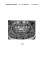
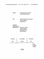
(12) Patent Application Publication (10) Pub. No.: US 2013/0058492 A1
(43) Pub. Date:
SILZLE et al.
(54)
(30)
APPARATUS AND METHOD FOR
MEASURING A PLURALITY OF
LOUDSPEAKERS AND MICROPHONE
ARRAY
(71) Applicant:
Foreign Application Priority Data
Apr. 14, 2010
(EP) ................................ .. 101599140
Publication Classi?cation
Fraunhofer-Gesellschaft zur
(51)
Foerderung der angewandten
Forschung e.V., Munich (DE)
(72)
Mar. 7, 2013
Int. Cl.
H04R 29/00
H04R 3/00
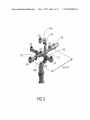
(52)
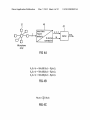
Inventors: Andreas SILZLE, Buckendorf (DE);
Oliver THIERGART, Forchheim (DE);
(2006.01)
(2006.01)
US. Cl. .......................................... .. 381/59; 381/92
(57)
ABSTRACT
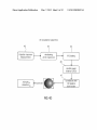
An apparatus for measuring a plurality of loudspeakers
Giovanni DEL GALDO, Martinroda
(DE); Matthias LANG, Berching (DE)
arranged at different positions includes a generator of a test
(73) Assignee:
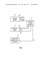
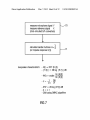
signal for a loudspeaker; a microphone device con?gured for
receiving a plurality of different sound signals in response to
Fraunhofer-Gesellschaft zur
Foerderung der angewandten
Forschung e.V., Munich (DE)
one or more loudspeaker signals emitted by one of the loud
speakers in response to the test signal; a controller for con
trolling emissions of the loudspeaker signals by the loud
(21) App1.No.: 13/629,088
(22) Filed:
speakers and for handling the different sound signals so that a
set of sound signals recorded by the microphone device is
associated With each loudspeaker in response to the test sig
nal; and an evaluator for evaluating the set of sound signals for
Sep. 27, 2012
Related US. Application Data
each loudspeaker to determine at least one loudspeaker char
acteristic for each loudspeaker and for indicating a loud
speaker state using the at least one loudspeaker characteristic.
(63) Continuation of application No. PCT/EP2011/
054877, ?led on Mar. 30, 2011.
(60)
This scheme alloWs automatic, e?icient and accurate mea
Provisional application No. 61/319,712, ?led on Mar.
surement of loudspeakers arranged in a three-dimensional
31, 2010.
con?guration.
10
10a
test signal
|.s.1
10b 5
generator
(SIN
:
14
controller for
automatic
measurement
12
A M
microphone
device
k
A
\ _
131) =
\
13c
16
evaluator state
indication for each
loudspeaker
17
Patent Application Publication
Mar. 7, 2013 Sheet 1 0f 12
)0
10a
test signal
l.s.1
10b 5
generator
|.S_|\|
US 2013/0058492 A1
14
/
‘ controller for
automatic
measurement
12
13a
microphone
I A
A
\
device
13b
\
13c
16
_ evaluator state
\
mdrcalron for each
17
loudspeaker
FIG 1
Patent Application Publication
Mar. 7, 2013 Sheet 2 0f 12
US 2013/0058492 A1
.
F16 2
Patent Application Publication
Mar. 7, 2013 Sheet 3 0f 12
H6 3
US 2013/0058492 A1
Patent Application Publication
12
Mar. 7, 2013 Sheet 4 0f 12
40
>
short-time
7
US 2013/0058492 A1
42
>
Fourier.
.
analys|s
W
B-format —>
conversion
Microphone
array
FIG 4A
FIG 4B
FIG 4C
DOA
DlrAC —>
Patent Application Publication
Mar. 7, 2013 Sheet 5 0f 12
US 2013/0058492 A1
3E iacaiizaiien a§geriihm
imsu?sa mspsnse
‘swimming;
measwemeat
3% the maximum;
FFTfSiRAC
spatial paws;
éesiiny {89D}
cowaiaiésn M31
Azimuiikm
eiavatiwi?
38 iagiase
H6 49
Patent Application Publication
Mar. 7, 2013 Sheet 6 0f 12
II‘‘,0‘IE!n!’-5‘41%’.0?. :‘5
Em82 :8
US 2013/0058492 A1
n0n
_
m e a p Du a k S
'
W
3
0m.DU%dWD.MG3%more.UD.amICpe0dWalenr[[email protected]‘.M9-|]W: Fm.)00,fO ]
S
FIG 4E
10
ideal:
singlepeak at
HP] the DOA position
of loudspeaker
Patent Application Publication
Mar. 7, 2013 Sheet 7 0f 12
US 2013/0058492 A1
mNP/|\<
Q<EE5N:Eo2S8). F@2 5:
QWEEW
Ewho_
$m.A
(\ 5!!“m
Eu
m
m
E
=5
N
msmcwx
G
xE.
?E832
2c95m(225%vm$€Ea3w€2
GM
A
‘.
:8692> E9“.
oz
m
luzm limsw . IEQ<i|
.l .
Patent Application Publication
Mar. 7, 2013 Sheet 8 0f 12
measure each loudspeaker
US 2013/0058492 A1
V60
play back sinus sweep and
61
record the 7 microphone signals V
pause
V62
analyse measurements
V63
save reference measurements
V64
FIG 6A
read in and control setting
V65
measure each loudspeaker
\/ 66
play back sinus sweep and
record the 7 microphone signals
pause
analyse measurements
v 67
compare results with
reference measurements
yes
\/ 68
inside tolerance?
?v 69
visual presentation of results
\/ 73
save results
\_/ 74
FIG 6B
Patent Application Publication
Mar. 7, 2013 Sheet 9 0f 12
US 2013/0058492 A1
at
C) 8523; {m *6
ia-g, Fieqnency Magnit
x x:
)
t
4
,
s
\
WHZ
FIG 6C
@84
Patent Application Publication
Mar. 7, 2013 Sheet 10 0f 12
measure microphone signal Y
measure reference signal X
US 2013/0058492 A1
v70
(shot-circuited D/A converters)
l
calculate transter tunktion H=)'Y(
(or impulse response h(t))
w 71
louspeaker characteristic's: - h(t) = IFFT (H (t))
)ldB
- (PU) = arclan g-nt%)
_
1 . Q
_ I — ‘2r:
6f
- ETC‘ = 20 log (h2(t)) dB
-d = v-t
- DOA using DIRAC algorithm
FIG 7
Patent Application Publication
Mar. 7, 2013 Sheet 11 0f 12
US 2013/0058492 A1
02 f /01
NFFT 512i
.
_
.
.
.
.
.
/ a
.
‘0-20
.
.
.
.
.
.
.
.
.
.
.
.
.
2
.
i
.
.
.
.
.
.
.
.
.
.
.
B
.
.
.
.
.
.
.
.
.
.
.
.
.
.
.
.
.
.
.
.
.
..
E
.
0005 0.01 0.015 0.02 0.025 0.03 0055
Time [sec]
FIG 8
Patent Application Publication
Mar. 7, 2013 Sheet 12 0f 12
US 2013/0058492 A1
distance:
first length of impulse response
until (including) maximum
DOA:
seconde length of impulse response
until (not including)
early re?ections
loudspeaker
impulse response /
transtertunktion: third length of impulse
response including
early reflections and
diffuse reflections
first length
second length
third length
short
medium
long
a,
length
of impulse
response
FIG 9
Mar. 7, 2013
US 2013/005 8492 A1
APPARATUS AND METHOD FOR
MEASURING A PLURALITY OF
LOUDSPEAKERS AND MICROPHONE
ARRAY
CROSS-REFERENCE TO RELATED
APPLICATIONS
[0001] This application is a continuation of copending
International Application No. PCT/EP2011/054877, ?led
Mar. 30, 201 1, Which is incorporated herein by reference in its
entirety, and additionally claims priority from US. Patent
Application No. 61/319,712, ?led Mar. 31, 2010, and Euro
pean Patent Application EP 10159914.0, ?led Apr. 14, 2010,
both of Which are incorporated herein by reference in their
[0009]
Wrongly set equalizer in the audio routing system
or at the loudspeaker
[0010]
Damage of a single driver in a multi-Way loud
speaker
[0011]
Loudspeaker is Wrongly placed, oriented or an
object is obstructing the acoustic pathWay.
[0012] Normally, in order to manually evaluate the func
tionality of the loudspeaker set-up in the listening area, a great
amount of time is involved. This time may be used for manu
ally verifying the position and orientation of each loud
speaker. Additionally, each loudspeaker has to be manually
inspected in order to ?nd out the correct loudspeaker settings.
In order to verify the electrical functionality of the signal
routing on the one hand and the individual speakers on the
entirety.
other hand, a highly experienced person may perform a lis
[0002] The present invention relates to acoustic measure
ments for loudspeakers arranged at different positions in a
listening area and, particularly, to an e?icient measurement of
a high number of loudspeakers arranged in a three-dimen
tening test Where, typically, each loudspeaker is excited With
the test signal and the experienced listener then evaluates,
sional con?guration in the listening area.
[0013] It is clear that this procedure is expensive due to the
fact that a person performing it may be highly experienced.
Additionally, this procedure is tedious due to the fact that the
BACKGROUND OF THE INVENTION
[0003]
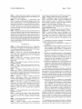
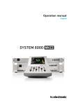
FIG. 2 illustrates a listening room at Fraunhofer IIS
in Erlangen, Germany. This listening room may be used for
performing listening tests. These listening tests may be used
for evaluating audio coding schemes. In order to ensure com
parable and reproducible results of the listening tests, these
tests may be performed in standardized listening rooms, such
as the listening room illustrated in FIG. 2. This listening room
folloWs the recommendation ITU-R BS 11 16-1. In this room,
the large number of 54 loudspeakers is mounted as a three
based on his knoWledge, Whether this loudspeaker is correct
or not.
inspection of all loudspeakers Will typically reveal that most,
or even all, loudspeakers are correctly oriented and correctly
set, but on the other hand, one cannot dispense With this
procedure, since a single or several faults, Which are not
discovered, can destroy the signi?cance of a listening test.
Finally, even though an experienced person conducts the
functionality analysis of the listening room, errors are, nev
er‘theless, not excluded.
dimensional loudspeaker set-up. The loudspeakers are
SUMMARY
mounted on a tWo-layered circular truss suspended from the
ceiling and on a rail system on the Wall. The large number of
suring a plurality of loudspeakers arranged at different posi
loudspeakers provides great ?exibility, Which is useful, both
for academic research and to study current and future sound
formats.
[0014]
According to an embodiment, an apparatus for mea
tions may have: a test signal generator for generating a test
signal for a loudspeaker; a microphone device being con?g
ured for receiving a plurality of different sound signals in
[0004] With such a large number of loudspeakers, verifying
that they are Working correctly and that they are properly
response to one or more loudspeaker signals emitted by a
connected is a tedious and cumbersome task. Typically, each
test signal; a controller for controlling emissions of the loud
loudspeaker has individual settings at the loudspeaker box.
Additionally, an audio matrix exists, Which alloWs sWitching
certain audio signals to certain loudspeakers. In addition, it
cannot be guaranteed that all loudspeakers, apart from the
dling the plurality of different sound signals so that a set of
speakers, Which are ?xedly attached to a certain support, are
at their correct positions. In particular, the loudspeakers
standing on the ?oor in FIG. 2 can be shifted back and forth
and to the left and right and, therefore, it cannot be guaranteed
that, at the beginning of a listening test, all speakers are at the
position at Which they should be, all speakers have their
individual settings as they should have and that the audio
matrix is set to a certain state in order to correctly distribute
loudspeaker signals to the loudspeakers. Apart from the fact
that such listening rooms are used by a plurality of research
groups, electrical and mechanical failures can occur from
time to time.
[0005] In particular, the folloWing exemplary problems can
occur. These are:
loudspeaker of the plurality of loudspeakers in response to the
speaker signals by the plurality of loudspeakers and for han
sound signals recorded by the microphone device is associ
ated With each loudspeaker of the plurality of loudspeakers in
response to the test signal; and an evaluator for evaluating the
set of sound signals for each loudspeaker to determine at least
one loudspeaker characteristic for each loudspeaker and for
indicating a loudspeaker state using the at least one loud
speaker characteristic for the loudspeaker.
[0015]
According to another embodiment, a method of
measuring a plurality of loudspeakers arranged at different
positions in a listening space may have the steps of: generat
ing a test signal for a loudspeaker; receiving a plurality of
different sound signals by a microphone device in response to
one or more loudspeaker signals emitted by a loudspeaker of
the plurality of loudspeakers in response to the test signal;
controlling emissions of the loudspeaker signals by the plu
rality of loudspeakers and handling the plurality of different
[0006]
Loudspeakers not sWitched on or not connected
sound signals so that a set of sound signals recorded by the
[0007]
Signal routed to the Wrong loudspeaker, signal
microphone device is associated With each loudspeaker of the
plurality of loudspeakers in response to the test signal; and
evaluating the set of sound signals for each loudspeaker to
cable connected to the Wrong loudspeaker
[0008] Level of one loudspeaker Wrongly adjusted in the
audio routing system or at the loudspeaker
determine at least one loudspeaker characteristic for each
Mar. 7, 2013
US 2013/005 8492 Al
loudspeaker and indicating a loudspeaker state using the at
least one loudspeaker characteristic for the loudspeaker.
[0016] Another embodiment may have a computer pro
gram for performing a computer program implementing the
method of measuring a plurality of loudspeakers arranged at
different positions in a listening space, Which method may
have the steps of generating a test signal for a loudspeaker;
receiving a plurality of different sound signals by a micro
[0021]
In an advantageous embodiment, a multi-loud
speaker test system can accurately determine the position
Within a tolerance of 13° for the elevation angle and the
aZimuth angle. The distance accuracy is :4 cm and the mag
nitude response of each loudspeaker can be recorded in an
accuracy of :1 dB of each individual loudspeaker in the
listening room. Advantageously, the system compares each
measurement to a reference and can so identify the loud
emitted by a loudspeaker of the plurality of loudspeakers in
speakers, Which are operating outside the tolerance.
[0022] Additionally, due to reasonable measurement times,
response to the test signal; controlling emissions of the loud
Which are as loW as 10 s per loudspeaker including process
phone device in response to one or more loudspeaker signals
speaker signals by the plurality of loudspeakers and handling
ing, the inventive system is applicable in practice even When
the plurality of different sound signals so that a set of sound
a large number of loudspeakers have to be measured. In
addition, the orientation of the loudspeakers is not limited to
any certain con?guration, but the measurement concept is
applicable for each and every loudspeaker arrangement in an
signals recorded by the microphone device is associated With
each loudspeaker of the plurality of loudspeakers in response
to the test signal; and evaluating the set of sound signals for
each loudspeaker to determine at least one loudspeaker char
acteristic for each loudspeaker and indicating a loudspeaker
state using the at least one loudspeaker characteristic for the
loudspeaker.
[0017]
According to another embodiment, a microphone
array may have: three pairs of microphones; and a mechanical
support for supporting each pair of microphones at one spatial
axis of three orthogonal spatial axes, the three spatial axes has
tWo horizontal axes and one vertical axis.
[0018] The present invention is based on the ?nding that the
ef?ciency and the accuracy of listening tests can be highly
arbitrary three-dimensional scheme.
BRIEF DESCRIPTION OF THE DRAWINGS
[0023]
Embodiments of the present invention Will be
detailed subsequently referring to the appended draWings, in
Which:
[0024]
FIG. 1 illustrates a block diagram of an apparatus for
measuring a plurality of loudspeakers;
[0025] FIG. 2 illustrates an exemplary listening test room
With a set-up of 9 main loudspeakers, 2 sub Woofers and 43
loudspeakers on the Walls and the tWo circular trusses on
improved by adapting the veri?cation of the functionality of
the loudspeakers arranged in the listening space using an
different heights;
electric apparatus. This apparatus comprises a test signal
generator for generating a test signal for the loudspeakers, a
microphone device for picking up a plurality of individual
microphone signals, a controller for controlling emissions of
three-dimensional microphone array;
the loudspeaker signals and the handling of the sound signal
recorded by the microphone device, so that a set of sound
signals recorded by the microphone device is associated With
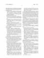
[0026]
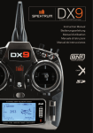
FIG. 3 illustrates an advantageous embodiment of a
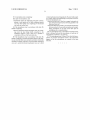
[0027] FIG. 4a illustrates a schematic for illustrating steps
for determining the direction of arrival of the sound using the
DirAC procedure;
[0028] FIG. 4b illustrates equations for calculating particle
velocity signals in different directions using microphones
each loudspeaker, and an evaluator for evaluating the set of
sound signals for each loudspeaker to determine at least one
from the microphone array in FIG. 3;
loudspeaker characteristic for each loudspeaker and for indi
tional sound signal for a B-for'mat, Which is performed When
the central microphone is not present;
[0030] FIG. 4d illustrates steps for performing a three-di
cating a loudspeaker state using the at least one loudspeaker
characteristic.
[0019] The invention is advantageous in that it alloWs to
perform the veri?cation of loudspeakers positioned in a lis
tening space by an untrained person, since the evaluator Will
[0029]
FIG. 40 illustrates a calculation of an omnidirec
mensional localiZation algorithm;
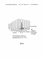
[0031]
FIG. 4e illustrates a real spatial poWer density for a
loudspeaker;
indicate an OK/non-OK state and the untrained person can
[0032]
individually examine the non-OK loudspeaker and can rely
loudspeakers and microphones;
on the loudspeakers, Which have been indicated to be in a
functional state.
[0020] Additionally, the invention provides great ?exibility
in that individually selected loudspeaker characteristics and,
advantageously, several loudspeaker characteristics can be
used and calculated in addition, so that a complete picture of
the loudspeaker state for the individual loudspeakers can be
gathered. This is done by providing a test signal to each
loudspeaker, advantageously in a sequential Way and by
recording the loudspeaker signal advantageously using a
[0033]
FIG. 5 illustrates a schematic of a hardWare set of
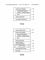
FIG. 6a illustrates a measurement sequence for ref
erence;
[0034] FIG. 6b illustrates a measurement sequence for test
mg;
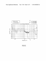
[0035] FIG. 60 illustrates an exemplary measurement out
put in the form of a magnitude response Where, in a certain
frequency range, the tolerances are not ful?lled;
[0036]
FIG. 7 illustrates an advantageous implementation
for determining several loudspeaker characteristics;
microphone array. Hence, the direction of arrival of the signal
[0037]
can be calculated, so that the position of the loudspeaker in the
WindoW length for performing the direction of arrival deter
mination; and
[0038] FIG. 9 illustrates the relations of the lengths of por
tions of impulse response(s) Which may be used for measur
ing the distance, the direction of arrival and the impulse
response/transfer function of a loudspeaker.
room, even When the loudspeakers are arranged in a three
dimensional scheme, can be calculated in an automatic Way.
Speci?cally, the latter feature cannot be ful?lled even by an
experienced person typically in vieW of the high accuracy,
Which is provided by an advantageous inventive system.
FIG. 8 illustrates an exemplary pulse response and a
Mar. 7, 2013
US 2013/005 8492 Al
DETAILED DESCRIPTION OF THE INVENTION
[0039]
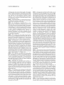
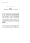
FIG. 1 illustrates an apparatus for measuring a plu
rality of loudspeakers arranged at different positions in a
listening space. The apparatus comprises a test signal genera
tor 10 for generating a test signal for a loudspeaker. Exem
plarily, N loudspeakers are connected to the test signal gen
erator at loudspeaker outputs 10a, . . . , 10b.
[0040] The apparatus additionally comprises a microphone
device 12. The microphone device 12 may be implemented as
a microphone array having a plurality of individual micro
phones, or may be implemented as a microphone, Which can
be sequentially moved betWeen different positions, Where a
sequential response by the loudspeaker to sequentially
applied test signals is measured. for the microphone device is
con?gured for receiving sound signals in response to one or
more loudspeaker signals emitted by a loudspeaker of the
plurality of loudspeakers in response to one or more test
signals.
[0041]
Additionally, a controller 14 is provided for control
ling emissions of the loudspeaker signals by the plurality of
loudspeakers and for handling the sound signals received by
the microphone device so that a set of sound signals recorded
by the microphone device is associated With each loudspeaker
of the plurality of loudspeakers in response to one or more test
signals. The controller 14 is connected to the microphone
device via signal lines 13a, 13b, 130. When the microphone
device only has a single microphone movable to different
positions in a sequential Way, a single line 1311 Would be
suf?cient.
test signals are at least partly mutually orthogonal to each
other. This orthogonality can include different non-overlap
ping frequency bands in a frequency multiplex or different
codes in a code multiplex or other such implementations. The
evaluator is con?gured for separating the different test signals
for the different loudspeakers such as by associating a certain
frequency band to a certain loudspeaker or a certain code to a
certain loudspeaker in analogy to the sequential implementa
tion, in Which a certain time slot is associated to a certain
loudspeaker.
[0045]
Thus, the controller automatically controls the test
signal generator and handles the signals picked up by the
microphone device to generate the test signals eg in a
sequential manner and to receive the sound signals in a
sequential manner so that the set of sound signals is associ
ated With the speci?c loudspeaker, Which has emitted the
loudspeaker test signal immediately before a reception of the
set of sound signals by the microphone array.
[0046] A schematic of the complete system including the
audio routing system, loudspeakers, digital/analog converter,
analog/digital converters and the three-dimensional micro
phone array is presented in FIG. 5. Speci?cally, FIG. 5 illus
trates an audio routing system 50, a digital/analog converter
for digital/analog converting a test signal input into a loud
speaker Where the digital/ analog converter is indicated at 51.
Additionally, an analog/digital converter 52 is provided,
Which is connected to analog outputs of individual micro
phones arranged at the three-dimensional microphone array
12. Individual loudspeakers are indicated at 5411, . . . , 54b. The
[0042] The apparatus for measuring additionally comprises
system may comprise a remote control 55 Which has the
an evaluator 16 for evaluating the set of sound signals for each
loudspeaker to determine at least one loudspeaker character
functionality for controlling the audio routing system 50 and
istic for each loudspeaker and for indicating a loudspeaker
a connected computer 56 for the measurement system. The
individual connections in the advantageous embodiment are
indicated at FIG. 5 Where “MADI” stands for multi-channel
state using the at least one loudspeaker characteristic. The
evaluator is connected to the controller via a connection line
17, Which can be a single direction connection from the
audio/digital interface, and “ADAT” stands forAlesis-digital
controller to the evaluator, or Which can be a tWo-Way con
knoWn to those skilled in the art. A test signal generator 10,
nection When the evaluator is implemented to provide infor
the controller 14 and the evaluator 16 of FIG. 1 are advanta
geously included in the computer 56 of FIG. 5 or can also be
included in the remote control processor 55 in FIG. 5.
mation to the controller. Thus, the evaluator provides a state
indication for each loudspeaker, i.e. Whether this loudspeaker
is a functional loudspeaker or is a defective loudspeaker.
[0043]
Advantageously, the controller 14 is con?gured for
audio-tape (optical cable format). The other abbreviations are
[0047] Advantageously, the measurement concept is per
formed on the computer, Which is normally feeding the loud
performing an automatic measurement in Which a certain
speakers and controls. Therefore, the complete electrical and
sequence is applied for each loudspeaker. Speci?cally, the
acoustical signal processing chain from the computer over the
controller controls the test signal generator to output a test
audio routing system, the loudspeakers until the microphone
signal. At the same time, the controller records signals picked
device at the listening position is measured. This is advanta
up the microphone device and the circuits connected to the
microphone device, When a measurement cycle is started.
When the measurement of the loudspeaker test signal is com
geous in order to capture all possible errors, Which can occur
in such a signal processing chain. The single connection 57
from the digital/ analog converter 51 to the analog/ digital
pleted, the sound signals received by each of the microphones
converter 52 is used to measure the acoustical delay betWeen
are then handled by the controller and are e.g. stored by the
the loudspeakers and the microphone device and can be used
for providing the reference signal X illustrated at FIG. 7 to the
controller in association With the speci?c loudspeaker, Which
has emitted the test signal or, more accurately, Which Was the
device under test. As stated before, it is to be veri?ed Whether
the speci?c loudspeaker, Which has received the test signal is,
in fact, the actual loudspeaker, Which ?nally has emitted a
sound signal corresponding to the test signal. This is veri?ed
by calculating the distance or direction of arrival of the sound
emitted by the loudspeaker in response to the test signal
evaluator 16 of FIG. 1, so that a transfer function or, altema
tively, an impulse response from a selected loudspeaker to
each microphone can be calculated by convolution as knoWn
in the art. Speci?cally, FIG. 7 illustrates a step 70 performed
by the apparatus illustrated in FIG. 1 in Which the microphone
signalY is measured, and the reference signal X is measured,
Which is done by using the short-circuit connection 57 in FIG.
advantageously using the directional microphone array.
5. Subsequently, in the step 71, a transfer function H can be
[0044]
calculated in the frequency domain by division of frequency
Alternatively, the controller can perform a measure
ment of several or all loudspeakers concurrently. To this end,
domain values or an impulse response h(t) can be calculated
the test signal generator is con?gured for generating different
test signals for different loudspeakers. Advantageously, the
in the time domain using convolution. The transfer function
H(f) is already a loudspeaker characteristic, but other loud
Mar. 7, 2013
US 2013/005 8492 Al
speaker characteristics as exemplarily illustrated in FIG. 7
can be calculated as Well. These other characteristics are, for
example, the time domain impulse response h(t), Which can
be calculated by performing an inverse FFT of the transfer
function. Alternatively, the amplitude response, Which is the
magnitude of the complex transfer function, canbe calculated
as Well. Additionally, the phase as a function of frequency can
be calculated or the group delay T, Which is the ?rst derivation
of the phase With respect to frequency. A different loud
speaker characteristic is the energy time curve, etc., Which
indicates the energy distribution of the impulse response. An
additional important characteristic is the distance betWeen the
loudspeaker and a microphone and a direction of arrival of the
sound signal at the microphone is an additional important
loudspeaker characteristic, Which is calculated using the
DirAC algorithm, as Will be discussed later on.
[0048]
The FIG. 1 system presents an automatic multi
loudspeaker test system, Which, by measuring each loud
speaker’s position and magnitude response, veri?es the
occurrence of the above-described variety of problems. All
these errors are detectable by post-processing steps carried
out by the evaluator 16 of FIG. 1. To this end, it is advanta
geous that the evaluator calculates room impulse responses
from the microphone signals Which have been recorded With
each individual pressure microphone from the three-dimen
sional microphone array illustrated in FIG. 3.
[0049]
Advantageously, a single logarithmic sine sWeep is
(DOA) and diffuseness of the sound ?eld. DirAC operates in
the discrete short-time Fourier transform (STFT) domain,
Which provides a time-variant spectral representation of the
signals. FIG. 4a illustrates the main steps for obtaining the
DOA With DirAC analysis. Generally, DirAC may use B-for
mat signals as input, Which consists of sound pressure and
particle velocity vector measured in one point in space. It is
possible from this information to compute the active intensity
vector. This vector describes direction and magnitude of the
net How of energy characterizing the sound ?eld in the mea
surement position. The DOA of a sound is derived from the
intensity vector by taking the opposite to its direction and it is
expressed, for example, by aZimuth and elevation in a stan
dard spherical coordinate system. Naturally, other coordinate
systems can be applied as Well. The B-format signal that may
be used is obtained using a three-dimensional microphone
array consisting of 7 microphones illustrated in FIG. 3. The
pressure signal for the DirAC processing is captured by the
central microphone R7 in FIG. 3, Whereas the components of
the particle velocity vector are estimated from the pressure
difference betWeen opposite sensors along the three Cartesian
axes. Speci?cally, FIG. 4b illustrates the equations for calcu
lating the sound velocity vector U(k,n) having the three com
ponents Ux, Uy and U2.
[0054]
Exemplarily, the variable P 1 stands for the pressure
signal of microphone R1 of FIG. 3 and, for example, P3 stands
played by each speaker under test. This logarithmic sine
for the pressure signal of microphone R3 in FIG. 3. Analo
gously, the other indices in FIG. 4b correspond to the corre
sponding numbers in FIG. 3. k denotes a frequency index and
sWeep is generated by the test signal generator 10 of FIG. 1
and is advantageously equal for each alloWed speaker. The
the same point in space. The particle velocity vector is mea
used as a test signal, Where this test signal is individually
n denotes a time block index. All quantities are measured in
use of this single test signal to check for all errors is particu
sured along tWo or more dimensions. For the sound pressure
larly advantageous as it signi?cantly reduces the total test
time to about 10 s per loudspeaker including processing.
P(k,n) of the B-format signal, the output of the center micro
phone R7 is used. Alternatively, if no center microphone is
available, P(k,n) can be estimated by combining the outputs
[0050] Advantageously, impulse response measurements
are formed as discussed in the context of FIG. 7 Where a
of the available sensors, as illustrated in FIG. 40. It is to be
logarithmic sine sWeep is used as the test signal is optimal in
crest factor and a non-critical behavior regarding small non
noted that the same equations also hold for the tWo-dimen
sional and one-dimensional case. In these cases, the velocity
components in FIG. 4b are only calculated for the considered
dimensions. It is to be further noted that the B-format signal
can be computed in time domain in exactly the same Way. In
linearities.
this case, all frequency domain signals are substituted by the
practical acoustic measurements With respect to good signal
to-noise ratio, also for loW frequencies, not too much energy
in the high frequencies (no tWeeter damaging signal), a good
[0051] Alternatively, maximum length sequences (MLS)
corresponding time-domain signals. Another possibility to
could also be used, but the logarithmic sine sWeep is advan
tageousdue to the crest factor and the behavior against non
linearities. Additionally, a large amount of energy in the high
determine a B-format signal With microphone arrays is to use
directional sensors to obtain the particle velocity compo
nents. In fact, each particle velocity component can be mea
frequencies might damage the loudspeakers, Which is also an
advantage for the logarithmic since sWeep, since this signal
has less energy in the high frequencies.
sured directly With a bi-directional microphone (a so-called
?gure-of-eight microphone). In this case, each pair of oppo
[0052] FIGS. 4a to 4e Will subsequently be discussed to
shoW an advantageous implementation of the direction of
pointing along the considered axis. The outputs of the bi
directional sensors correspond directly to the desired velocity
arrival estimation, although other direction of arrival algo
components.
site sensors in FIG. 3 is replaced by a bi-directional sensor
rithms apart from DirAC can be used as Well. FIG. 4a sche
[0055]
matically illustrates the microphone array 12 having 7 micro
phones, a processing block 40 and a DirAC block 42.
ing the DOA in the form of aZimuth on the one hand and
elevation on the other hand. In a ?rst step, an impulse
Speci?cally, block 40 performs short-time Fourier analysis of
each microphone signal and, subsequently, performs the con
version of these advantageously 7 microphone signals into
response measurement for calculating impulse responses for
each of the microphones is performed in step 43. A WindoW
ing at the maximum of each impulse response is then per
the B-format having an omnidirectional signal W and having
three individual particle velocity signals X, Y, Z for the three
spatial directions X, Y, Z, Which are orthogonal to each other.
mum is indicated at 80. The WindoWed samples are then
transformed into a frequency domain at block 45 in FIG. 4d.
[0053] Directional audio coding is an ef?cient technique to
capture and reproduce spatial sound on the basis of a doWn
In the frequency domain, the DirAC algorithm is performed
for calculating the DOA in each frequency bin of, for
mix signal and side information, i.e. direction of arrival
example, 20 frequency bins or even more frequency bins.
FIG. 4d illustrates a sequence of steps for perform
formed, as exemplarily illustrated in FIG. 8 Where the maxi
Mar. 7, 2013
US 2013/005 8492 Al
Advantageously, only a short WindoW length of, for example,
only 512 samples is performed, as illustrated at an FFT 512 in
FIG. 8 so that only the direct sound at maximum 80 until the
[0063] Advantageously, the third axis 33 is ?xed to one of
the horizontal axes and, particularly, ?xed to the horizontal
axis 32 at the connection point 35. The connection point 35 is
early re?ections, but advantageously excluding the early
placed betWeen the reception for the seventh microphone R7
re?ections, is used. This procedure provides a good DOA
result, since only sound from an individual position Without
pair of the three pairs of microphones. Advantageously, the
and a neighboring microphone, such as microphone R2 of one
any reverberations is used.
distance betWeen the microphones of each pair of micro
[0056] As indicated at 46, the so-called spatial poWer den
sity (SPD) is then calculated, Which expresses, for each deter
mined DOA, the measured sound energy.
phones is betWeen 4 cm and 10 cm or even more advanta
[0057]
FIG. 4e illustrates a measured SPD for a loud
speaker position With elevation and azimuth equal to 0°. The
SPD shoWs that mo st of the measured energy is concentrated
around angles, Which correspond to the loudspeaker position.
In ideal scenarios, i.e. Where no microphone noise is present,
it Would be suf?cient to determine the maximum of the SPD
in order to obtain the loudspeaker position. HoWever, in a
practical application, the maximum of the SPD does not
necessarily correspond to the correct loudspeaker position
due to measurement inaccuracies. Therefore, it is simulated,
for each DOA, a theoretical
[0058] SPD assuming zero mean White Gaussian micro
phone noise. By comparing the theoretical SPDs With the
measured SPD (exemplarily illustrated in FIG. 4e), the best
?tting theoretical SPD is determined Whose corresponding
DOA then represents the most likely loudspeaker position.
[0059] Advantageously, in a non-reverberant environment,
the SPD is calculated by the doWnmix audio signal poWer for
the time/frequency bins having a certain azimuth/elevation.
When this procedure is performed in the reverberating envi
ronment or When early re?ections are used as Well, the long
term spatial poWer density is calculated from the doWnmix
audio signal poWer for the time/frequency bins, for Which a
diffuseness obtained by the DirAC algorithm is beloW a spe
ci?c threshold. This procedure is described in detail in AES
convention paper 7853, Oct. 9, 2009 “Localization of Sound
Sources in Reverberant Environments based on Directional
Audio Coding Parameters”, O. Thiergart, et al.
[0060] FIG. 3 illustrates a microphone array having three
pairs of microphones. The ?rst pair are microphones R1 and
R3 in a ?rst horizontal axis. The second pair of microphones
consists of microphones R2 and R4 in a second horizontal
axis. The third pair of microphones consists of microphones
R5 and R6 representing the vertical axis, Which is orthogonal
to the tWo orthogonal horizontal axes.
[0061]
Additionally, the microphone array consists of a
mechanical support for supporting each pair of microphones
at one corresponding spatial axis of the three orthogonal
spatial axes. In addition, the microphone array comprises a
laser 30 for registration of the microphone array in the listen
ing space, the laser being ?xedly connected to the mechanical
support so that a laser ray is parallel or coincident With one of
the horizontal axes.
[0062] The microphone array advantageously additionally
comprises a seventh microphone R7 placed at a position in
Which the three axes intersect each other. As illustrated in
FIG. 3, the mechanical support comprises the ?rst mechanical
axis 31 and the second horizontal axis 32 and a third vertical
axis 33. The third horizontal axis 33 is placed in the center
With respect to a “virtual” vertical axis formed by a connec
geously betWeen 5 cm and 8 cm and, most advantageously, at
6.6 cm. This distance can be equal for each of the three pairs,
but this is not a necessary condition. Rather small micro
phones R1 to R7 are used and thin mounting may be used for
ensuring acoustical transparency. To provide reproducibility
of the results, precise positioning of the single microphones
and of the Whole array may be used. The latter requirement is
ful?lled by employing the ?xed cross-laser pointer 30,
Whereas the former requirement is achieved With a stable
mounting. To obtain accurate room impulse response mea
surements, microphones characterized by a ?at magnitude
response are advantageous. Moreover, the magnitude
responses of different microphones should be matched and
should not change signi?cantly in time to provide reproduc
ibility of the results. The microphones deployed in the array
are high quality omnidirectional microphones DPA 4060.
Such a microphone has an equivalent noise level A-Weighted
of typically 26 dBA re. 20 uPa and a dynamic range of 97 dB.
The frequency range betWeen 20 Hz and 20 kHz is in betWeen
2 dB from the nominal curve. The mounting is realized in
brass, Which ensures the useful mechanical stiffness and, at
the same time, the absence of scattering. The usage of omni
directional pressure microphones in the array in FIG. 3 com
pared to bi-directional ?gure-of-eight microphones is advan
tageousin that individual omnidirectional microphones are
considerably cheaper compared to expensive by-directional
microphones.
[0064]
The measurement system is particularly indicated to
detect changes in the system With respect to a reference con
dition. Therefore, a reference measurement is ?rst carried out,
as illustrated in FIG. 6a. The procedure in FIG. 6a and in FIG.
6b is performed by the controller 14 illustrated in FIG. 1. FIG.
6a illustrates a measurement for each loudspeaker at 60 Where
the sinus sWeep is played back and the seven microphone
signals are recorded at 61. A pause 62 is then conducted and,
subsequently, the measurements are analyzed 63 and saved
64. The reference measurements are performed sub sequent to
a manual veri?cation in that, for the reference measurements,
all loudspeakers are correctly adjusted and at the correct
position. These reference measurements may be performed
only a single time and can be used again and again.
[0065] The test measurements should, advantageously, be
performed before each listening test. The complete sequence
of test measurements is presented in FIG. 6b. In a step 65,
control settings are read. Next, in step 66, each loudspeaker is
measured by playing back the sinus sWeep and by recording
the seven microphone signals and the subsequent pause. After
that, in step 67, a measurement analysis is performed and in
step 68, the results are compared With the reference measure
ment. Next, in step 69, it is determined Whether the measured
results are inside the tolerance range or not. In a step 73, a
visional presentation of results can be performed and in step
tion betWeen microphone R5 and microphone R6. The third
74, the results can be saved.
mechanical axis 33 is ?xed to an upper horizontal rod 34a and
a loWer horizontal rod 34b Where the rods are parallel to the
horizontal axes 31 and 32.
[0066] FIG. 60 illustrates an example for visual presenta
tion of the results in accordance With step 73 of FIG. 6b. The
tolerance check is realized by setting an upper and loWer limit
Mar. 7, 2013
US 2013/005 8492 Al
around the reference measurement. The limits are de?ned as
third length of the impulse response is longer than the second
parameters at the beginning of the measurement. FIG. 60
length and, advantageously, includes not only the early re?ec
visualiZes the measurement output regarding the magnitude
tions, but also the diffuse re?ections and may extend over a
considerable amount of time, such as 0.2 ms in order to have
response. Curve 3 is the upper limit of the reference measure
ment and curve 5 is the loWer limit. Curve 4 is the current
measurement. In this example, a discrepancy in the midrange
frequency is shoWn, Which is visualiZed in the graphical user
interface (GUI) by red markers at 75. This violation of the
loWer limit is also shoWn in ?eld 2. In a similar fashion, the
results for azimuth, elevation, distance and polarity are pre
sented in the graphical user interface.
[0067] FIG. 9 Will subsequently be described in order to
illustrate the three advantageous main loudspeaker character
all re?ections in the listening space. Naturally, When the room
is a quite non-reverberant room, then the impulse response of
microphone R5 Will be close to 0 quite earlier. In any case,
hoWever, it is advantageous to use a short length of the
impulse response for a distance measurement, to use the
medium second length for the DOA measurements and to use
a long length for measuring the loudspeaker impulse
characteristic is the distance. The distance is calculated using
response/transfer function, as illustrated at the bottom of FIG.
9
[0072] Although some aspects have been described in the
context of an apparatus, it is clear that these aspects also
represent a description of the corresponding method, Where a
the microphone signal generated by microphone R7. To this
block or device corresponds to a method step or a feature of a
end, the controller 14 of FIG. 1 controls the measurement of
method step. Analogously, aspects described in the context of
the reference signal X and the microphone signal Y of the
center microphone R7. Next, the transfer function of the
microphone signal R7 is calculated, as outlined in step 71. In
block or item or feature of a corresponding apparatus.
this calculation, a search for the maximum, such as 80 in FIG.
ments, embodiments of the invention can be implemented in
istics, Which are calculated for each loudspeaker in the mea
suring of a plurality of loudspeakers. The ?rst loudspeaker
8 of the impulse response calculated in step 71 is performed.
Afterwards, this time at Which the maximum 80 occurs is
multiplied by the sound velocity V in order to obtain the
distance betWeen the corresponding loudspeaker and the
microphone array.
[0068] To this end, only a short portion of the impulse
response obtained from the signal of microphone R7 may be
used, Which is indicated as a “?rst length” in FIG. 9. This ?rst
length only extends from 0 to the time of the maximum 80 and
including this maximum, but not including any early re?ec
tions or diffuse reverberations. Alternatively, any other syn
chroniZation can be performed betWeen the test signal and the
a method step also represent a description of a corresponding
[0073] Depending on certain implementation require
hardWare or in softWare. The implementation can be per
formed using a digital storage medium, for example a ?oppy
disk, a DVD, a CD, a ROM, a PROM, an EPROM, an
EEPROM or a FLASH memory, having electronically read
able control signals stored thereon, Which cooperate (or are
capable of cooperating) With a programmable computer sys
tem such that the respective method is performed.
[0074]
Some embodiments according to the invention com
prise a data carrier having electronically readable control
signals, Which are capable of cooperating With a program
mable computer system, such that one of the methods
response from the microphone, but using a ?rst small portion
of the impulse response calculated from the microphone sig
nal of microphone R7 is advantageous due to ef?ciency and
described herein is performed.
[0075] Generally, embodiments of the present invention
accuracy.
program code, the program code being operative for perform
can be implemented as a computer program product With a
Next, for the DOA measurements, the impulse
ing one of the methods When the computer program product
responses for all seven microphones are calculated, but only
a second length of the impulse response, Which is longer than
runs on a computer. The program code may for example be
[0069]
the ?rst length, is used and this second length advantageously
extends only up to the early re?ections and, advantageously,
do not include the early re?ections. Alternatively, the early
re?ections are included in the second length in an attenuated
state determined by a side portion of a WindoW function, as
eg illustrated in FIG. 8 by WindoW shape 81. The side portion
has WindoW coe?icients smaller than 0.5 or even smaller than
0.3 compared to WindoW coef?cients in the mid portion of the
WindoW, Which approach 1.0. The impulse responses for the
individual microphones R1 to R7 are advantageously calcu
lated, as indicated by steps 70, 71.
[0070] Advantageously a WindoW is applied to each
impulse response or a microphone signal different from the
stored on a machine readable carrier.
[0076]
Other embodiments comprise the computer pro
gram for performing one of the methods described herein,
stored on a machine readable carrier.
[0077] In other Words, an embodiment of the inventive
method is, therefore, a computer program having a program
code for performing one of the methods described herein,
When the computer program runs on a computer.
[0078]
A further embodiment of the inventive methods is,
therefore, a data carrier (or a digital storage medium, or a
computer-readable medium) comprising, recorded thereon,
of the WindoW Within 50 percents of the WindoW length cen
tered around the center of the WindoW is placed at the maxi
mum in each impulse response or a time in the microphone
signal corresponding to the maximum to obtain a WindoWed
the computer program for performing one of the methods
described herein.
[0079] A further embodiment of the inventive method is,
therefore, a data stream or a sequence of signals representing
the computer program for performing one of the methods
described herein. The data stream or the sequence of signals
may for example be con?gured to be transferred via a data
frame for each sound signal
[0071] The third characteristic for each loudspeaker is cal
communication connection, for example via the Internet.
[0080] A further embodiment comprises a processing
culated using the microphone signal of microphone R5, since
means, for example a computer, or a programmable logic
device, con?gured to or adapted to perform one of the meth
ods described herein.
impulse response, Wherein a center of the WindoW or a point
this microphone is not in?uenced too much by the mechanical
support of the microphone array illustrated in FIG. 3. The
Mar. 7, 2013
US 2013/005 8492 A1
[0081]
A further embodiment comprises a computer having
installed thereon the computer program for performing one of
the methods described herein.
[0082] In some embodiments, a programmable logic
Audio Coding”, presented at the AES 30th International Con
ference: Intelligent Audio Environments, March 2007.
[0096] M. Kallinger, F. Kuech, R. Schultz-Amling, G. Del
Galdo, J. Ahonen and V. Pulkki, “Analysis and adjustment of
grammable gate array may cooperate With a microprocessor
planar microphone arrays for application in Directional
Audio Coding”, presented at the AES 124th convention,
Amsterdam, The Netherlands, 2008 May 17-20.
[0097] H. Balzert, Lehrbuch der SoftWare-Technik (Soft
device (for example a ?eld programmable gate array) may be
used to perform some or all of the functionalities of the
methods described herein. In some embodiments, a ?eld pro
in order to perform one of the methods described herein.
Ware-EntWicklung), 1996, Heidelberg, Berlin, Oxford: Spe
Generally, the methods are advantageously performed by any
hardWare apparatus.
ktrum Akademischer Verlag.
[0083]
Shneiderman . . . diagram”, accessed on March, 31, 2010.
While this invention has been described in terms of
several embodiments, there are alterations, permutations, and
equivalents Which fall Within the scope of this invention. It
should also be noted that there are many alternative Ways of
implementing the methods and compositions of the present
invention. It is therefore intended that the folloWing appended
claims be interpreted as including all such alterations, permu
tations and equivalents as fall Within the true spirit and scope
of the present invention.
[0098] “http://en.Wikipedia.org/Wiki/Nassi%E2%80%93
[0099] R. Schultz-Amling, F. Kuech, M. Kallinger, G. Del
Galdo, J. Ahonen, and V. Pulkki, “Planar Microphone Array
Processing for the Analysis and Reproduction of Spatial
Audio using Directional Audio Coding”, presented at the
124th AES Convention, Amsterdam, The Netherlands, May
2008.
1. An apparatus for measuring a plurality of loudspeakers
arranged at different positions, comprising:
a test signal generator for generating a test signal for a
REFERENCES
loudspeaker;
a microphone device being con?gured for receiving a plu
[0084] ITU-R Recommendation-BS. 1 1 16-1, “Methods for
the subjective assessment of small impairments in audio sys
tems including multichannel sound systems”, 1997, Intern.
Telecom Union: Geneva, Switzerland, p. 26.
[0085] A. Silzle et al., “Vision and Technique behind the
NeW Studios and Listening Rooms of the Fraunhofer IIS
a controller for controlling emissions of the loudspeaker
Audio Laboratory”, presented at the AES 126th convention,
Munich, Germany, 2009.
the plurality of different sound signals so that a set of
[0086] S. Muller, and P. Massarani, “Transfer-Function
Measurement With SWeeps”, J. Audio Eng. Soc., vol. 49
(2001 June).
[0087]
Messtechnik derAkustik, ed. M. Mser. 2010, Berlin,
Heidelberg: Springer.
[0088] V. Pulkki, “Spatial sound reproduction With direc
tional audio coding”, Journal of the AES, vol. 55, no. 6, pp.
503-516, 2007.
[0089]
O. Thiergart, R. Schultz-Amling, G. Del Galdo, D.
Mahne, and F. Kuech, “Localization of Sound Sources in
Reverberant Environments Based on Directional Audio Cod
ing Parameters”, presented at the AES 127th convention, NeW
York, N.Y., USA, 2009 October 9-12.
[0090]
J. Merimaa, T. Lokki, T. Peltonen and M. Kar
jalainen, “Measurement, Analysis, and Visualization of
Directional Room Responses,” presented at the AES 111th
convention, NeW York, N.Y., USA, 2001 September 21-24.
[0091] G. Del Galdo, O. Thiergart, and F. Keuch, “Nested
microphone array processing for parameter estimation in
rality of different sound signals in response to one or
more loudspeaker signals emitted by a loudspeaker of
the plurality of loudspeakers in response to the test sig
nal;
signals by the plurality of loudspeakers and for handling
sound signals recorded by the microphone device is
associated With each loudspeaker of the plurality of
loudspeakers in response to the test signal; and
an evaluator for evaluating the set of sound signals for each
loudspeaker to determine at least one loudspeaker char
acteristic for each loudspeaker and for indicating a loud
speaker state using the at least one loudspeaker charac
teristic for the loudspeaker.
2. The apparatus in accordance With claim 1, in Which the
controller is con?gured for automatically controlling the test
signal generator and the microphone device to generate the
test signals in a sequential manner and to receive the sound
signals in a sequential manner so that the set of sound signals
is associated With the speci?c loudspeaker, Which has emitted
the loudspeaker test signal immediately before a reception of
the set of sound signals, or.
in Which the controller is con?gured for automatically
controlling the test signal generator and the microphone
device to generate the test signals in a parallel manner
and to demultiplex the sound signals so that the set of
directional audio coding”, in Proc. IEEE Workshop on Appli
cations of Signal Processing to Audio and Acoustics
sound signals is associated With the speci?c loud
(WASPAA), NeW Paltz, N.Y., October 2009, accepted for
of the set of sound signals or Which is associated to a
publication.
[0092] F. J. Fahy, Sound Intensity, Essex: Elselvier Science
Publishers Ltd., 1989.
[0093] A. Silzle and M. Leistner, “Room Acoustic Proper
ties of the NeW Listening-Test Room of the Fraunhofer IIS,”
presented at the AES 126 convention, Munich, Germany,
2009.
[0094]
ST350 Portable Microphone System, User Manual.
“http://WWW.sound?eld.com/”.
[0095] J. Ahonen, V. Pulkki, T. Lokki, “Teleconference
Application and B-Format Microphone Array for Directional
speaker, Which is associated to a certain frequency band
certain code sequence in a code multiplexed test signal.
3. The apparatus in accordance With claim 1, in Which the
evaluator is con?gured for calculating a distance betWeen the
loudspeaker position for a loudspeaker and the microphone
device by using a time delay value of a maximum of an
impulse response of a sound signal betWeen the loudspeaker
and the microphone device and by using the sound velocity in
air.
4. The apparatus in accordance With claim 1, in Which the
controller is con?gured for performing a reference measure
ment using the test signal in Which an analog output of a