Download SHM-NPR and SHM-NPR/RJ
Transcript
JUNE 2000
ME721A-M-R3
ME721A-F-R3
ME821A-M-R4
ME821A-F-R4
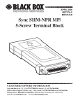
SHM-NPR and SHM-NPR/RJ
DCE
DTE
-NPR
SHM
DCE
DTE
-NPR
SHM
CUSTOMER
SUPPORT
INFORMATION
Order toll-free in the U.S. 24 hours, 7 A.M. Monday to midnight Friday: 877-877-BBOX
FREE technical support, 24 hours a day, 7 days a week: Call 724-746-5500 or fax 724-746-0746
Mail order: Black Box Corporation, 1000 Park Drive, Lawrence, PA 15055-1018
Web site: www.blackbox.com • E-mail: [email protected]
FCC/IC STATEMENTS
FEDERAL COMMUNICATIONS COMMISSION
AND
INDUSTRY CANADA
RADIO-FREQUENCY INTERFERENCE STATEMENTS
This equipment generates, uses, and can radiate radio frequency energy and if not
installed and used properly, that is, in strict accordance with the manufacturer’s
instructions, may cause interference to radio communication. It has been tested
and found to comply with the limits for a Class A computing device in accordance
with the specifications in Subpart J of Part 15 of FCC rules, which are designed to
provide reasonable protection against such interference when the equipment is
operated in a commercial environment. Operation of this equipment in a
residential area is likely to cause interference, in which case the user at his own
expense will be required to take whatever measures may be necessary to correct
the interference.
Changes or modifications not expressly approved by the party responsible for
compliance could void the user’s authority to operate the equipment.
If this equipment is attached to a device which requires the use of shielded cables
for compliance with FCC Part 15, then use of a filtered-pin connector might be
required to maintain FCC compliance.
This digital apparatus does not exceed the Class A limits for radio noise emission from
digital apparatus set out in the Radio Interference Regulation of Industry Canada.
Le présent appareil numérique n’émet pas de bruits radioélectriques dépassant les limites
applicables aux appareils numériques de classe A prescrites dans le Règlement sur le
brouillage radioélectrique publié par Industrie Canada.
1
SHM-NPR
NORMAS OFICIALES MEXICANAS (NOM)
ELECTRICAL SAFETY STATEMENT
INSTRUCCIONES DE SEGURIDAD
1. Todas las instrucciones de seguridad y operación deberán ser leídas antes
de que el aparato eléctrico sea operado.
2. Las instrucciones de seguridad y operación deberán ser guardadas para
referencia futura.
3. Todas las advertencias en el aparato eléctrico y en sus instrucciones
de operación deben ser respetadas.
4. Todas las instrucciones de operación y uso deben ser seguidas.
5. El aparato eléctrico no deberá ser usado cerca del agua—por ejemplo, cerca
de la tina de baño, lavabo, sótano mojado o cerca de una alberca, etc.
6. El aparato eléctrico debe ser usado únicamente con carritos o pedestales
que sean recomendados por el fabricante.
7. El parato eléctrico debe ser montado a la pared o al techo sólo como sea
recomendado por el fabricante.
8. Servicio—El usuario no debe intentar dar servicio al equipo eléctrico más allá
a lo descrito en las instrucciones de operación. Todo otro servicio deberá ser
referido a personal de servicio calificado.
9. El aparato eléctrico debe ser situado de tal manera que su posición no
interfiera su uso. La colocación del aparato eléctrico sobre una cama, sofá,
alfombra o superficie similar puede bloquea la ventilación, no se debe
colocar en libreros o gabinetes que impidan el flujo de aire por los orificios
de ventilación.
2
NOM STATEMENT
10. El equipo eléctrico deber ser situado fuera del alcance de fuentes de calor
como radiadores, registros de calor, estufas u otros aparatos (incluyendo
amplificadores) que producen calor.
11. El aparato eléctrico deberá ser connectado a una fuente de poder sólo del
tipo descrito en el instructivo de operación, o como se indique en el aparato.
12. Precaución debe ser tomada de tal manera que la tierra fisica y la polarización
del equipo no sea eliminada.
13. Los cables de la fuente de poder deben ser guiados de tal manera que
no sean pisados ni pellizcados por objetos colocados sobre o contra ellos,
poniendo particular atención a los contactos y receptáculos donde salen
del aparato.
14. El equipo eléctrico debe ser limpiado únicamente de acuerdo a las
recomendaciones del fabricante.
15. En caso de existir, una antena externa deberá ser localizada lejos de las lineas
de energia.
16. El cable de corriente deberá ser desconectado del cuando el equipo no sea
usado por un largo periodo de tiempo.
17. Cuidado debe ser tomado de tal manera que objectos liquidos no sean
derramados sobre la cubierta u orificios de ventilación.
18. Servicio por personal calificado deberá ser provisto cuando:
A: El cable de poder o el contacto ha sido dañado; u
B: Objectos han caído o líquido ha sido derramado dentro del aparato; o
C: El aparato ha sido expuesto a la lluvia; o
D: El aparato parece no operar normalmente o muestra un cambio
en su desempeño; o
E: El aparato ha sido tirado o su cubierta ha sido dañada.
3
SHM-NPR
Contents
Chapter
Page
1.
Specifications ............................................................................................. 5
2.
Introduction ............................................................................................... 7
3.
Configuration and Installation ................................................................. 9
3.1 Setting DTE or DCE ........................................................................... 9
3.2 The Installation Procedure ................................................................ 9
4.
Troubleshooting ......................................................................................
4.1 If You Have Difficulty ........................................................................
4.2 Calling Black Box ..............................................................................
4.3 Shipping and Packaging ...................................................................
12
12
12
13
Appendix A: RS-232 Pinout ............................................................................ 14
Appendix B: Maximum Distances ................................................................. 15
4
CHAPTER 1: Specifications
1. Specifications
Cable Required — 4-wire unloaded twisted pair with DC continuity
(not included)
Compliance —
FCC Class A, IC Class/classe A
Interfaces —
Device side: Serial EIA RS-232-C, DTE or DCE
(user-selectable, default DCE);
Line side: Proprietary balanced 4-wire
Protocol —
Asynchronous
Data Format —
Transparent to data format
Flow Control —
Does not support hardware flow control
(uses RS-232 control leads as power sources);
transparent to software flow control
Operation —
4-wire full duplex
Data Rate —
Up to 19,200 bps
Maximum
Distance—
Up to 17 mi. (27.3 km) depending on cable gauge
and data rate; see Appendix B
User Controls —
(1) Top-mounted DCE/DTE slide switch
Indicators —
None
Connectors —
ME721A-M, ME821A-M models: (1) Front-mounted
DB25 male;
ME721A-F, ME821A-F models: (1) Front-mounted DB25
female;
ME721 models: (1) Internal 5-screw terminal block with
strain relief;
ME821 models: (1) Rear-mounted RJ-12 (“6-wire RJ-11”)
female
5
SHM-NPR
Leads Supported — DB25 (RS-232): See Appendix A
Temperature
Tolerance—
32 to 112˚F (0 to 50˚C)
Humidity
Tolerance—
Up to 95% noncondensing
Enclosure —
High-impact plastic
Power —
±12 VDC, 6.3 mA from RS-232 interface:
From Pins 2, 4, 9, and/or 20 if the attached device
is DTE;
From Pins 3, 5, 6, 8, and/or 9 if the attached device
is DCE
CAUTION!
When the device to which a SHM-NPR is attached is
powered down, that SHM-NPR also loses power and
can no longer send any signals to the remote SHMNPR. In this condition, the idled cable between the
units becomes susceptible to receiving noise. If it
does, and the device to which the remote SHM-NPR
is attached is still powered ON, the remote SHMNPR might output spurious (“garbage”) data.
Size —
0.8"H x 1.8"W x 2.2"D (1.9 x 4.4 x 5.6 cm)
Weight —
2 oz. (57 g)
6
CHAPTER 2: Introduction
2. Introduction
Built using the latest surface-mount technology, the SHM-NPR and SHM-NPR/RJ
nonpowered short-haul modems attain high-quality performance in a low-profile
package. The units operate full-duplex at data rates up to 19.2 Kbps over two
twisted pairs (four wires). They require no AC power or batteries, but can support
distances up to 17 miles (27.3 km; see Appendix B).
The SHM-NPR and SHM-NPR/RJ have an external DCE/DTE switch, so you can
connect them to any type of RS-232 device without opening their chassis. And you
can terminate the line between pairs of these units in either of two ways: The SHMNPR models have a five-screw terminal block for hard-wired lines, and the SHMNPR/RJ models have modular RJ-12 (“6-wire RJ-11”) jacks. The specially designed
strain relief on the ME721 models prevents thin twisted pairs from breaking or
pulling loose.
RS-232 device-side
interface (DB25 male
on ME721A-M units,
DB25 female on
ME721A-F units)
DCE/DTE switch
DCE
DTE
Balanced line-side
interface (five-position
terminal block)
Figure 2-1. The SHM-NPR illustrated.
7
SHM-NPR
Typical applications for these units are shown—not to scale, obviously—in
Figures 2-2 and 2-3. In Figure 2-2, short-haul modems are being used to connect
an async host computer to a faraway terminal. (The thing to remember about such
applications is that if the computer and terminal are too widely separated, the host
will time out before receiving it receives the terminal’s responses.) In Figure 2-3,
short-haul modems are being used to enable a PC or server to send print jobs to
a distant serial printer.
Figure 2-2. Host-to-terminal application.
Figure 2-3. PC-to-serial-printer application.
8
CHAPTER 3: Configuration and Installation
3. Configuration and Installation
3.1 Setting DTE or DCE
You can configure your SHM-NPR or SHM-NPR/RJ as either a DTE or DCE device.
Just slide the DCE/DTE switch on the top of the unit (shown in Figure 3-1) to
“DCE” (if you are connecting the unit to a DTE such as a PC, terminal, serial
printer, etc.) or “DTE” (if you are connecting the unit to a DCE such as a modem).
You don’t need to open the unit’s cover to do this.
DCE
DTE
Figure 3-1. The DCE/DTE switch.
3.2 The Installation Procedure
On its device side, your SHM-NPR or SHM-NPR/RJ is designed to be plugged
directly into one of the RS-232 serial ports on a terminal, computer, serial printer,
modem, etc. For most applications, this eliminates the need for an RS-232-C data
cable. (If you do need to use one for whatever reason, we recommend a shielded
cable—our EDN25C, for example—that carries all of the pins from which the
SHM-NPR draws power; just make sure to keep this cable as short as possible.) No
power is required from a dedicated AC or DC source, because the unit is powered
entirely by the attached device’s control and data signals.
On its line side, your SHM-NPR or SHM-NPR/RJ has a proprietary balanced
4-wire twisted-pair communication-line interface.
9
SHM-NPR
To install a pair of these units, take these steps:
1A. SHM-NPR (ME721 models) only: Making sure that they are not connected to
any other device or any power source, gently pry the units open using a small
screwdriver or similar tool wedged into one of the indentations on either side
of the units’ cases. This will reveal a 5-screw terminal block mounted inside
each unit. Run 4-wire twisted-pair cable (not included) from one block to the
other as shown in Figure 3-2: one pair TX A to RX A and TX B to RX B, the
other pair RX A to TX A and RX B to TX B, and the shield (if the cable is
shielded) to the ground (middle) screw on one end of the cable only. When you
are finished, lay the cable in the semicircle where it will emerge from the unit
so that the strain-relief prongs can pierce the cable jacket, then close the unit
back up.
CAUTION!
Under no circumstances should you attach the cable shield to the
ground screws on both ends; this could cause damaging electrical
“ground loops.”
Neither should you ever connect these units to the public switched
telephone system in any way. This could also severely damage your
equipment.
XMTXMT+
G
RCV+
RCV-
RCVRCV+
G
XMT+
XMT-
Figure 3-2. Wiring a pair of ME721 units.
10
CHAPTER 3: Configuration and Installation
1B. SHM-NPR/RJ (ME821 models) only: Get 4-wire twisted-pair cable and terminate
it with RJ-11 or (especially if the cable is shielded) RJ-12 plugs, using the pin
assignments shown in Figure 3-3 (for RJ-11 cable, substitute Pins 1, 2, 3, and
4 for Pins 2, 3, 4, and 5 respectively) and end-to-end wiring like that shown
in Figure 3-2 on the previous page. Also, if the cable is shielded, attach the
shield to Pin 1 or 6 on one end of the cable only. Plug the cable into the RJ-12
jacks on the units.
CAUTION!
Under no circumstances should you attach the cable shield to Pin 1 or 6
on both ends; this could cause damaging electrical “ground loops.”
Neither should you ever connect these units to the public switched
telephone system in any way. This could also severely damage your
equipment.
FEMALE
PINS
123456
Unit—Pins 1
and 6 connected
to frame ground
MALE
2 (RCV-)
3 (XMT+)
4 (XMT-)
5 (RCV+)
Cable—Pin 1 or 6
connected to shield
on one end only;
for end-to-end
pinning, refer to
Figure 3-2 on the
previous page
Figure 3-3. Wiring a cable for ME821 units.
2. Both models: Plug the units’ DB25 connectors into the RS-232 serial ports
on the corresponding devices and tighten the mounting screws.
That’s all there is to it. Assuming your units’ DCE/DTE switches are set properly,
your SHM-NPR or SHM-NPR/RJ system should be ready for continuous operation.
11
SHM-NPR
4. Troubleshooting
4.1 If You Have Difficulty
If your SHM-NPR or SHM-NPR/RJ system does not seem to be operating properly,
here are a few things to check first:
1. Is the DCE/DTE switch set correctly on each of the short-haul modems? If the
attached device is a DTE (computer, PC, terminal, printer, etc.), this switch
should be set to DCE; if the attached device is a DCE (modem, etc.), this
switch should be set to DTE. See also Section 3.1.
2. Check all external connections. Make sure they are firm and secure.
3. SHM-NPR (ME721) only: Detach the unit from the device and open its case.
Make sure that none of the wires have come loose from the terminal block.
4. Use a cable tester to test the cable for continuity and pinning.
If you still can’t determine what is causing the problem, call Black Box
Technical Support as described in the next section.
4.2 Calling Black Box
If you determine that your SHM-NPR or SHM-NPR/RJ is malfunctioning, do not
attempt to alter or repair the unit. It contains no user-serviceable parts. Contact Black
Box Technical Support at 724-746-5500.
Before you do, make a record of the history of the problem. We will be able to
provide more efficient and accurate assistance if you have a complete description,
including:
• the nature and duration of the problem.
• when the problem occurs.
• the components involved in the problem.
• any particular application that, when used,
appears to create the problem or make it worse.
• the results of any testing you’ve already done.
12
CHAPTER 4: Troubleshooting
4.3 Shipping and Packaging
If you need to transport or ship your SHM-NPR or SHM-NPR/RJ:
• Package it carefully. We recommend that you use the original container.
• If you are returning the unit, make sure you include everything your received
with it. Before you ship the unit back to us for whatever reason, contact Black
Box to get a Return Materials Authorization (RMA) number.
13
SHM-NPR
Appendix A: RS-232 Pinout
The table below shows how the RS-232-C ports of the SHM-NPR and SHM-NPR/RJ
are pinned out. Please note that even though the control and voltage signals are
listed, they are used only to help power the units; only the data signals are carried
across the line.
PIN
1
2
3
4
5
6
7
8
9
20
CIRC.
AA
BA
BB
CA
CB
CC
AB
CF
—
CD
DESCRIPTION
Protective Ground
Transmitted Data
Receive Data
Request to Send
Clear to Send
Data Set Ready
Signal Ground
Data Carrier Detect
+12 VDC
Data Terminal Ready
FUNCTION
Ground
Data
Data
Control
Control
Control
Ground
Control
Voltage
Control
DIRECTION
N/A
To DCE
From DCE
To DCE
From DCE
From DCE
N/A
From DCE
From attached device
To DCE
Note: Pins 1 & 7 are tied together inside the unit, as are Pins 4 & 5 and Pins 6, 8, & 20.
14
APPENDIX B: Maximum Distances
Appendix B: Maximum Distances
The table below shows how far pairs of SHM-NPRs and SHM-NPR/RJs can transmit
data to each other at specified cable thicknesses and data rates. Please note that
these measurements are for noiseless environments with not more than 20%
of peak-to-peak distortion; figures for lines run through electrically noisy
environments—near fluorescent lighting, elevators, generators, compressors,
or motors, for example—will be dramatically lower.
Data
Rate
(bps)
Maximum Distance in Miles (km) for:
Cable Gauge [AWG] (diameter):
19 (0.9 mm)
24 (0.5 mm)
26 (0.4 mm)
19,200
6.2 (9.9)
3.7 (5.9)
1.2 (1.9)
9,600
7.5 (12.0)
4.9 (7.8)
2.5 (4.0)
4,800
8.7 (13.9)
5.6 (9.0)
3.7 (5.9)
2,400
11.8 (18.9)
8.0 (12.8)
4.9 (7.8)
1,200
17.0 (27.2)
11.8 (18.9)
8.0 (12.8)
15
©Copyright 2000. Black Box Corporation. All rights reserved.
1000 Park Drive • Lawrence, PA 15055-1018 • 724-746-5500 • Fax 724-746-0746


