1
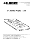
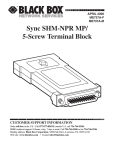
JANUARY 2001
LRA1215A
T1 Provider Backhaul Unit, 1-Port
t
der
rovi -Por
T1 Pl Unit 1
au
ckh
Ba
Lnk
tion
Act onnec
tC
rne
100 Ethe
t
Fas
er
Pow
Alm
tion
Lnk onnec
T1 C
CUSTOMER
SUPPORT
INFORMATION
Order toll-free in the U.S.: Call 877-877-BBOX (outside U.S. call 724-746-5500)
FREE technical support 24 hours a day, 7 days a week: Call 724-746-5500 or fax 724-746-0746
Mailing address: Black Box Corporation, 1000 Park Drive, Lawrence, PA 15055-1018
Web site: www.blackbox.com • E-mail: [email protected]
FCC INFORMATION
FEDERAL COMMUNICATIONS COMMISSION
AND
INDUSTRY CANADA
RADIO FREQUENCY INTERFERENCE STATEMENTS
This equipment generates, uses, and can radiate radio frequency energy and if not
installed and used properly, that is, in strict accordance with the manufacturer’s
instructions, may cause interference to radio communication. It has been tested
and found to comply with the limits for a Class A computing device in accordance
with the specifications in Subpart J of Part 15 of FCC rules, which are designed to
provide reasonable protection against such interference when the equipment is
operated in a commercial environment. Operation of this equipment in a
residential area is likely to cause interference, in which case the user at his own
expense will be required to take whatever measures may be necessary to correct
the interference.
Changes or modifications not expressly approved by the party responsible
for compliance could void the user’s authority to operate the equipment.
This digital apparatus does not exceed the Class A limits for radio noise emission from
digital apparatus set out in the Radio Interference Regulation of Industry Canada.
Le présent appareil numérique n’émet pas de bruits radioélectriques dépassant les limites
applicables aux appareils numériques de la classe A prescrites dans le Règlement sur le
brouillage radioélectrique publié par Industrie Canada.
1
T1 PROVIDER BACKHAUL UNIT, 1-PORT
NORMAS OFICIALES MEXICANAS (NOM)
ELECTRICAL SAFETY STATEMENT
INSTRUCCIONES DE SEGURIDAD
1. Todas las instrucciones de seguridad y operación deberán ser leídas antes de
que el aparato eléctrico sea operado.
2. Las instrucciones de seguridad y operación deberán ser guardadas para
referencia futura.
3. Todas las advertencias en el aparato eléctrico y en sus instrucciones de
operación deben ser respetadas.
4. Todas las instrucciones de operación y uso deben ser seguidas.
5. El aparato eléctrico no deberá ser usado cerca del agua—por ejemplo, cerca
de la tina de baño, lavabo, sótano mojado o cerca de una alberca, etc..
6. El aparato eléctrico debe ser usado únicamente con carritos o pedestales que
sean recomendados por el fabricante.
7. El aparato eléctrico debe ser montado a la pared o al techo sólo como sea
recomendado por el fabricante.
8. Servicio—El usuario no debe intentar dar servicio al equipo eléctrico más allá
a lo descrito en las instrucciones de operación. Todo otro servicio deberá ser
referido a personal de servicio calificado.
9. El aparato eléctrico debe ser situado de tal manera que su posición no
interfiera su uso. La colocación del aparato eléctrico sobre una cama, sofá,
alfombra o superficie similar puede bloquea la ventilación, no se debe colocar
en libreros o gabinetes que impidan el flujo de aire por los orificios de
ventilación.
10. El equipo eléctrico deber ser situado fuera del alcance de fuentes de calor
como radiadores, registros de calor, estufas u otros aparatos (incluyendo
amplificadores) que producen calor.
11. El aparato eléctrico deberá ser connectado a una fuente de poder sólo del
tipo descrito en el instructivo de operación, o como se indique en el aparato.
2
NOM STATEMENT
12. Precaución debe ser tomada de tal manera que la tierra fisica y la polarización
del equipo no sea eliminada.
13. Los cables de la fuente de poder deben ser guiados de tal manera que no
sean pisados ni pellizcados por objetos colocados sobre o contra ellos,
poniendo particular atención a los contactos y receptáculos donde salen del
aparato.
14. El equipo eléctrico debe ser limpiado únicamente de acuerdo a las
recomendaciones del fabricante.
15. En caso de existir, una antena externa deberá ser localizada lejos de las lineas
de energia.
16. El cable de corriente deberá ser desconectado del cuando el equipo no sea
usado por un largo periodo de tiempo.
17. Cuidado debe ser tomado de tal manera que objectos liquidos no sean
derramados sobre la cubierta u orificios de ventilación.
18. Servicio por personal calificado deberá ser provisto cuando:
A: El cable de poder o el contacto ha sido dañado; u
B: Objectos han caído o líquido ha sido derramado dentro del aparato; o
C: El aparato ha sido expuesto a la lluvia; o
D: El aparato parece no operar normalmente o muestra un cambio en su
desempeño; o
E: El aparato ha sido tirado o su cubierta ha sido dañada.
3
T1 PROVIDER BACKHAUL UNIT, 1-PORT
TRADEMARKS USED IN THIS MANUAL
Any trademarks mentioned in this manual are acknowledged to be the property of the
trademark owners.
4
CHAPTER 1: Introduction
1. Introduction
These instructions provide basic installation procedures for the T1 Provider
Backhaul Unit, 1-Port (LRA1215A).
CAUTION
Excess static electricity can damage your unit. Use proper staticprotection handling techniques when installing and handling this
equipment.
5
T1 PROVIDER BACKHAUL UNIT, 1-PORT
2. Installation
1. Unpack the T1 Provider Backhaul Unit, 1-Port and power supply.
2. Plug the power supply into both the power source and the back of the unit. It
does not matter which order. Verify that the Power LED is lit.
NOTE
The unit’s 100 LED, Act LED, and Lnk LEDs will also light until the T1
link has been established. In addition, the unit won’t present Ethernet
Link when the T1 line is not operational.
3. Verify switch configuration is correct for the T1 line (see Table 2-1).
Table 2-1. T1 Provider Backhaul Unit 1-Port Switch Configuration
Switch #1
Switch #2
DOWN
UP
DOWN
UP
*Default settings.
DOWN
DOWN
UP
UP
Timeslots
1-24
1–18
1–12
1–6
Bandwidth
1.536 Mbps*
1.152 Mbps
768 kbps
384 kbps
Switch #3: ESF (DOWN) or SF [D4] (UP)
Switch #4: B8ZS (DOWN) or AMI (UP)
Switch #5 LBO Low
Switch #6 LBO High
UP
DOWN
UP
DOWN
UP
UP
DOWN
DOWN
Switch #7: Local (DOWN) or Loop (UP) Timing
Switch #8: Not used
6
Line Attenuation
-22.5 dB
-15 dB
-7.5 dB
0 dB
CHAPTER 2: Installation
4. Plug in the T1 connection.
Table 2-2. T1 Pinout Information
Pin Number
Signal
1
2
3
4
5
6
7
8
RX Ring
RX Tip
Shield Ground*
TX Ring
TX Tip
Shield Ground*
Shield Ground*
Shield Ground*
*Only required when using shielded T1 cable.
5. Verify the T1 connection via the T1 Link LED on the front of the unit. A
steadily pulsing T1 Lnk LED (once per second) indicates that a T1
connection is established and operational.
6. Plug in the local Ethernet connection and verify physical link by the Lnk LED
on the front of the unit. See Table 2-3.
Table 2-3. Ethernet Pinout
Pin Number
Signal
1
2
3
4
5
6
7
8
RX+
RXTX+
Not used
Not used
TXNot used
Not used
NOTE
For most applications, use a straight-through Ethernet cable when
plugging the Provider Unit into a PC. Use a cross-over cable when
plugging into a hub or a switch. Verify the pinout of the Ethernet device
into which you are connecting the Provider Unit to determine which type
of cable is required.
7
T1 PROVIDER BACKHAUL UNIT, 1-PORT
Once the units have established both T1 and Ethernet links on both sides of the
connection, normal data communication will flow through the units. This will
provide a very long Ethernet connection at T1 or fractional T1 speeds.
LED Indicators (also described on bottom label)
• T1 Lnk LED: Flashing green indicates that the T1 is operational (no Red
Alarm).
• T1 Alm LED: Steady/flashing amber indicates a Yellow/Blue Alarm.
• Power LED: Steady green indicates normal operation.
• 100 LED: Steady green indicates a Fast Ethernet (100-Mbps) connection.
• Act LED: Flashing amber indicates activity on the Ethernet segment.
• Lnk LED: Steady green indicates that an Ethernet link has been established.
8
© Copyright 2001. Black Box Corporation. All rights reserved.
1000 Park Drive • Lawrence, PA 15055-1018 • 724-746-5500 • Fax 724-746-0746