1
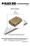
MARCH 2001
LRA1209C
E1 12-Port Access Multiplexor Module
E1
s
Acces or
ex
Multipl
PWR
AL LK
RX TX
1
2
3
4
5
E
1
6
7
8
9
10
11
12
CUSTOMER
SUPPORT
INFORMATION
Order toll-free in the U.S.: Call 877-877-BBOX (outside U.S. call 724-746-5500)
FREE technical support 24 hours a day, 7 days a week: Call 724-746-5500 or fax 724-746-0746
Mailing address: Black Box Corporation, 1000 Park Drive, Lawrence, PA 15055-1018
Web site: www.blackbox.com • E-mail: [email protected]
FCC INFORMATION
FEDERAL COMMUNICATIONS COMMISSION
AND
INDUSTRY CANADA
RADIO FREQUENCY INTERFERENCE STATEMENTS
This equipment generates, uses, and can radiate radio frequency energy and if not
installed and used properly, that is, in strict accordance with the manufacturer’s
instructions, may cause interference to radio communication. It has been tested
and found to comply with the limits for a Class A computing device in accordance
with the specifications in Subpart J of Part 15 of FCC rules, which are designed to
provide reasonable protection against such interference when the equipment is
operated in a commercial environment. Operation of this equipment in a
residential area is likely to cause interference, in which case the user at his own
expense will be required to take whatever measures may be necessary to correct
the interference.
Changes or modifications not expressly approved by the party responsible
for compliance could void the user’s authority to operate the equipment.
This digital apparatus does not exceed the Class A limits for radio noise emission from
digital apparatus set out in the Radio Interference Regulation of Industry Canada.
Le présent appareil numérique n’émet pas de bruits radioélectriques dépassant les limites
applicables aux appareils numériques de la classe A prescrites dans le Règlement sur le
brouillage radioélectrique publié par Industrie Canada.
1
E1 12-PORT ACCESS MULTIPLEXOR MODULE
NORMAS OFICIALES MEXICANAS (NOM)
ELECTRICAL SAFETY STATEMENT
INSTRUCCIONES DE SEGURIDAD
1. Todas las instrucciones de seguridad y operación deberán ser leídas antes de
que el aparato eléctrico sea operado.
2. Las instrucciones de seguridad y operación deberán ser guardadas para
referencia futura.
3. Todas las advertencias en el aparato eléctrico y en sus instrucciones de
operación deben ser respetadas.
4. Todas las instrucciones de operación y uso deben ser seguidas.
5. El aparato eléctrico no deberá ser usado cerca del agua—por ejemplo, cerca
de la tina de baño, lavabo, sótano mojado o cerca de una alberca, etc..
6. El aparato eléctrico debe ser usado únicamente con carritos o pedestales que
sean recomendados por el fabricante.
7. El aparato eléctrico debe ser montado a la pared o al techo sólo como sea
recomendado por el fabricante.
8. Servicio—El usuario no debe intentar dar servicio al equipo eléctrico más allá
a lo descrito en las instrucciones de operación. Todo otro servicio deberá ser
referido a personal de servicio calificado.
9. El aparato eléctrico debe ser situado de tal manera que su posición no
interfiera su uso. La colocación del aparato eléctrico sobre una cama, sofá,
alfombra o superficie similar puede bloquea la ventilación, no se debe colocar
en libreros o gabinetes que impidan el flujo de aire por los orificios de
ventilación.
10. El equipo eléctrico deber ser situado fuera del alcance de fuentes de calor
como radiadores, registros de calor, estufas u otros aparatos (incluyendo
amplificadores) que producen calor.
11. El aparato eléctrico deberá ser connectado a una fuente de poder sólo del
tipo descrito en el instructivo de operación, o como se indique en el aparato.
2
NOM STATEMENT
12. Precaución debe ser tomada de tal manera que la tierra fisica y la polarización
del equipo no sea eliminada.
13. Los cables de la fuente de poder deben ser guiados de tal manera que no
sean pisados ni pellizcados por objetos colocados sobre o contra ellos,
poniendo particular atención a los contactos y receptáculos donde salen del
aparato.
14. El equipo eléctrico debe ser limpiado únicamente de acuerdo a las
recomendaciones del fabricante.
15. En caso de existir, una antena externa deberá ser localizada lejos de las lineas
de energia.
16. El cable de corriente deberá ser desconectado del cuando el equipo no sea
usado por un largo periodo de tiempo.
17. Cuidado debe ser tomado de tal manera que objectos liquidos no sean
derramados sobre la cubierta u orificios de ventilación.
18. Servicio por personal calificado deberá ser provisto cuando:
A: El cable de poder o el contacto ha sido dañado; u
B: Objectos han caído o líquido ha sido derramado dentro del aparato; o
C: El aparato ha sido expuesto a la lluvia; o
D: El aparato parece no operar normalmente o muestra un cambio en su
desempeño; o
E: El aparato ha sido tirado o su cubierta ha sido dañada.
3
E1 12-PORT ACCESS MULTIPLEXOR MODULE
TRADEMARKS USED IN THIS MANUAL
Any trademarks mentioned in this manual are acknowledged to be the property of the
trademark owners.
4
CHAPTER 1: Introduction
1. Introduction
The E1 12-Port Access Multiplexor Module is a 12-port module for use with the 2 x
12 or 1 x 4 slot DSLAM Chassis. The module attaches to each Multiplexor Uplink
Module (MUM) via a 10-/100-Mbps Ethernet connection on the backplane. Each
E1 port translates the outgoing Ethernet frame to E1 via media conversion. This is
a Layer-1 conversion, where the native frames are then passed across the E1 link,
over a copper pair to an E1 Subscriber Unit. Received WAN frames are converted
back to Ethernet and forwarded to the appropriate backplane port. No routing or
translational bridging is done internally.
The connection across the E1 line may be a fractional or full E1. Speed is
hardware- or software-selectable per port (software overrides hardware settings)
and determined by the E1 12-Port Access Multiplexor Module. Eight speed
(bandwidth) settings are possible: 256, 512, 768, 1024, 1280, 1536, 1792, and 1984
kbps. The remote Subscriber Unit will determine its line speed through
communication with the 12-Port Module. E1 technology is intended for use from
the telephone company central office across the local loop to the home or
business, or may also be used to transport data between locations over E1 lines.
5
E1 12-PORT ACCESS MULTIPLEXOR MODULE
2. Installation
2.1 Bandwidth Selection
The E1 12-Port Access Multiplexor Module provides 8 bandwidth options for the
E1 link, as mentioned in Chapter 1. Two switch banks (12 switches per bank)
located on the circuit board are used to select the default bandwidth. The switches
affect the operation of the E1 connection only. These switches are paired in groups
of two, with each group affecting a single E1 port. Table 1 depicts switch/port
associations.
Table 1. Switch/port associations.
Upper Switch Bank Switches
2
6
12
20
30
42
Port 1
Port 2
Port 3
Port 4
Port 5
Port 6
Middle Switch Bank Switches
1–2
3–4
5–6
7–8
9–10
11–12
Port 7
Port 8
Port 9
Port 10
Port 11
Port 12
Table 2 shows the switch settings used to determine the default speed setting per
port. When operating a port as a Fractional E1 line, the equipment requires
contiguous timeslots, as indicated
Table 2. Default speed settings.
6
Switch One
Switch Two
ON
OFF
ON
OFF
ON
ON
OFF
OFF
Timeslots
1–31
1–24
1–16
1–8
Bandwidth
1.984 Mbps
1.536 Mbps
1.024 Mbps
512 kbps
CHAPTER 2: Installation
A third (lower) switch bank selects the following (see Table 3) for all of the E1
lines.
Table 3. E1 line settings.
Switch
ON
OFF
1 (Framing)
2 (Line Coding)
3 (Not Used)
4 (Not Used)
5 (Timing)
6 (Not Used)
E1 (CRC)
HDB3
E1 (no CRC)
AMI
Local
Loop
The E1 12-Port Access Multiplexor Module ships with all switches in the ON
position, meaning each port will run at 1.984 Mbps, E1 (CRC) Framing, HDB3
Line Coding, and Local Timing by default.
NOTE
Speed settings made via the Web Management System override the
hardware settings.
7
E1 12-PORT ACCESS MULTIPLEXOR MODULE
2.2 Port Pinout
Table 4 lists the pinout for the E1 RJ-21 connector.
Table 4. E1 RJ-21 connector pinout.
Port
1
2
3
4
5
6
7
8
9
10
11
12
8
Pin
26
1
27
2
28
3
29
4
30
5
31
6
32
7
33
8
34
9
35
10
36
11
37
12
Pin
RxT
RxR
RxT
RxR
RxT
RxR
RxT
RxR
RxT
RxR
RxT
RxR
RxT
RxR
RxT
RxR
RxT
RxR
RxT
RxR
RxT
RxR
RxT
RxR
39
14
40
15
41
16
42
17
43
18
44
19
45
20
46
21
47
22
48
23
49
24
50
25
TxT
TxR
TxT
TxR
TxT
TxR
TxT
TxR
TxT
TxR
TxT
TxR
TxT
TxR
TxT
TxR
TxT
TxR
TxT
TxR
TxT
TxR
TxT
TxR
CHAPTER 2: Installation
2.3 LED Indicators
Each E1 port features these status LEDs for at-a-glance monitoring:
• PWR: Steady green indicates normal operation.
• LK: Pulsing green (once per second) indicates E1 connection is operational
and the unit is receiving either valid data packets or status packets from the
remote unit on the other side of the E1 connection.
Solid green indicates link (frame synchronization), but no traffic is being
received.
No green indicates red alarm (carrier failure alarm).
• RX: Flashing amber indicates data received from the E1 line.
• TX: Flashing amber indicates data transmit to the T1 line.
• AL: Solid amber indicates AIS (alarm indication signal).
9
© Copyright 2001. Black Box Corporation. All rights reserved.
1000 Park Drive • Lawrence, PA 15055-1018 • 724-746-5500 • Fax 724-746-0746