1
ME310A
ME310AE
ME315A
JULY 1997
ME315AE
ME320A
ME320AE
S
W
1
J1
l
ia
tr
us er
d
r
In Fibve
ri
D
34
12 W2
S
7
56
8
J4
J3
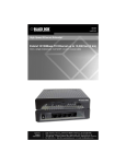
Industrial Fiber Drivers
CUSTOMER SUPPORT INFORMATION
Order toll-free in the U.S. 24 hours, 7 A.M. Monday to midnight Friday: 877-877-BBOX
FREE technical support, 24 hours a day, 7 days a week: Call 724-746-5500 or fax 724-746-0746
Mail order: Black Box Corporation, 1000 Park Drive, Lawrence, PA 15055-1018
Web site: www.blackbox.com • E-mail: [email protected]
FCC AND IC STATEMENTS
FEDERAL COMMUNICATIONS COMMISSION
AND
INDUSTRY CANADA
RADIO FREQUENCY INTERFERENCE STATEMENTS
This equipment generates, uses, and can radiate radio frequency energy
and if not installed and used properly, that is, in strict accordance with
the manufacturer’s instructions, may cause interference to radio
communication. It has been tested and found to comply with the limits
for a Class A computing device in accordance with the specifications in
Subpart J of Part 15 of FCC rules, which are designed to provide reasonable
protection against such interference when the equipment is operated in
a commercial environment. Operation of this equipment in a residential
area is likely to cause interference, in which case the user at his own
expense will be required to take whatever measures may be necessary
to correct the interference.
Changes or modifications not expressly approved by the party responsible
for compliance could void the user’s authority to operate the equipment.
This digital apparatus does not exceed the Class A limits for radio noise emission
from digital apparatus set out in the Radio Interference Regulation of Industry
Canada.
Le présent appareil numérique n’émet pas de bruits radioélectriques dépassant les
limites applicables aux appareils numériques de classe A prescrites dans le Règlement
sur le brouillage radioélectrique publié par Industrie Canada.
1
INDUSTRIAL FIBER DRIVERS
NORMAS OFICIALES MEXICANAS (NOM)
ELECTRICAL SAFETY STATEMENT
INSTRUCCIONES DE SEGURIDAD
1. Todas las instrucciones de seguridad y operación deberán ser leídas
antes de que el aparato eléctrico sea operado.
2. Las instrucciones de seguridad y operación deberán ser guardadas
para referencia futura.
3. Todas las advertencias en el aparato eléctrico y en sus instrucciones
de operación deben ser respetadas.
4. Todas las instrucciones de operación y uso deben ser seguidas.
5. El aparato eléctrico no deberá ser usado cerca del agua—por
ejemplo, cerca de la tina de baño, lavabo, sótano mojado o cerca de
una alberca, etc..
6. El aparato eléctrico debe ser usado únicamente con carritos o
pedestales que sean recomendados por el fabricante.
7. El aparato eléctrico debe ser montado a la pared o al techo sólo
como sea recomendado por el fabricante.
8. Servicio—El usuario no debe intentar dar servicio al equipo eléctrico
más allá a lo descrito en las instrucciones de operación. Todo otro
servicio deberá ser referido a personal de servicio calificado.
9. El aparato eléctrico debe ser situado de tal manera que su posición
no interfiera su uso. La colocación del aparato eléctrico sobre una
cama, sofá, alfombra o superficie similar puede bloquea la
ventilación, no se debe colocar en libreros o gabinetes que impidan
el flujo de aire por los orificios de ventilación.
10. El equipo eléctrico deber ser situado fuera del alcance de fuentes
de calor como radiadores, registros de calor, estufas u otros aparatos
(incluyendo amplificadores) que producen calor.
2
NOM STATEMENT
11. El aparato eléctrico deberá ser connectado a una fuente de poder
sólo del tipo descrito en el instructivo de operación, o como se
indique en el aparato.
12. Precaución debe ser tomada de tal manera que la tierra fisica y la
polarización del equipo no sea eliminada.
13. Los cables de la fuente de poder deben ser guiados de tal manera
que no sean pisados ni pellizcados por objetos colocados sobre o
contra ellos, poniendo particular atención a los contactos y
receptáculos donde salen del aparato.
14. El equipo eléctrico debe ser limpiado únicamente de acuerdo
a las recomendaciones del fabricante.
15. En caso de existir, una antena externa deberá ser localizada lejos
de las lineas de energia.
16. El cable de corriente deberá ser desconectado del cuando el equipo
no sea usado por un largo periodo de tiempo.
17. Cuidado debe ser tomado de tal manera que objectos liquidos
no sean derramados sobre la cubierta u orificios de ventilación.
18. Servicio por personal calificado deberá ser provisto cuando:
A:
El cable de poder o el contacto ha sido dañado; u
B:
Objectos han caído o líquido ha sido derramado dentro
del aparato; o
C:
El aparato ha sido expuesto a la lluvia; o
D:
El aparato parece no operar normalmente o muestra un cambio
en su desempeño; o
E:
El aparato ha sido tirado o su cubierta ha sido dañada.
3
INDUSTRIAL FIBER DRIVERS
Contents
Chapter
Page
1. Specifications ......................................................5
2. Introduction ......................................................10
3. Installation ........................................................11
3.1 Serial RS-232 Fiber Drivers ....................11
3.2 Serial RS-485 Fiber Drivers ....................16
3.3 Parallel Fiber Drivers..............................21
3.4 Mixed Operation ....................................26
3.4.1 Interconnection ..........................27
3.4.2 Differences Between Serial
RS-232 and Serial RS-485 ............29
4. Troubleshooting................................................30
4.1 Calling Black Box ..................................31
4.2 Shipping and Packaging ........................32
4
CHAPTER 1: Specifications
1. Specifications
Speed —
Serial: 115.2 Kbps;
Parallel: 230 Kbps
in nibble mode
Distance —
Varies with fiber type and dB
loss (fiber budget)
Data Format —
Serial Data: 7 data bits, even
or odd parity; 8 data bits, no
parity;
Parallel Data: 8 data
bits (host to peripheral)
Switches —
RS-232: (1) 8-position DIP
switch, (1) Slide DTE/DCE
switch;
RS-485: (1) 8-position
DIP switch, (1) Slide
Terminated/Unterminated
switch;
Parallel: (1) 4-position
DIP switch, (1) Slide
Input/Output switch
5
INDUSTRIAL FIBER DRIVERS
Connectors —
Fiber: (2) ST;
RS-232: DB25 female;
RS-485: DB9 male;
Parallel: DB25 female (PC
standard pinout)
Flow Control —
Serial to Serial will pass
X-ON/X-OFF or hardware;
parallel applications are
hardware only; RS-485
applications pass data only
Parallel
Interface —
Serial RS-232
Interface —
Serial RS-485
Interface —
6
IBM® PC parallel interface
compatible; operation
complies with IEEE Std. 12841994, supporting Compatibility
and Nibble Modes
EIA RS-232-C; CCITT V.24,
V.28; ISO 2110
2- or 4-wire (RS-422 or
RS-485)
CHAPTER 1: Specifications
Optical
Wavelength —
820 nm
Fiber Output
Power —
100 µW, or see Table 1-1
Fiber Input
Receiver
Sensitivity —
1µW or -30 dBm
Fiber
Compatibility —
Single-mode: 8/125 µ;
Multi-mode: 50-µ to 200-µ core
MTBF —
>75,000 hours
Operating
Temperature —
32 to 158°F (0 to 70°C)
Storage
Temperature —
14 to 185°F (-10 to +85°C)
Humidity
Tolerance —
10 to 95%, noncondensing
7
INDUSTRIAL FIBER DRIVERS
Maximum
Altitude
Tolerance —
15,000 feet (4570 m)
Power —
ME310A, ME315A, ME320A:
115 VAC, 12W (1.75W for
ME310A), Output of
9VDC, 500 mA; ME310AE,
ME315AE, ME320AE:
230 VAC, 12W, Output of
9VDC, 500 mA
Size —
1"H x 2.3"W x 3.7"D
(2.5 x 5.8 x 9.4 cm)
Weight —
1.4 lb. (0.6 kg)
with power supply
8
CHAPTER 1: Specifications
Table 1-1. Approximate Values into Multimode and Single-Mode
Fiber (calculated)
(In µW/dBm)
Output Power Maximum Medium
Minimum
Multimode
50µ core
62.5µ core
50/-13
110/-9.6
30/-15.2
66/-12
10/-20
22/-17
100µ core
290/-5.4
174/-8
58/-12.2
2.5/-26
1.7/-27.7
0.55/-33
Single mode
8/125µ
9
INDUSTRIAL FIBER DRIVERS
2. Introduction
Industrial Fiber Drivers extend your serial RS-232
(ME320 models), serial RS-485 (ME310 models),
or IBM® PC parallel (ME315 models) interfaces over
single or multimode fiber.
The Fiber Drivers are available in sets, or you can
order them separately to accommodate a mixed
application. You can start with RS-232, then transmit
over fiber to a parallel Fiber Driver at the remote
end.
The Fiber Driver’s input or output operation is
selectable to prevent the problem of having two
modules that are transmitting (input) devices
and no receiving (output) device.
The serial RS-232 modules are switch-selectable
for either DTE or DCE application, eliminating
the need for special cables.
ST® style connectors provide single-mode or
multimode (fiberoptic cable) compatibility and
ensure ease of installation in most applications
and environments.
10
CHAPTER 3: Installation
3. Installation
Before you begin, make sure all equipment is
off and the Fiber Drivers are not powered on.
3.1 Serial RS-232 Fiber Drivers
In a Serial-to-Serial application, use the charts in this
section to set switch setting (S2) for baud rate and
transmission length (optical power). Set S1 for either
DCE (to connect to a PC) or DTE (to connect to a
modem).
Attach the two devices with single-mode or multimode fiberoptic cable with ST style connectors.
Make sure to connect the transmitter output of
each unit to the receiver input of the other unit.
Once all connections are made, connect DB25 cables
to the equipment and power up the Fiber Drivers.
Now you can apply power to your equipment.
For testing purposes, a self-test has been
incorporated into the Fiber Driver. To enable
the test, S2-4 needs to be placed in the up (open)
position. The self-test will be transmitted to the
serial port. If a PC is the receiving device, a terminalemulation program will need to be running.
11
INDUSTRIAL FIBER DRIVERS
S1
B
A
C1
C2
C3
C4
S2
Figure 3-1. Serial RS-232 Fiber Driver
Switch and Connector Layout.
Connectors
C1 — DC Power Jack (9 VDC @ 500 mA)
C2 — DB25 Female RS-232
C3 — (Receiver Input) ST style fiberoptic connector
C4 — (Transmitter Output) ST style fiberoptic
connector
12
CHAPTER 3: Installation
Table 3-1. Connector C2 pinout
Pin - Signal
DCE
Interface
Function
(S1-A)
2 - Transmitted Data
3 - Received Data
4 - Request To Send
Input
Output
Connected
to pin 5
Connected
to pin 4
Output
Ground
Open
7 to 12 VDC
@ 250 mA
Input
Open
5 - Clear To Send
6 - Data Set Ready
7 - Common
8 - Data Carrier Detect
9 - + (optional)
20 - Data Terminal Ready
22 - Ring Indicator
DTE
Interface
Function
(S1-B)
Output
Input
Connected to pin 5
Connected to pin 4
Input
Ground
Open
7 to 12 VDC
@ 250 mA
Output
Open
DCE — Data Carrier Equipment
(can connect to a PC)
DTE — Data Terminal Equipment
(configured the same as a PC)
NOTE:The Fiber Driver may be powered with either power jack
(connector C1 or pin 9 of the DB25 female, C2).
13
INDUSTRIAL FIBER DRIVERS
Switches
S1 — (Receiver Input) 2-Position Slide switch
S2 — 8-Position DIP switch (Up is open, Down
is closed)
Table 3-2. Switch S1
Position
A
B
14
Function
Configure as DCE for connection to PC serial port.
Configure as DTE to simulate PC serial port output.
CHAPTER 3: Installation
Table 3-3. Switch S2
Position
1
2
3
4
Function
Baud Rate Select
Baud Rate Select
Baud Rate Select
Test Mode Enable
5 (Note 1) Transmitting/
Receiving
6 (Note 2) Optical power
7 (Note 2) Optical power
8
Not Used
Description
(see Table 3-7)
(see Table 3-7)
(see Table 3-7)
Up—Test mode enabled
Down—Normal operation
Up—Transmitting (Input)
Device;
Down—Receiving (Output)
Device
See Table 3-11
See Table 3-11
NOTES:
1. S2-5 configures the device as a Transmitting
(Input) Device or a Receiving (Output) Device.
An Input Device can only communicate with an
Output Device.
2. The optical transmitter is enabled when power is
applied. Close switches S2-6 and S2-7 as necessary
to achieve accurate data transfer. Try to achieve
accurate data transfer by selecting the lowest
15
INDUSTRIAL FIBER DRIVERS
transmitter power combination which accurately
passes data. These high-quality Industrial Fiber
Drivers are very sensitive, so it is common to
overdrive signal and saturate the receiver.
See Table 3-11.
3.2 Serial RS-422/RS-485 Fiber Drivers
In a Serial-to-Serial application, use the charts in
this section to set switch setting S2 for baud rate
and transmission length (power). Set S1 for either
four-wire or two-wire RS-485 interface.
Attach the two devices with single-mode or multimode fiberoptic cable with ST style connectors.
Make sure to connect the transmitter output of
each unit to the receiver input of the other unit.
Once all connections are made, connect DB9 cables
to the equipment and power up the Fiber Drivers.
Now you can apply power to your equipment.
For testing purposes, a self-test has been
incorporated into the Fiber Driver. To enable the
test, switch S2-4 to the Up (open) position. The selftest will be transmitted to the serial port. If a PC is
the receiving device, a terminal-emulation program
will need to be running.
16
CHAPTER 3: Installation
S1
B
A
C1
C2
C3
C4
S2
Figure 3-2. Serial RS-485 Fiber Driver
Switch and Connector Layout.
Connectors
C1 — DC Power Jack (9 VDC @ 500 mA)
C2 — DB9 Female RS-485
C3 — (Receiver Input) ST style fiberoptic connector
C4 — (Transmitter Output) ST style fiberoptic
connector
17
INDUSTRIAL FIBER DRIVERS
Table 3-4. Jumper J2 pinout
Pin - Signal
4-Wire
RS-422/RS-485
Interface
(S2-5 Up)
2-Wire
RS-485
Interface
(S2-5 Down)
1 - Unused
2 - Pair 1+
3 - Pair 14 - Unused
5 - Ground
6 - Pair 2+
7 - Pair 28 - Unused
9 - + (optional)
Unused
Receive+
ReceiveUnused
Ground
Transmit+
TransmitUnused
7 to 12 VDC @ 250 mA
Unused
Receive/Transmit+
Receive/TransmitUnused
Ground
Transmit+
TransmitUnused
7 to 12 VDC @
250 mA
NOTE:The Fiber Driver may be powered with either power jack
(connector C1 or pin 9 of the DB25 female, C2).
Switches
S1 — (Receiver Input) 2-Position Slide switch
S2 — 8-Position DIP switch (Up is open, Down
is closed)
18
CHAPTER 3: Installation
Table 3-5. Switch S1
Position
A
B
Function
RS-485 Interface Terminated (120 ohm)
RS-485 Interface Unterminated
Table 3-6. Switch S2
Position
1
2
3
4
Function
Baud Rate Select
Baud Rate Select
Baud Rate Select
Test Mode Enable
5 (Note 1) 4 Wire/2 Wire
6 (Note 2) Optical power
7 (Note 2) Optical power
8
Not used
Description
(see Table 3-7)
(see Table 3-7)
(see Table 3-7)
Up—Test mode enabled
Down—Normal operation
Up—4-wire RS-485 Interface
Down—2-wire RS-485 Interface
See Table 3-11
See Table 3-11
NOTES:
1. S2-5 configures the device with a 4-wire or 2-wire
RS-485 interface.
19
INDUSTRIAL FIBER DRIVERS
NOTES (continued):
2. Optical transmitter is enabled when power is
applied. Close switches S2-6 and S2-7 as necessary
to achieve accurate data transfer. Try to achieve
accurate data transfer by selecting the lowest
transmitter power combination which accurately
passes data. These high-quality Industrial Fiber
Drivers are very sensitive, it is common to
overdrive signal and saturate the receiver.
See Table 3-11.
Table 3-7. Baud Rate
Baud Rate (in Kbps)
S2-3
S2-2
S2-1
115.2
57.6
38.4
28.8
19.2
14.4
9.6
2.4
Down
Down
Down
Down
Up
Up
Up
Up
Down
Down
Up
Up
Down
Down
Up
Up
Down
Up
Down
Up
Down
Up
Down
Up
20
CHAPTER 3: Installation
3.3 Parallel Fiber Drivers
In a Parallel-to-Parallel application, use Table 3-11 to
set switch setting (S2). Set S1 for either Transmitting
(Input) Device to connect to a PC or Receiving
(Output) Device to connect to a printer.
Attach the two devices with a single-mode or multimode fiberoptic cable with ST style connectors.
Make sure to connect the transmitter output of
each unit to the receiver input of the other unit.
Once all connections are made, connect DB25 cables
to equipment and power up the Fiber Drivers. Now
you can apply power to your equipment.
21
INDUSTRIAL FIBER DRIVERS
S1
B
A
C1
C2
C3
C4
S2
Figure 3-3. Parallel Fiber Driver
Switch and Connector Layout.
Connectors
C1 — DC Power Jack (9 VDC @ 500 mA)
C2 — DB25 Female IBM Parallel Port
C3 — (Receiver Input) ST style fiberoptic connector
C4 — (Transmitter Output) ST style fiberoptic
connector
22
CHAPTER 3: Installation
Table 3-8. C2 DB25 Female Pinout
Pin - Signal
Input Device
Function (S1-A)
1 - nStrobe
2 - Data 1
3 - Data 2
4 - Data 3
5 - Data 4
6 - Data 5
7 - Data 6
8 - Data 7
9 - Data 8
10 - nAck
11 - Busy
12 - PError
13 - Select
14 - nAutoFd
15 - nFault
16 - nInit
17 - nSelectIn
18 - Ground
19 - Ground
20 - Ground
21 - Ground
22 - Ground
23 - Ground
24 - Ground
25 - Ground
Input
Input
Input
Input
Input
Input
Input
Input
Input
Output
Output
Output
Output
Input
Output
Input
Input
Ground
Ground
Ground
Ground
Ground
Ground
Ground
Ground
Output Device
Function (S1-B)
Output
Output
Output
Output
Output
Output
Output
Output
Output
Input
Input
Input
———
Output
Input
Output
Output
Ground
Ground
Ground
Ground
Ground
Ground
Ground
Ground
23
INDUSTRIAL FIBER DRIVERS
NOTE:Input Device is intended to be connected to a PC.
Output Device is intended to be connected to a printer
(configured like a PC parallel port).
Switches
S1 — (Receiver Input) 2-Position Slide switch
S2 — 4-Position DIP switch (Up is open, Down
is closed)
Table 3-9. S1 switch
Position
Function
A
Configure as Input Device for connection
to a PC
B
Configure as Output Device for connection
to a printer
NOTE:S1 configures the device as an Input Device or an Output Device.
An Input Device can only communicate with an Output Device.
24
CHAPTER 3: Installation
Table 3-10. S2
Position
1 (Note)
2 (Note)
3
4
Function
Optical power
Optical power
Not used
Not used
Description
See Table 3-11
See Table 3-11
NOTE: The optical transmitter is enabled when
power is applied. Close switches S2-1 and
S2-2 as necessary to achieve accurate data
transfer. Try to achieve accurate data
transfer by selecting the lowest transmitter
power combination which accurately passes
data. These high-quality Industrial Fiber
Drivers are very sensitive, so it is common
to overdrive signal and saturate the receiver.
See Table 3-11.
25
INDUSTRIAL FIBER DRIVERS
Table 3-11. Optical Transmitter Power
Transmitter Power
Low Power
Medium Power
High Power
Serial S2-7
Parallel S2-2
Up
Up
Serial S2-6
Parallel S2-1
Up
Down
OR
Down
Up
(either combination is acceptable)
Down
Down
3.4 Mixed Operation
In a serial-to-parallel application or a parallel-toserial application, the same setup is necessary for
each unit as described in the previous sections.
Note that only hardware handshaking can be used
when mixing units. Each unit must be set for either
transmitter or receiver.
26
CHAPTER 3: Installation
3.4.1 INTERCONNECTION
Parallel to Parallel
1. One device must be configured as a transmitting (input) device, and one device must
be configured as a receiving (output) device.
2. The transmitter power must be the same
between the transmitting and receiving devices.
Serial to Serial
1. One device must be configured as a transmitting (input) device, and one device must
be configured as a receiving (output) device.
2. The transmitter power must be the same
between the transmitting and receiving devices.
3. Each device must be configured as a DCE or DTE
as appropriate for the interfacing equipment.
4. The baud rate of each device must be set
the same as the interfacing equipment.
Parallel Input to Serial Output
1. The parallel device must be configured as
a transmitting (input) device, and the serial
device must be configured as a receiving
(output) device.
27
INDUSTRIAL FIBER DRIVERS
2. The transmitter power must be the same
between the transmitting and receiving devices.
3. The serial device must be configured as a
DCE or DTE as appropriate for the interfacing
equipment.
4. The baud rate of serial device must be set
the same as the interfacing equipment.
5. The parallel port SelectIn signal is used to
control the serial Data Terminal Ready (DTR)
signal, and the serial Data Set Ready (DSR) signal
is used to control the parallel port Busy signal.
Serial Input to Parallel Output
1. The serial device must be configured as a
transmitting (input) device, and the parallel
device must be configured as a receiving
(output) device.
2. The transmitter power must be the same
between the transmitting and receiving devices.
3. The serial device must be configured as a
DCE or DTE as appropriate for the interfacing
equipment.
28
CHAPTER 3: Installation
4. The baud rate of serial device must be set
the same as the interfacing equipment.
5. The serial Data Terminal Ready (DTR) signal is
used to control the parallel port SelectIn signal,
and the parallel port Busy signal is used to
control the serial Data Set Ready (DSR) signal.
3.4.2 DIFFERENCES BETWEEN SERIAL RS-232 AND SERIAL
RS-485
1. RS-485 devices don’t distinguish between
DTE and DCE interface.
2. RS-485 devices don’t pass any status signals;
they pass data only.
3. RS-485 devices don’t distinguish between
input device and output devices.
4. RS-485 4-wire point-to-point is RS-422.
29
INDUSTRIAL FIBER DRIVERS
4. Troubleshooting
If the Fiber Drivers fail to operate, check these
things before calling for technical support.
1. Are the units powered on? Check to see if the
power supplies are plugged into a working AC
outlet.
2. Check to see if the interconnect fiberoptic cable
is connected properly (transmitter to receiver).
3. Make sure that one Fiber Driver is set up
for transmitting and the other for receiving.
4. Check transmitter power settings. Try to achieve
accurate data transfer by selecting the lowest
transmitter power combination that accurately
passes data. These high-quality Industrial Fiber
Drivers are very sensitive, so it is common to
overdrive signal and saturate the receiver.
30
CHAPTER 4: Troubleshooting
4.1 Calling BLACK BOX
If you determine that your Fiber Driver is
malfunctioning, do not attempt to alter or repair the
unit. It contains no user-serviceable parts. Contact
Black Box Technical Support at 724-746-5500.
Before you do, make a record of the history of the
problem. We will be able to provide more efficient
and accurate assistance if you have a complete
description, including:
• the nature and duration of the problem.
• when the problem occurs.
• the components involved in the problem.
• any particular application that, when used,
appears to create the problem or make it worse.
31
INDUSTRIAL FIBER DRIVERS
4.2 Shipping and Packaging
If you need to transport or ship your Fiber Driver:
• Package it carefully. We recommend that you
use the original container.
• If you are shipping the Fiber Driver for repair,
make sure you include everything that came
in the original package. Before you ship,
contact Black Box to get a Return Materials
Authorization (RMA) number.
32
TRADEMARKS
TRADEMARKS USED IN THIS MANUAL
ST is a registered trademark of American Telephone
and Telegraph Company.
IBM is a registered trademark of International
Business Machines Corporation.
Any other trademarks mentioned in this manual are
acknowledged to be the property of the trademark owners.
33
NOTES
© Copyright 2000. Black Box Corporation. All rights reserved.
1000 Park Drive • Lawrence, PA 15055-1018 • 724-746-5500 • Fax 724-746-0746