1
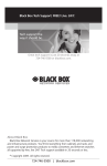
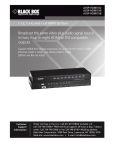
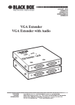
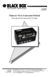
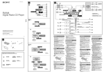
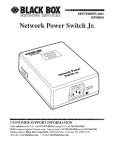
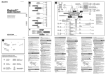
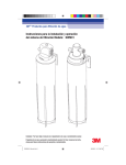
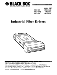
JULY 2006 SW549A SW549AE Remote Console Port + Remote Power Manager Quick Start Guide Port sole Con ote Rem VITY ACTI PWR AR CLE CUSTOMER SUPPORT INFORMATION SET TUS STA DCD RDY 1 2 3 4 5 te emo +R er Pow age Man r 6 ON Order toll-free in the U.S.: Call 877-877-BBOX (outside U.S. call 724-746-5500) FREE technical support 24 hours a day, 7 days a week: Call 724-746-5500 or fax 724-746-0746 Mailing address: Black Box Corporation, 1000 Park Drive, Lawrence, PA 15055-1018 Web site: www.blackbox.com • E-mail: [email protected] REMOTE CONSOLE PORT + REMOTE POWER MANAGER QUICK START GUIDE FEDERAL COMMUNICATIONS COMMISSION AND INDUSTRY CANADA RADIO FREQUENCY INTERFERENCE STATEMENTS This equipment generates, uses, and can radiate radio-frequency energy, and if not installed and used properly, that is, in strict accordance with the manufacturer’s instructions, may cause interference to radio communication. It has been tested and found to comply with the limits for a Class A computing device in accordance with the specifications in Subpart B of Part 15 of FCC rules, which are designed to provide reasonable protection against such interference when the equipment is operated in a commercial environment. Operation of this equipment in a residential area is likely to cause interference, in which case the user at his own expense will be required to take whatever measures may be necessary to correct the interference. Changes or modifications not expressly approved by the party responsible for compliance could void the user’s authority to operate the equipment. This digital apparatus does not exceed the Class A limits for radio noise emission from digital apparatus set out in the Radio Interference Regulation of Industry Canada. Le présent appareil numérique n’émet pas de bruits radioélectriques dépassant les limites applicables aux appareils numériques de la classe A prescrites dans le Règlement sur le brouillage radioélectrique publié par Industrie Canada. EUROPEAN UNION DECLARATION OF CONFORMITY This equipment complies with the requirements of the European EMC Directive 89/336/EEC. 2 REMOTE CONSOLE PORT + REMOTE POWER MANAGER QUICK START GUIDE NORMAS OFICIALES MEXICANAS (NOM) ELECTRICAL SAFETY STATEMENT INSTRUCCIONES DE SEGURIDAD 1. Todas las instrucciones de seguridad y operación deberán ser leídas antes de que el aparato eléctrico sea operado. 2. Las instrucciones de seguridad y operación deberán ser guardadas para referencia futura. 3. Todas las advertencias en el aparato eléctrico y en sus instrucciones de operación deben ser respetadas. 4. Todas las instrucciones de operación y uso deben ser seguidas. 5. El aparato eléctrico no deberá ser usado cerca del agua—por ejemplo, cerca de la tina de baño, lavabo, sótano mojado o cerca de una alberca, etc.. 6. El aparato eléctrico debe ser usado únicamente con carritos o pedestales que sean recomendados por el fabricante. 7. El aparato eléctrico debe ser montado a la pared o al techo sólo como sea recomendado por el fabricante. 8. Servicio—El usuario no debe intentar dar servicio al equipo eléctrico más allá a lo descrito en las instrucciones de operación. Todo otro servicio deberá ser referido a personal de servicio calificado. 9. El aparato eléctrico debe ser situado de tal manera que su posición no interfiera su uso. La colocación del aparato eléctrico sobre una cama, sofá, alfombra o superficie similar puede bloquea la ventilación, no se debe colocar en libreros o gabinetes que impidan el flujo de aire por los orificios de ventilación. 10. El equipo eléctrico deber ser situado fuera del alcance de fuentes de calor como radiadores, registros de calor, estufas u otros aparatos (incluyendo amplificadores) que producen calor. 11. El aparato eléctrico deberá ser connectado a una fuente de poder sólo del tipo descrito en el instructivo de operación, o como se indique en el aparato. 3 REMOTE CONSOLE PORT + REMOTE POWER MANAGER 12. Precaución debe ser tomada de tal manera que la tierra fisica y la polarización del equipo no sea eliminada. 13. Los cables de la fuente de poder deben ser guiados de tal manera que no sean pisados ni pellizcados por objetos colocados sobre o contra ellos, poniendo particular atención a los contactos y receptáculos donde salen del aparato. 14. El equipo eléctrico debe ser limpiado únicamente de acuerdo a las recomendaciones del fabricante. 15. En caso de existir, una antena externa deberá ser localizada lejos de las lineas de energia. 16. El cable de corriente deberá ser desconectado del cuando el equipo no sea usado por un largo periodo de tiempo. 17. Cuidado debe ser tomado de tal manera que objectos liquidos no sean derramados sobre la cubierta u orificios de ventilación. 18. Servicio por personal calificado deberá ser provisto cuando: 4 A: El cable de poder o el contacto ha sido dañado; u B: Objectos han caído o líquido ha sido derramado dentro del aparato; o C: El aparato ha sido expuesto a la lluvia; o D: El aparato parece no operar normalmente o muestra un cambio en su desempeño; o E: El aparato ha sido tirado o su cubierta ha sido dañada. NOM STATEMENT TRADEMARKS USED IN THIS MANUAL BLACK BOX and the Double Diamond logo are registered trademarks of BB Technologies, Inc. Crosstalk is a registered trademark of Digital Communications Associates, Inc. VT100 is a trademark of Digital Equipment Corporation. AT is a registered trademark of International Business Machines Corporation. Netscape Navigator is a registered trademark of Netscape Communications Corporation. JavaScript is a registered trademark of Sun Microsystems, Inc. UNIX is a registered trademark of UNIX System Laboratories, Inc. Any other trademarks mentioned in this manual are acknowledged to be the property of the trademark owners. 5 REMOTE CONSOLE PORT + REMOTE POWER MANAGER WARNINGS AND CAUTIONS Secure Racking If secure racked units are installed in a closed or multi-unit rack assembly, they may require further evaluation by certification agencies. Consider the following items: 1. The ambient temperature within the rack may be greater than the room ambient temperature. Installation should be such that the amount of airflow required for safe operation is not compromised. The maximum temperature for the equipment in this environment is 122°F (50°C). 2. Install the unit so that it doesn’t become unstable from uneven loading. Input Supply Check nameplate ratings to ensure that there is no overloading of supply circuits that could have an effect on overcurrent protection and supply wiring. Grounding Maintain reliable grounding of this equipment. Give particular attention to supply connections when connecting to power strips, rather than direct connections to the branch circuit. Shock Hazard Do not attempt to repair or service this device yourself. Internal components must be serviced by authorized personnel only. Disconnect Power If any of the following events occurs, immediately disconnect the unit from the outlet and contact Black Box at 724-746-5500. 1. The power cord is frayed or damaged. 2. Liquid has been spilled into the device or the device has been exposed to rain or water. Disconnect the Power Supply Cable Before attempting to service or remove this unit, make certain that the power cable is disconnected. 6 WARNINGS AND CAUTIONS Specifications Power Input / Output: Model SW549A (120 VAC) • AC Input: 15 Amps Maximum ▪ Voltage: 100 - 120 VAC, 50/60 Hz ▪ Connector: IEC320-C14 Inlet. • AC Outputs: ▪ Connectors: Four (4) NEMA 5-15 ▪ Load: 15 Total Amps Maximum. Model SW549AE (240 VAC) • AC Input: 10 Amps Maximum ▪ Voltage: 208 - 240 VAC 50/60 Hz ▪ Connector: IEC-320-C14 Inlet. • AC Outputs: ▪ Connectors: Four (4) IEC-320-C13 Outlets. ▪ Load: 10 Total Amps Maximum Network Interface: • Network Port: Ethernet, 10Base-T, RJ-45. Modem Interface: • Phone Line Port: RJ11 RS-232 Interface: • Connectors: Six (6) DB-9M (DTE Pinout.) • Coding: 7 or 8 Bits, Even/Odd/None Parity, 1 or 2 Stop Bits. • Flow Control: Xon/Xoff, RTS/CTS, or None. • Data Rate: 300 bps to 115,200 bps. Physical / Environmental: • Size: ▪ Width: 17" (43.2 cm) - 19" Rack Brackets Included ▪ Depth: 6.5" (16.5 cm) ▪ Height: 1.75" (4.5 cm) One Rack U. • Shipping Weight: 8 Lbs. • Operating Temperature: 32°F to 122°F (0°C to 50°C) • Humidity: 10 - 90% RH 7 REMOTE CONSOLE PORT + REMOTE POWER MANAGER QUICK START GUIDE Quick Start Guide In order to take full advantage of the complete range of features that the Remote Console Port + Remote Power Manager offers, we recommend that you read the user’s manual (it’s in PDF format on the included CDROM) after performing this quick start procedure. Hardware Description Front Panel Remote Console Port + Remote Power Manager CLEAR 1 2 PWR ON SET STATUS RDY 3 4 ACTIVITY 1 DCD 5 2 3 4 5 6 6 Figure 1. Front Panel Components Clear Button: Restarts the Remote Console Port + Remote Power Manager operating program without changing user-selected parameters or breaking port connections. Power Indicator: Lights when power is applied to the unit. Set Button: The Set Button has two functions; it can either be used as a manual On/Off switch for the four switched outlets, or it can also be used to initialize the unit to default parameters. • Manual Switching: To manually switch the outlets Off or On, press and hold the Set Button for approximately three seconds. Note that the Manual Switching function can also be disabled as described in Section 5.5.1 in the user’s guide. • Initialization: To initialize the unit to default parameters, press and hold both the Set and Clear buttons, then release only the Clear Button, wait for the Activity LEDs to flash, and then release the Set Button. Notes: • During initialization, all activity LEDs will flash ON three times. • When the initialization procedure is performed, all command selected parameters will be cleared, and the Remote Console Port + Remote Power Manager will revert to default parameters. 8 REMOTE CONSOLE PORT + REMOTE POWER MANAGER QUICK START GUIDE RDY Indicator: (Ready) Flashes when the unit is ready to receive commands. DCD Indicator: Lights when the Data Carrier Detect signal is present. Activity Indicators: A series of six LEDs, which light to indicate data activity at the corresponding port. Back Panel 6 O 15 AMPS MAX 1 PLUG 1 PLUG 2 PLUG 3 2 PLUG 4 5 3 6 4 3 SYSTEM SETUP PORTS I 1 2 ACT 10BaseT 4 PHONE LINE 5 Figure 2. Back Panel Components (Model SW549A Shown) Power Inlet and Circuit Breaker: An AC inlet and circuit breaker which supply power to the Remote Console Port + Remote Power Manager. Includes cable keeper (not shown.) • Model SW549A (120 VAC): IEC-320-C14, 100 - 120 VAC Power Inlet, 15 Amp Circuit Breaker. • Model SW549AE (230 VAC): IEC-320-C14, 208 - 240 VAC Power Inlet, 10 Amp Circuit Breaker. Switched Plugs and Plug Indicators: Four AC Outlets that can be switched On, Off, Rebooted or set to user-defined Default values in response to user commands. • Model SW549A: Four 100-120 VAC, NEMA 5-15 Outlets with indicator lights. 15 Amps Total Load. • Model SW549AE: Four 208-240 VAC, IEC-320-C13 Outlets with indicator lights. 10 Amps Total Load. 9 REMOTE CONSOLE PORT + REMOTE POWER MANAGER QUICK START GUIDE Serial RS232 Ports: For connection to console ports on target devices. Standard DB9 connectors configured as DTE ports, similar to a serial port on a PC. When connecting a modem, use a standard serial cable. When connecting a PC or other DTE device use a null modem cable. Notes: • Ports 1 is a System Setup Port. In order to ensure local access by system administrators, Supervisor Level command capability cannot be disabled at Port 1, and the Port Mode cannot be set to “Buffer” or “Passive”. • Port 2 can also be used as a Setup Port, providing that the Port Mode is set to Any-to-Any and the Supervisor Mode is enabled. 10Base-T Port (Network Port): An RJ45 Ethernet Port for connection to your TCP/IP network. The 10Base-T Port also features an Activity Indicator flashes to indicate activity at the Network Port. The default IP Address is 192.168.168.168. For more information on Network Port configuration, please refer to Section 5.5.2 in the user’s guide. Phone Line Port (Internal Modem Port): For connection to your phone line. For information regarding modem configuration, please refer to Section 5.5.4 in the user’s guide. Main Power Switch: Applies power to the Remote Console Port + Remote Power Manager. This switch must be “On” in order for the Remote Console Port + Remote Power Manager to function. Note that this switch is not used to set the On/Off status of the switched outlets. Hardware Installation Applying Power Refer to the safety precautions listed on page 5. Connect the power supply cable to the unit’s power inlet, snap the Cable Keeper into place, and then connect the cable to an appropriate power supply. CAUTION: Review the safety precautions listed on Page 6. Note: The Remote Console Port + Remote Power Manager is designed for 100 to 120 VAC operation and the Remote Console Port + Remote Power Manager-CE is designed for 100 to 240 VAC operation. 10 REMOTE CONSOLE PORT + REMOTE POWER MANAGER QUICK START GUIDE When power is applied to the Remote Console Port + Remote Power Manager, the ON LED should light, and the RDY LED should begin to flash. This indicates that the unit is ready to receive commands. Connect your PC to the Manager The Remote Console Port + Remote Power Manager can either be controlled by a local PC Serial Port, controlled via modem, or controlled via TCP/IP network. In order to select parameters, connect ports or control outlets, commands are issued to the Remote Console Port + Remote Power Manager via either the Network Port, Modem Port or a Serial RS232 Port. • Network Port: Connect the Remote Console Port + Remote Power Manager 10Base-T, half duplex network interface to your network. • Serial Port: Use the supplied null modem cable to connect your PC COM port to Serial Port 1 (The System Setup Port.) • Modem: Connect your telephone line to the Remote Console Port + Remote Power Manager Phone Line Port. Communication The Remote Console Port + Remote Power Manager offers two separate user interfaces: the Web Browser Interface and the Text Interface. The Web Browser interface allows you to contact the unit via a TCP/IP network, using a standard, JavaScript enabled web browser. The Text Interface consists of a series of ASCII text menus, which may be accessed via TCP/IP network, Local PC or modem. Notes: • When the unit is shipped from the factory, communications parameters are set as follows: 9600 bps, RTS/CTS Handshaking, 8 Data Bits, One Stop Bit, No Parity. Although the Remote Console Port + Remote Power Manager allows these parameters to be easily redefined, for this Quick Start procedure, it is recommended to configure your communications program to accept the default parameters. • The Remote Console Port + Remote Power Manager features a default IP Address (192.168.168.168) and a default Subnet Mask (255.255.255.0.) This allows initial network access to command mode without first setting up the unit’s network parameters (providing that you are contacting the unit from a node on the same subnet.) When attempting to access the Remote Console Port + Remote Power Manager from a node that is not on the same subnet, please refer to Section 5 in the user’s guide for further configuration instructions. 11 REMOTE CONSOLE PORT + REMOTE POWER MANAGER QUICK START GUIDE 1. Access Command Mode: This procedure differs slightly, depending on whether you’re contacting the Remote Console Port + Remote Power Manager via the Web Browser Interface or Text Interface. a) Web Browser Interface: Start your JavaScript enabled Web Browser. Enter the Remote Console Port + Remote Power Manager’s IP address in your browser address bar and press [Enter]. b) Text Interface: i. Via Telnet: Telnet to the Remote Console Port + Remote Power Manager’s default IP address. ii. Via Local PC: Start your communications program and press [Enter]. iii. Via Modem: Use your communications program to dial the number for the line that is connected to the Remote Console Port + Remote Power Manager's Phone Line Port. 2. Password Prompt: Normally at this point, no user accounts have been defined yet, so if the password prompt is displayed, you can simply press [Enter] or click "OK" to bypass the prompt. However, if you have previously defined one or more passwords, enter the username (Web Interface only) and password and then press [Enter] or click "OK." The Status Screen should be displayed as shown in Figure 3 or Figure 4. Connecting Ports and Switching Outlets Although both the Text Interface and Web Browser Interface allow you to select configuration parameters, the Text Interface is always used when invoking commands to create connections between ports. Although the Web Browser Interface does allow access to outlet switching functions, for this Quick Start procedure, it is recommended to perform the following steps via the Text Interface. If you have previously accessed command mode via the Web Browser Interface, exit command mode (log out), then re-enter command mode using the Text Interface as described in Step 1 above. Proceed as follows to connect ports and switch outlets: 1. 12 Review the Help Menu: At the Text Interface command prompt, type /H and press [Enter] to display the Help Menu, which provides a basic listing of all available Remote Console Port + Remote Power Manager commands. REMOTE CONSOLE PORT + REMOTE POWER MANAGER QUICK START GUIDE Figure 3: Main Status Screen - Web Browser Interface Console Port + Power Manager v1.10a Site ID: 1000 Park Drive, Lawrence, PA PORT | NAME | CMD ACCESS | STATUS | MODE | BUFFER COUNT -----+------------------+----------------+--------+---------+--------------+ 1 | (undefined) | Unlocked | Free | Any | 0 | 2 | (undefined) | Unlocked | Free | Any | 0 | 3 | (undefined) | Unlocked | Free | Any | 0 | 4 | (undefined) | Unlocked | Free | Any | 0 | 5 | (undefined) | Unlocked | Free | Any | 0 | 6 | (undefined) | Unlocked | Free | Any | 0 | 7 | Internal_Modem | Unlocked | Free | Modem | 0 | -----+------------------+----------------+--------+---------+--------------+ PLUG | NAME | BOOT/SEQ DELAY | STATUS | DEFAULT | -----+------------------+----------------+--------+---------+ 1 | (undefined) | 0.5 Secs | ON | ON | 2 | (undefined) | 0.5 Secs | ON | ON | 3 | (undefined) | 0.5 Secs | ON | ON | 4 | (undefined) | 0.5 Secs | ON | ON | -----+------------------+----------------+--------+---------+ “/H” for help. CMS> Figure 4: Main Status Screen - Text Interface 13 REMOTE CONSOLE PORT + REMOTE POWER MANAGER QUICK START GUIDE 2. Creating Connections Between Ports: The Remote Console Port + Remote Power Manager can perform two different types of port connections; Resident Connections and Third Party Connections: a) b) Resident Connection: Your resident port issues a /C command to connect to a second port. i. To connect your resident port to Port 3, type /C 2 [Enter]. While you are connected to Port 3, the unit will not recognize additional commands issued via your resident port. However, the unit will recognize a Resident Disconnect Sequence issued at either connected port. ii. Issue the Resident Disconnect Sequence (Logoff Sequence); type ^X (press [Ctrl] and [X] at the same time). Third Party Connection: Your resident port issues a /C command to create a connection between two other ports. i. ii. To connect Port 3 to Port 4, type /C 3 4 [Enter]. While Ports 3 and 4 are connected, your resident port will still recognize commands. Type /S [Enter] to display the Status Screen. The "STATUS" column should now list Ports 3 and 4 as connected and the other ports as "Free". iii. Issue a Third Party Disconnect command; type /D 3 [Enter]. The unit will display the "Are you Sure (y/n)?" prompt. Type y and press [Enter] to disconnect. iv. 14 Type /S [Enter] to display the Status Screen. The "STATUS" column should now list Ports 3 and 4 as "Free". REMOTE CONSOLE PORT + REMOTE POWER MANAGER QUICK START GUIDE 3. 4. Controlling Outlets: You may wish to perform the following tests in order to make certain that the switched outlets are functioning properly. a) Reboot Outlet: At the command prompt, type /BOOT 1 and press [Enter]. The status indicator for Plug 1 should go Off, pause for a moment and then go back On, indicating that the boot cycle has been successfully completed. b) Switch Outlet Off: At the command prompt, type /OFF 1 and then press [Enter]. The status indicator for Plug 1 should go Off, indicating that the command has been successfully completed. Leave Plug 1 in the "Off" state, and then proceed to the next step. c) Switch Outlet On: At the command prompt, type /ON 1 and press [Enter]. The status indicator for Plug 1 should then go back On, indicating that the command has been successfully completed. Exit Command Mode: To exit command mode, type /X and press [Enter]. When the "Sure" prompt is displayed, type Y and press [Enter]. This completes the Quick Start instructions for the Remote Console Port + Remote Power Manager. Prior to placing the unit into operation, it is recommended to refer to the remainder of this user’s guide for important information regarding advanced configuration capabilities and more detailed operation instructions. 15 © Copyright 2006. Black Box Corporation. All rights reserved. 1000 Park Drive • Lawrence, PA 15055-1018 • 724-746-5500 • Fax 724-746-0746