1
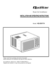
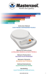
Room Air Conditioner
INSTALLATION AND OPERATING INSTRUCTIONS
Model:
HQ-2052UH
Please read these operating instructions thoroughly
before using your air conditioner and keep for future
reference.
For assistance, please call: 1-800-211-PANA(7262) or
Register your product at : http://www.panasonic.com/register
CW382820391E
Safety Precautions
Safety Precautions
Safety Precautions .............3
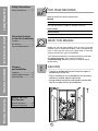
FOR YOUR RECORDS
Write the model and serial numbers here:
Model #
Serial #
You can find them on a label on the side of the unit.
Dealer's Name
Date Purchased
Before you call for service...
Features and Installation
About the Controls on the Air Conditioner
Staple your receipt here for proof of purchase.
About the Controls
on the Air Conditioner
Controls..............................5
Air direction ........................7
Care and Maintenance ......7
READ THIS MANUAL
Inside you will find many helpful hints on how to use and
maintain your air conditioner properly. Just a little preventive
care on your part can save you a great deal of time and
money over the life of your air conditioner.
You'll find many answers to common problems in the chart
of troubleshooting tips. If you review our chart of
Troubleshooting Tips first, you may not need to call for
service at all.
Features
and Installation
Features .............................8
Window Requirements .......9
Electrical Data ..................11
CAUTION
• Contact an Authorized Service Center for repair or
maintenance of this unit.
• The air conditioner is not intended for use by young
children or invalids without supervision.
• Young children should be supervised to ensure that
they do not play with the air conditioner.
Before You Call
For Service...
Normal Operation.............12
Abnormal Operation .........12
2
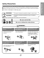
To prevent injury to the user or other people and property damage, the following instructions must be followed:
■ Incorrect operation will cause harm or damage. The seriousness is classified by the following indications.
■ Because of the weight of the product, it is recommended that you have a helper to assist in the installation.
■ Use Caution! Sharp Edges! See Warning, page 4.
WARNING
: This symbol indicates the possibility of death or serious injury.
CAUTION
symbol indicates the possibility of injury or damage to
: This
property
■ Meanings of symbols used in this manual are as shown below.
Be sure not do this.
Be sure to follow the instructions.
WARNING
Plug in the power plug
properly.
Do not operate or stop the
unit by inserting or pulling
out the power plug.
Do not damage or use an
unspecified power cord.
• Otherwise, it will cause electric
shock or fire due to heat
generation.
• It will cause electric shock or fire
due to heat generation.
• It will cause electric shock or fire.
• If the power cord is damaged, it must
be replaced by the manufacturer or
its service agent or a similarly
qualified person in order to avoid a
hazard.
Do not modify the length of
the power cord or use an
extension cord.
Do not operate with wet
hands or in damp
environment.
Do not direct air flow at room
occupants.
• It will cause electric shock.
• This could lead to health
problems.
• It will cause electric shock or fire
due to heat generation.
3
Safety Precautions
Safety Precautions
Safety Precautions
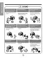
When the air filter is to be
removed, do not touch the
metal parts of the unit.
Do not clean the air
conditioner with water.
When the unit is to be
cleaned, switch the unit off,
and unplug it.
• They are sharp and may cause
an injury.
• Water may enter the unit and
degrade the insulation. It may
cause an electric shock.
• Since the fan rotates at high
speed during operation, it may
cause an injury.
Do not operate the unit
without the air filter or when
the front intake grille has
been removed.
Do not put a pet or house
plant where it will be
exposed to direct air flow.
Do not use the unit for any
other purpose than its
intended use.
• It could cause dust to
accumulate on the heat
exchanger.
• This could injure the pets
or plants.
• Do not use this air conditioner to
preserve precision devices, food,
pets, plants, or art objects.
It may cause deterioration of
quality, etc.
Do not operate switches
with wet hands.
Do not apply an insecticide
or flammable spray.
SHARP EDGES!
• It may cause an electric shock.
• It may cause a fire or damage of
the cabinet.
• Use caution when handling the
case. Grip it firmly and do not allow
it to slip while holding it.
• Use heavy gloves to handle the
case if necessary.
Sharp edges
4
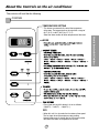
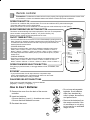
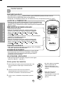
About the Controls on the air conditioner
The controls will look like the following.
Controls
TEMPERATURE SETTING
• This button can automatically control the temperature
of the room. The temperature can be set within a range of
60°F (16°C) to 86°F (30°C) by 1°F (1°C).
Select the lower number for lower temperature of the room.
MODE
ECONOMY, FAN and DRY.
is
• Every time you push this button it is set as follows.
{High(F2) → Low(F1) → High(F2)...}.
DRY
• When this unit is in dry mode, the fan rotates at low speed.
The fan stops when the compressor stops cooling.
Approximately every 3 minutes the fan will turn on and the
unit checks the room air temperature to set itself.
5
About the Controls on the Air Conditioner
°F
hr
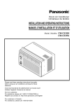
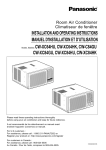
Remote controller
Precaution: The Remote Controller will not function properly if strong light strikes the sensor window of the
air conditioner or if there are obstacles between the Remote Controller and the air conditioner.
OPERATION BUTTON
• To turn the air conditioner ON, push the button. To turn the air conditioner OFF, push the button again.
• This button takes priority over any other buttons.
• When you first turn it on, the air conditioner is on the High cool mode and the temp. at 72°F (22°C).
About the Controls on the Air Conditioner
ROOM TEMPERATURE SETTING BUTTON
This button can automatically control the temperature of the room. The temperature
can be set within a range of 60°F to 86°F by 1°F. (16°C to 30°C by 1°C)
Select the lower number for lower temperature of the room.
OPERATION
ON/OFF TIMER BUTTON
• You can set the time when the unit will turn on or turn off automatically by pressing the timer
button. If the unit is in operation, this button controls the time it will be turned off. If the unit is
in off state, this button controls the time it will start. Every time you push this button, the
remaining time will be set as follows:
- STOPPING OPERATION
• Every time you push this button, when the air conditioner is operating, timer is set as
follows : (1Hour → 2Hours → 3Hours → 4Hours → 5Hours → 6Hours → 7Hours →
8Hours → 9Hours → 10Hours → 11Hours → 12Hours → 0Hour → 1Hour → 2Hours → ...)
• The Setting Temperature will be raised by 2°F (1°C) 30 min. later and by 2°F (1°C) after
another 30 min.
- STARTING OPERATION
• Every time you push this button, when the air conditioner is not operating, timer is set as
follows : (1Hour → 2Hours → 3Hours → 4Hours → 5Hours → 6Hours → 7Hours →
8Hours → 9Hours →10Hours → 11Hours → 12Hours → 0Hour → 1Hour → 2Hours → ...)
TEMP
TIMER
MODE
FAN SPEED
ECONOMY
OPERATION MODE SELECTION BUTTON
Every time you push this button, it will toggle between COOL, ECONOMY, FAN
and DRY.
ECONOMY
• If you push this button, the fan stops when the compressor stops
cooling. Approximately every 3 minutes the fan will turn on and check
the room air to determine if cooling is needed.
FAN SPEED SELECTION BUTTONS
Every time you push this button, it is set as follows.
{High(F2) → Low(F1) → High(F2)...}.
How to Insert Batteries
1. Remove the cover from the back of the remote
controller
2. Insert two batteries.
• Be sure that the (+) and (-) directions are correct.
• Be sure that both batteries are new.
3. Re-attach the cover.
6
• Do not use rechargeable
batteries. Such batteries
differ from standard dry
cells in shape, dimensions,
and performance.
• Remove the batteries from
the remote controller if the
air conditioner is not going
to be used for an extended
length of time.
Additional controls and important information.
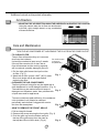
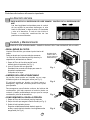
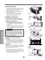
Air Direction
• ADJUSTING THE AIR DIRECTION USING THE HORIZONTAL AIR-DEFLECTOR CONTROL
Using the control tabs, the air flow can be directed
to the left, right, straight ahead, or any combination
of these directions.
TURN THE AIR CONDITIONER OFF AND REMOVE THE PLUG FROM THE POWER OUTLET.
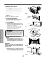
• TO CLEAN FILTER
The air filter will become dirty as it removes
dust from the inside air.
It should be washed at least every 2 weeks.
If the air filter remains full of dust, the air
flow will decrease and the cooling capacity
will be reduced, possibly damaging the unit.
Do not force open
or open too
far (about 56°)
1. Pull the inlet grille forward and pull out the
air filter. (Fig. 1)
2. Wash the air filter in warm 104°F (40°C) water.
Be sure to shake off all the water before
replacing the filter.
Fig. 1
• CLEANING THE AIR CONDITIONER
The front grille and inlet grille may be wiped with a
cloth dampened in a mild detergent solution. (Fig. 2)
The cabinet may be washed with mild soap or
Fig. 2
detergent and lukewarm water, then polished with
a liquid wax used for appliances.
To ensure continued peak efficiency, the condenser
coils (outside of unit) should be checked
periodically and cleaned if clogged with soot or
Fig. 3
dirt from the atmosphere.
• HOW TO REMOVE THE FRONT GRILLE
1. Pull the inlet grille forward.
2. Remove the screw securing the front grille. (Fig. 3)
3. Push the grille up from the bottom and pull
the top of the grille away from the case as
the top tabs lift out of their slots. (Fig. 4)
Fig. 4
7
About the Controls on the Air Conditioner
Care and Maintenance
Features and Installation
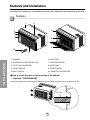
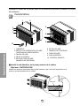
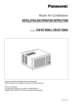
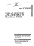
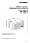
Learning parts name prior to installation will help you understand the installation procedure.
Features
1
9
4
3
2
7
6
5
10
Features and Installation
8
1. CABINET
6. AIR FILTER
2. HORIZONTAL AIR DEFLECTOR
7. CONTROL BOARD
3. COOL AIR DISCHARGE
8. AIR INTAKE
4. FRONT GRILLE
9. UPPER GUIDE
5. INLET GRILLE
10. REMOTE CONTROLLER
■ How to install wire net on the back side of the cabinet
(Optional : CW353020031B)
Insert the rear grill wire ends into the 4 respective slots provided along the groove at the back of unit
Groove
Wire net
8
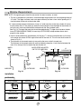
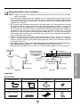
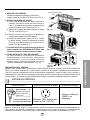
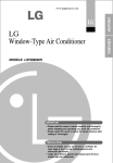
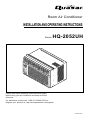
Window Requirements
NOTE: All supporting parts should be secured to firm wood, masonry, or metal.
1. This unit is designed for installation in standard double hung windows with actual opening widths of
22" to 36". The upper and lower sash must open sufficiently to allow a clear vertical opening of 13"
from the bottom of the sash to the window stool.
2.If a storm window presents interference, fasten a 2" wide wood strip to the inner window sill across
the full width of the sill. The wood strip should be thick enough to raise the height of the window sill
so that the unit can be installed without interference by the storm window frame.
See Fig. 5-2. The top of the wood strip should be approximately 3/4" higher than the storm window
frame (STORM WINDOW FRAME) or wood strip (OUTDOORS) to help condensation to drain
properly to the outside.
3. Install a second wood strip (approximately 18" long by 11/2" wide and same thickness as first strip)
in the center of the outer sill flush against the back off the inner sill. This will raise the L bracket as
shown in Fig. 5-2.
4. The thickness of the second wood strip may not be the same as the first wood strip.
The thickness of the second wood strip must be defined to keep the 3/4 inch distance between the
inner sill or the top of the first wood strip and the outer sill.
WOOD STRIP MOUNTED
ON TOP OF INNER SILL
INNER
SILL
1"
3
/4"
CLEARANCE
INNER
SILL
WOOD STRIP
FOR L BRACKET
OUTER
SILL
OUTER
SILL
INDOORS
OUTDOORS
INDOORS
Fig. 5-1
OUTDOORS
Fig. 5-2
Installation
HARDWARE
TYPE B: Qty:5
(WOOD SCREW)
TYPE C: Qty:3
(L BRACKET)
DRAIN PIPE
Qty:1
5/8"
(16mm)
25/64"
(10mm)
TYPE A: Qty:11
(SHORT SCREW)
TYPE D: Qty:1
(SEAL STRIP)
TYPE E: Qty:1
(SASH SEAL)
(Adhesive backed)
(Not adhesive backed)
TYPE F: Qty:2
(GUIDE PANEL)
9
TYPE G: Qty:1
(SUPPORT BRACKET)
Features and Installation
STORM
WINDOW
FRAME
A. BEFORE INSTALLATION
1. Insert the guide panels into the guides of the air
conditioner. Fasten the curtains to the unit with
screws (TYPE A), as shown Fig. 6.
2. Cut the adhesive-backed seal strip (TYPE D) to the
window width.
Remove the backing from the seal strip and attach
the seal strip to the underside of the bottom
window. (Fig. 7)
TYPE A
Fig. 6
SEAL STRIP
(TYPE D)
B. NOW START INSTALLATION
1. LOCATING UNIT IN A WINDOW
Open the window and mark center line on the
center of the inner sill, as shown in Fig. 8.
Fig. 7
2. ATTACH L BRACKET
a. Install the L brackets behind the inner window
sill, with short side of bracket as shown. Use the
2 screws (TYPE A) provided.
b. The bracket helps to hold the unit securely in
place. Be sure to place bracket edge flush
against back of inner sill. See Fig. 9.
Features and Installation
TYPE A
CENTER LINE
INNER SILL
ROOM SIDE
Fig. 8
INNER SILL
TYPE A
OUTER SILL
CAUTION
INSIDE
CENTER LINE
During the following step, hold unit firmly until
window sash is lowered to top channel behind
side panel frames. Personal injury or property
damage may result if unit falls from window.
8"
8"
OUTSIDE
3. INSTALL THE AIR CONDITIONER IN THE
WINDOW
a. Carefully lift the air conditioner and slide it into
the open window. Make sure the bottom guide of
the air conditioner drops into the notches of the
L bracket. See Fig. 9.
IMPORTANT :
When the air conditioner drops into the L bracket, the
air conditioner will be centered in window opening as
shown in Fig. 10.
b. While steadying the air conditioner, carefully
bring the window sash down behind the upper
guide of the air conditioner, as shown in Fig. 11.
Fig. 9
L BRACKET
WINDOW FRAME
UPPER GUIDE
SEAL
ABOUT 1/4"
BOTTOM
GUIDE
Fig. 11
10
CENTER LINE
Fig. 10
L BRACKET
4. SECURE THE GUIDE PANELS
Extend the guide panels (TYPE F) to fill the window
opening using 4 screws (TYPE B) to secure them, as
shown in Fig. 12.
5. INSTALL THE SASH SEAL AND SASH LOCK
a. Cut the sash seal (TYPE E) to the window width.
Stuff the sash seal between the glass and the
window to prevent air and insects from getting into
the room, as shown in Fig. 12.
b. Fasten the L bracket using a screw (TYPE A), as
shown in Fig. 12.
L BRACKET
TYPE A
SASH SEAL
(TYPE E)
TYPE B
Fig. 12
6. a. Remove the screws that secure the cabinet and
base pan in the right side.
b. Fasten the support bracket (TYPE G) using a
removed screw. Attach the support bracket (TYPE G)
in the inner window sill with a screw (TYPE B), as
shown Fig. 13.
7. Window installation of room air conditioner is now
completed. See ELECTRICAL DATA for attaching
power cord to electrical outlet.
TYPE B
Support Bracket (TYPE G)
Fig. 13
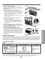
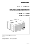
C. HOW TO SECURE THE DRAIN PIPE
Hang
DRAIN PIPE
Push
DRAIN CAP
Fig. 14
REMOVAL FROM WINDOW
Turn the air conditioner off, disconnect the power cord, remove the Support Bracket, L bracket and the screws
installed through the top and bottom of the guide panels, and save for reinstallation later. Close the guide panels.
Keeping a firm grip on the air conditioner, raise the sash, and carefully tilt the air conditioner backward, draining
any condensate. Lift the air conditioner from the window and remove the sash seal from between the windows.
Electrical Data
Line Cord Plug
Use Wall Receptacle
Do not under any
circumstances cut
or remove the
grounding prong
from the plug.
Power supply cord with
3-prong grounding plug
Power Supply
Use 15 AMP, time
delay fuse or circuit
breaker.
Standard 125V, 3-wire grounding
receptacle rated 15A, 125V AC
USE OF EXTENSION CORDS
Because of potential safety hazards, we strongly discourage the use of an extension cord. However, if you wish to
use an extension cord, use a CSA certified/UL-listed 3-wire (grounding) extension cord, rated 15A, 125V.
11
Features and Installation
In humid weather, excess water may cause the BASE
PAN to overflow. To drain the water, remove the
DRAIN CAP and secure the DRAIN PIPE to the rear
hole of the BASE PAN. (Fig. 14) Press the drain pipe
into the hole by pushing down and away from the fins
to avoid injury.
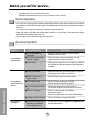
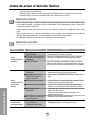
Before you call for service...
Troubleshooting Tips save time and money!
Review the chart below first and you may not need to call for service.
Normal Operation
• You may hear a pinging noise caused by water being picked up and thrown against the condenser
on rainy days or when the humidity is high. This design feature helps remove moisture and improve
efficiency.
• You may hear the relay click when the compressor cycles on and off.
• Water will collect in the base pan during high humidity or on rainy days. The water may overflow
and drip from the outdoor side of the unit.
• The fan may run even when the compressor does not.
Abnormal Operation
Problem
Air conditioner
does not start
Before you call for service...
Air conditioner
does not cool as it
should
Air conditioner
freezing up
Possible Causes
What To Do
■ The air conditioner is
unplugged.
• Make sure the air conditioner plug is pushed
completely into the outlet.
■ The fuse is blown/circuit
breaker is tripped.
• Check the house fuse/circuit breaker box and
replace the fuse or reset the breaker.
■ Power failure.
• When power is restored, wait 3 minutes to restart the
air conditioner to prevent tripping of the compressor
overload.
■ Airflow is restricted.
• Make sure there are no curtains, blinds, or furniture
blocking the front of the air conditioner.
■ TEMP Control set to a
higher number.
• Set the TEMP Control to a lower number.
■ The air filter is dirty.
• Clean the filter at least every 2 weeks.
See the operating instructions section.
■ The room may have been
hot.
• When the air conditioner is first turned on
you need to allow time for the room to cool down.
■ Cold air is escaping.
• Check for open furnace floor registers
and cold air returns.
• Set the air conditioner's vent to the closed position.
■ Cooling coils have iced up.
• See Air Conditioner Freezing Up below.
■ Ice blocks the air flow and
stops the air conditioner
from cooling the room.
• Set the mode control at High Fan or High Cool with
the high temperature.
12
Memo
13
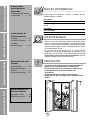
Precauciones Importantes de seguridad
Instrucciones de Funcionamiento
Instrucciones de
Funcionamiento
Antes de avisar al Servicio Técnico
Requerimientos de la Ventana
Precauciones
Importantes de
Seguridad
Precauciones Importantes
de seguridad ....................15
PARA SU INFORMACION
Escriba aquí los números de serie y modelo de las
unidades exterior e interior:
Nº de Modelo
Nº Serie
Los números figuran en una etiqueta en el lateral de cada
unidad.
Distribuidor
Fecha de compra
Controles .........................17
La dirección del aire ........19
Cuidado y
Mantenimiento.................19
Requerimientos de la
Ventana
Características .................20
Requerimientos de la
Ventana ...........................21
Informacion Electrica........23
Adjunte su recibo aquí para probar que lo adquirió.
LEA ESTE MANUAL
• Aquí encontrará numerosas sugerencias sobre cómo
utilizar y mantener adecuadamente su acondicionador de
aire. Con unos cuantos cuidados preventivos se puede
ahorrar mucho tiempo y dinero a lo largo de la vida útil de
su acondicionador de aire.
• En la tabla de sugerencias para la resolución de
problemas encontrará respuestas a la mayoría de los
problemas más comunes. Si consulta primero la tabla de
Sugerencias para la resolución de problemas, quizá ni
siquiera necesite avisar al servicio técnico.
PRECAUCION
• Consulte con el servicio técnico autorizado sobre la
reparación o el mantenimiento de esta unidad.
• El acondicionador de aire no debe ser utilizado por
niños pequeños o personas inestables sin
supervisión.
• Es preciso vigilar a los niños pequeños para
asegurarse de que no juegan con el acondicionador
de aire.
Antes de Avisar Al
Servicio Técnico
Operacíon normal ............24
Operacíon anormal ..........24
14
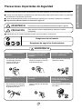
Para prevenir tanto lesiones al usuario u otras personas como daños materiales, es preciso seguir estas instrucciones:
■ El manejo incorrecto debido a la inobservancia de estas instrucciones puede causar lesiones o daños cuya gravedad
está clasificada en las siguientes indicaciones.
■ A cause del peso pesado del producto, se recomienda que usted tenga a un ayudante a participa en la instalación.
■ Tenga Precaución! Bordes Afilados! Ver Advertencia, página 16.
ADVERTENCIA
Este símbolo indica la posibilidad de lesiones mortales o graves.
PRECAUCION
Este símbolo indica la posibilidad de lesiones o daños
materiales.
■ El significado de los símbolos utilizados en este manual se indica a continuación.
Asegúrese de no hacerlo.
Asegúrese de seguir las instrucciones.
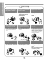
ADVERTENCIA
Conecte correctamente el
enchufle
No opere o pare la unidad
insertando o tirando del
enchufe
No dañe o utilize un cable
eléctrico inadecuado
• De otra forma, ello ocasionaría
una descarga eléctrica o
incendio a causa de la
generación de calor.
• Ello ocasionaría una descarga
eléctrica o incendio a causa de
la generación de calor.
• Ello ocasionaría una descarga
eléctrica o incendio.
No modifique el largo del cable
eléctrico.
No lo maneje con las manos
humedas
No exponga durante mucho
tiempo la piel al aire frío
procedente directamente del
acondicionador.
• Ello ocasionaría una descarga
eléctrica o incendio a causa de
la generación de calor.
• Puede ocasionar una descarga
eléctrica.
• Esto podría dirigir al problema
de la salud.
15
Precauciones Importantes de seguridad
Precauciones Importantes de Seguridad
Precauciones Importantes de seguridad
PRECAUCION
Cuando se vaya a quitar el
filtro de aire no toque las
partes metálicas de la unidad
interior.
No limpie el acondicionador
de aire con agua.
Cuándo la unidad deberá ser
limpiada, cambia la unidad
lejos, y lo quita.
• Esto podría causar heridas.
• El agua podría entrar en la
unidad y degradar el aislamiento.
También podría causar una
sacudida eléctrica.
• Puesto que el ventilador gira a
alta velocidad durante la
operación, podría ocasionar
heridas.
No opere sin el filtro de aire o
cuando la rejilla frontal de toma
de aire haya sido removida.
No ponga un animal doméstico
ni una planta donde quede
directamente expuesto al flujo
de aire.
No lo utilice para propósitos
especiales.
• Podría causar acumulamiento de
polvo en el intercambiador de
calor.
• Esto podría dañar al animal o a
la planta.
• No utilice este acondicionador de
aire para conservar dispositivos de
precisión, alimentos y objetos de
arte; no ponga tampoco animales y
plantas cerca de él. Esto podría
deteriorar la calidad, etc.
No manipule los
interruptores con las manos
mojadas.
No aplique aerosoles con
insecticida o productos
inflamables.
• Esto podría causar una sacudida
eléctrica.
• Esto podría causar un incendio o
deformar la caja.
BORDES AFILADOS!
• Tenga precaución al majenar la
carcasa. Agárrelo firmemente y no
permita que se deslice mientras lo
mantiene.
• Utilice guantes gruesas para manejar la
carcasa según la necesidad.
Bordes
afilados
16
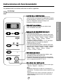
Instruccionnes de Funcionamiento
La apariencia de los controles será como uno de los siguientes.
Controles
°F
hr
• Cada vez que presione este botón, este señalará entre
COOL, ECONOMY, FAN y DRY.
- OPERACIÓN DE PARADA:
• Cada vez que presione este botón, cuando el sistema esté
operando, el marcador de tiempo se ajustará de la siguiente
manera: (1Hora → 2 Horas → 3 Horas → 4 Horas → 5 Horas →
6 Horas → 7 Horas → 8 Horas → 9 Horas → 10 Horas →
11 Horas → 12 Horas → Cancelar).
• La temperatura de ajuste se elevará 2˚F (1°C), 30 minutos
después, y otros 2˚F (1°C) media hora después.
- OPERACIÓN DE INICIACIÓN:
• Cada vez que presione este botón, cuando el sistema esté
operando, el marcador de tiempo se ajustará de la siguiente
manera: (1Hora → 2 Horas → 3 Horas → 4 Horas → 5 Horas
6 Horas → 7 Horas → 8 Horas → 9 Horas → 10 Horas →
11 Horas → 12 Horas → Cancelar).
• Para ENCENDER el sistema presione el botón, y para
APAGARLO presione el botón otra vez.
• Este botón tiene prioridad sobre todos los otros botones.
• Cuando Ud. Io enciende por primera vez, el sistema está
en el y la temperatura es de 72˚F (22°C).
• Cada vez que presione este botón, el ajuste es como sigue.
{Alto (F2) → Bajo (F1) → Alto (F2)...}.
DRY
• Cuando esta unidad se torna al modo seco, el ventilador gira en
velocidad lenta. El ventilador se detiene cuando el compresor se para
de enfriar.
Aproximadamente cada 3 minutos se encenderá el ventilador y la
unidad comprueba la temperatura del aire de la habitación para
ajustarse a si mismo.
17
Instrucciones de Funcionamiento
• Este botón puede controlar la temperatura del cuarto
automáticamente. La temperatura se puede ajustar de grado
en grado, desde 60˚F hasta 86˚F cada 1˚F (16°C hasta 30°C
cada 1°C). Seleccione el número más bajo para la
temperatura másbaja en el cuarto.
Control remoto
ENECNDIDO/APAGADO
• Para ENCENDER el sistema presione el botón, y para APAGARLO presione el botón otra vez.
• Este botón tiene prioridad sobre todos los otros botones.
• Cuando Ud. Io enciende por primera vez, el sistema está en el y la temperatura es de 72˚F (22°C).
Instrucciones de funcionamiento
AJUSTE DE LA TEMPERATURA
• Este botón puede controlar la temperatura del cuarto automáticamente.
La temperatura se puede ajustar de grado en grado, desde 60˚F (16°C)
hasta 86˚F (30°C). Seleccione el número más bajo para la temperatura más
baja en el cuarto.
OPERATION
MARCADOR DE ENCENDIDO/APAGADO
- OPERACIÓN DE PARADA:
• Cada vez que presione este botón, cuando el sistema esté
operando, el marcador de tiempo se ajustará de la siguiente
manera: (1Hora 2 Horas 3 Horas 4 Horas 5 Horas
6 Horas 7 Horas 8 Horas 9 Horas 10 Horas 11 Horas
12 Horas Cancelar).
• La temperatura de ajuste se elevará 2˚F (1°C), 30 minutos después,
y otros 2˚F (1*C) media hora después.
- OPERACIÓN DE INICIACIÓN:
• Cada vez que presione este botón, cuando el sistema esté
operando, el marcador de tiempo se ajustará de la siguiente
manera: (1Hora 2 Horas 3 Horas 4 Horas 5 Horas
6 Horas 7 Horas 8 Horas 9 Horas 10 Horas 11 Horas
12 Horas Cancelar).
TEMP
TIMER
MODE
FAN SPEED
ECONOMY
FRÍO/VENTILADOR/SECO
• Cada vez que presione este botón, las palabras COOL, ECONOMY,
FAN y DRY aparecerán alternadamente.
AHORRADOR DE ENERGÍA
El ventilador se detiene cuando el compressor no sigue enfriando.
• Aproximadamente cada 3 minutos el ventilador se encenderá,
y necesitará verificar la temperatura del cuarto para saber si
es necesario más enfriamiento.
VELOCIDAD DEL VENTILADOR
• Cada vez que presione este botón, el ajuste es como sigue.
{Alto (F2) → Bajo (F1) → Alto (F2)...}
Cómo poner las baterías
1. Quite la tapa de la parte posterior del telemando. Para
ello haga deslizar la tapa según la dirección del la
flecha.
• No utilice baterís recargables,
éstas son diferentes de
forma, de dimensión y uso
respecto a las baterías secas
usuales.
2. Introduzca las dos AAA célula seca baterías,
asegurándose de que las direcciones (+) y (-) estén
colocadas correctament. Use baterías nuevas.
3. Volver a cerrar, resbalando la tapa hasta la posición
inicial.
18
• Seque las baterías del
telemando cuando el
acondicionador no vaya a ser
usado durante un largo
período.
Controles adicionales e informacion importante.
La dirección del aire
• PARA AJUSTAR LA DIRECCION DEL AIRE USANDO CONTROL DE LA DIRECCION DEL
AIRE
Las dos lengüetas horizontales para el control
de las rejillas le permiten descargar el aire
hacia la izquierda, o algo de aire a la izquierda
y otro a la derecha, o todo el aire hacia el
frente, o cualquier combinación de las
posiciones mencionadas.
Cuidado y Mantenimiento
APAGUE EL AIRE ACONDICIONADO Y SAQUE EL ENCHUFE DEL TOMA CORRIENTE DE LA PARED.
• PARA LIMPIAR EL FILTRO
No debe forzar
a abrir o abrir a
lo lejos. (aproxim
adamente 56°)
Fig. 1
• LIMPIEZA DEL AIRE ACONDICINADO
La parrilla frontal puede ser limpiada con un trapo
húmedo mojado en un detergente suave (ver Fig. 2).
El gabinete puede ser lavado con jabón suave o
detergente y agua tibia, entonces pulido Cera Liquida
para aparatos.
Para asegurarse una eficiencia continua, las bobinas del
condensador (del lado expuesto al exterior) debe ser
revisado y lavado periódicamente sea por que se tranque
con basura o polvo de la atmosférico.
Fig. 2
Fig. 3
• COMO REMOVER LA PARILLA FRONTAL
1. Saque el Filtro de Aire halando hacia la izquierda.
2. Saque el tornillo que asegura la Parrilla Frontal (ver Fig. 3).
3. Suelte el lado izquierdo primero.
Después cuidadosamente hale desde la parte de
arriba y empuje hacia la derecha. Las lengüetas están
aseguradas (ver Fig. 4).
19
Fig. 4
Requerimientos de la Ventana
Limpie el Filtro del Aire, que extrae el polvo interior del
cuarto.
Debe ser lavado por lo menos cada dos semanas.
Un filtro de Aire sucio disminuye el flujo de aire y la
capacidad de enfriamiento se reduce.
1. Saque el Filtro de Aire de la parrilla frontal
halando hacia la izquierda (ver Fig. 1).
2. Lave el Filtro de Aire con agua tibia.
Sacúadalo bien cuando esté limpio para sacar la
humedad completamente.
Colóquelo en su lugar.
Aprender el nombre de las partes antes de la instalación le ayudará a entender el proceso
de instalación.
Características
1
9
4
3
2
7
6
5
10
Requerimientos de la Ventana
8
1. GABINETE
6. FILTRO DE AIRE
2. DEFLECTOR HORIZONTAL DE AIRE
(VENTANILLAS VERTICAKLES)
7. TABLEAU DE CONTROLE
3. SALIDA DE AIRE
8. TOMA DE AIRE
9. GUÍA SUPERIOR
4. REJILLA FRONTAL
10. CONTROL REMOTO
5. RECOLECTOR DE AIRE
(BANDEJA DE ENTRADA)
■ Instalar la red alámbrico en la parte posterior de la cabina
(Opcional : CW353020031B)
Inserte los extremos de alambre de la rejilla trasera en las 4 ranuras respectivas en el
canal en la parte posterior de la unidad
Channel
tube
Wire net
20
Requerimientos de la ventana
NOTA: Todas las partes que soportan la ventana deben de estar bien fijas a madera,
metal, o cemento.
1. La unidad está diseñada para ser instalada en una ventana doble con anchos entre 22"
y 36". El borde superior e inferior deben de estar lo suficientemente abierto para permitir
un espacio vertical de por lo menos 13" de la parte inferior de la ventana hasta la parte
superior de la ventana.
2. Si la sobre-ventana estorba colóquese una tira de madera de 2" pulg de ancho a lo largo
del descanso de la ventana por la parte que de internamente al cuarto, y en toda su
extensión. La tira de madera debe ser lo suficientemente gruesa para elevar el descanso
de la ventana, de tal manera que la unidad de aire acondicionado pueda ser intalada sin
interferencia del marco de la sobre-ventana (storm window). Ver Fig. 5-2. La parte
superior de la tira de madera debe estar aproximadamente a 3/4" de pulg más alta que el
marco de la sobre ventana, (storm window) para ayudar a que el agua de condensación
de la unidad fluya hacia afuera.
3. Instale una segunda tira de madera (aproximadamente 18" pulg. de largo, 1-1/2" pulg de
ancho y mismo espesor que la primeratira de madera) en el centro del descanso
exterior, póngala contra la parte posterior del descanso interior. Esto elevará la ménsula
L como en la Fig. 5-2.
4. Si la distancia entre "FRANJA DE MADERA MONTADA SOBRE LA PARTE SUPERIOR
DEL DESCANSO INTERIOR" y "TIRA DE MADERA PARA LA MENSULA L Y
MENSULA DE ANTEPECHO" es mas que 1", dos tiras de modetra no son necessarias.
ANTEPECHO
INTERIOR
1" MAX.
ANTEPECHO
INTERIOR
ANTEPECHO
INTERIOR
EXTERIOR
VENTANA DE
HOJA DOBLE
TIRA DE MADERA
PARA LA MENSULA
L Y MENSULA DE
ANTEPECHO
INTERIOR
Fig. 5-1
3
/4"-PULG
DE SEPARACION
ANTEPECHO
EXTERIOR
Fig. 5-2
Instalacion
MATERIALES
TIPO B: 5
(TORNILLO MEDIANO)
TIPO C: 3
(EL PARÉNTESIS L)
TAPA DEL DESAGÜE: 1
5/8"
(16mm)
25/64"
(10mm)
TIPO A: 11
(TORNILLO CORTO)
TIPO D: 1
(BANDA ADHESIVA)
TIPO E: 1
(BANDA DEL MARCO)
(Adhesivo posterior)
(No adhesivo posterior)
TIPO F: 2
(PANEL GUÍA)
21
TIPO G: 1
(SOSTENGA PARÉNTESIS)
Requerimientos de la Ventana
FRANJA DE MADERA
MONTADA SOBRE
LA PARTE SUPERIOR
DEL DESCANSO
INTERIOR
A. ANTES DE INSTALAR
1. Introduzca los paneles en los guías del aire
acondicionado. Las cortinas atorníllelas con los
tornillos (TIPO A), como en la Fig. 6.
2. Corte la banda adhesiva (TIPO D) y colóquela
del ancho de la ventana.
Remueva el plástico de la banda adhesiva y
colóquela en la parte superior de el marco
inferior de la ventana. (Ver Fig. 7)
B. EMPIEZE LA INSTLACION
1. COLOCANDO LA UNIDAD EN LA VENTANA
Abra la ventana y marque LINEA en el centro esta.
TIPO A
Fig. 6
TIPO A
BANDA
ADHESIVA
(TIPO D)
Fig. 7
2. COLOQUE EL MÉNSULA EN L
a. Instale los soportes L detrás de alféizar interno
de la ventana, con el lado corto del soporte
como está ilustrado. Utilice 2 tornillos (TIPO A)
proveidos.
b. La ménsula ayuda a que la unidad se encuentre
firme. Asegúrese de poner la ménsula en L
contra la parte posterior del descanso interior.
Requerimientos de la Ventana
PELIGRO
TABURETE
Fig. 8
DESCANSO
EXTERIOR
En las siguientes instrucciones, sostenga la
unidad firmemente hasta que la parte corrediza
de la ventana descanse sobre la parte superior
del canal y por detrás del marco de los paneles
corredizos. Puede haber lesiones o daños si la
unidad se cae de la ventana.
LINEA DEL CENTRO
ANTEPECHO
INTERIOR
DESCANSO
INTERIOR
TIPO A
INTERIOR
LINEA DEL CENTRO
8"
8"
EXTERIOR
3. INSTALE EL AIRE ACONDICIONADO A LA
VENTANA
a. Cuidadosamente levante el aire acondicionado y
colóquelo en el hoyo de la ventana. Asegúrese de
que la guía inferior del aire acondicionado caiga
en lugar correcto del ménsula en L. Ver Fig. 9.
IMPORTANTE :
Cuando el aire acondicionado sea fijado en el
support en L, el aire acondicionado será centrado
como pueden observar en la Fig. 10.
b.Mientras mantiene el aire acondicionado en
posición, cuidadosamente baje el borde de la
ventana superior hasta la guía superior del aire
acondicionado, como en la Fig.11.
Fig. 9
LINEA DEL CENTRO
Fig. 10
BORDE DE LA VENTANA
SUPERIOR
GUÍA SUPERIOR
BANDA
ABOUT 1/4"
GUÍA INFERIOR
Fig. 11
22
EL PARÉNTESIS L
EL PARÉNTESIS L
4. ASEGURE LOS PANELES
Extienda los paneles para rellenar los orificios de la
ventana usando los 4 tornillos (TIPO B) como en la Fig. 12.
5. INSTALE LA BANDA DEL MARCO
a. Corte la banda del marco del mismo ancho de la
ventana. Coloque la banda del marco entre el
vidrio y la ventana para prevenir la penetración al
cuarto de insectos y aire, como en la Fig. 12.
b. Atornille la cerradura del marco usando un tornillo
TIPO A, como en la Fig. 12.
CERRADURA DEL MARCO
TIPO A
BANDA DEL
MARCO
TIPO B
Fig. 12
6. a. Quite los tornillos que aseguran el gabinete y
cacerola despreciable en el lado correcto.
b. Abroche el paréntesis de suport (TIPO G) usando
un tornillo quitado. Conecte el paréntesis de suport
(TIPO G) en el alféizal interior de ventana con un
tornillo (TIPO B), cuando Fig. 13.
7. La instalación del aire acondicionado de ventana no
estará completa. Vea SEGURIDAD ELECTRICA para
conectar la extensión eléctrica al toma corriente.
TIPO B
Sostenga Paréntesis
(TIPO G)
Fig. 13
C: COMO INSTALAR EL TUBO DE DESAGÜE
Cuelgue
TAPA DEL
DESAGÜE
Empujon
TUBO
Fig. 14
REMOVERLO DE LA VENTANA
Apague el aire acondicionado, desconecte el cordón eléctrico del toma corriente, remueva la cerradura del
marco y los tornillos instalados en la parte superior e inferior de los paneles, y guárdelos para reinstalación.
Cierre los paneles. Manteniendo el aire acondicionado fuertemente, levante el marco de la ventana, y
cuidadosamente, incline el aire acondicionado hacia atrás, botando cualquier agua condensada. Deslice el aire
acondicionado 1" a la derecha, luego levántelo de la ventana y remuévale la banda del marco de la ventana.
Informacion Electrica
Corcón Eléctrico
Utilice el enchufe de la pared
No lo corte bajo
ninguna circunstancia
o remueva la punta
del enchufe.
Cordón eléctrico con
puntas para enchufar
Standard 125V, enchufe de 3
Líneas de 15A, 125V AC
Consumo de Energía
Utilice un fusible de
15AMP o un
Interruptor
USO DE CORDONES DE EXTENSION
Debido al potencial de peligro a su seguridad bajo ciertas circunstancias recomendamos encaredidamente no
utiliar cordones de extensión. Sin embargo, si usted decide usar un cordón de extensión, es absolutamente
necesario que este sea un cordón listado bajo UL de tres espigas con conexión a tierra calificado 15A, 125V.
23
Requerimientos de la Ventana
En climas húmedos, es posible que la BANDEJA
EVAPORADORA se llenne de agua. Para quitar el
agua acumulado, es preciso conectar el tubo de
desagüe. Quite la TAPA DEL DESAGÜE y conecte el
TUBO a la BANDEJA EVAPORADORA. (Fig. 14)
Antes de avisar al Servicio Técnico
Tips para solucionar problemas
(Ahorre temopo y dinero) Cuando tenga algún problema primero consulte el cuadro que se
encuentra abajo y tal vez no necesite llamar para solicitar servicio técnico.
Operación normal
• Durar te dias lluviosos o cuando la humedad es alta usted puede escuchar un ruido metállco causa
do por agua recogida y arrojada contra el condensador. Esta caracteristica ayuda a remover la
humedad y mejorar la eficiencia.
• Usted puede escuchar que el relevo hace un click cuando se enciende o apaga el ciclo del comp
esor.
• Durar te dias lluviosos o cuando la humedad es alta el agua será recolectada on la base del
aparato. Esta agua podrá fluir y será eliminada por el lado externo de la unidad.
• El ventilador podrá correr aún cuando el compresor no esté encendido.
Operación anormal
Probama
El aire
acondicionado no
enciende
El aire
acondicionado no
enfría corno
debiera
Causas posibles
■ El aire acondicionado está • Asegúrese que ei aire acondicionado está conectado
completamente a la fuente de energia.
desconectado.
■ El fusible está quemado/el • Cheque los fusibles/interruptor de la casa y reemplace
interruptor de energía se ha los fusibles o reestablezca el interruptor de energía.
bloqueado.
• Cuando la energía se reestablezca, espere 3 minutos
■ Falta de energía.
para encender de nuevo el aire acondicionado. Con esto
evitará que se produzca una sobrecarga en el compresor.
■ El flujo de aire esta
restringido.
■ Coloque el control de
TEMPERATURA en un
número más alto.
■ El filtro de aire está sucio.
■ El cuarto aún está caliente.
Antes de avisar al Servicio Técnico
■ El aire frio se está
escapando.
El aire
acondicionado
enfria dernasiado
Que hacer
■ El serpentin de refrigeración
se ha congelado.
■ El hielo bloquea el flujo de
aire y detiene el
enfriamiento del cuarto.
• Asegúrese que no haya cortinas, persianas o muebles
bloqueando el frente del aire acondicionado.
• Gire el control de TEMPERATURA a un número más
bajo.
• Limpie el filtro por lo menos cada dos semanas. Vea la
sección de instrucciones de operación.
• Cuando usted enciende el aire acondicionado debe
esperar un momento para que la habitación se enfrie.
• Asegúrese que todas las salidas de aire estén cerradas
para que el aire regrese.
• Coloque la ventana del aire acondicionado en la
posición más cercana.
• Establezca una temperatura más alta.
• Ajustar el control de mode en 'Ventilación Alta' o
'Erfriamiento Alto' con la temperatura alta.
24
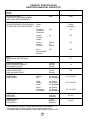
PRODUCT SPECIFICATION
ESPECIFICIONES DEL PRODUCTO
Model
Modèle
Modelo
HQ-2052UH
COOLING CAPACITY
CAPACITÉ DE REFROIDISSEMENT
CAPACIDAD DE ENFRIAMIENTO
ELECTRICAL RATING
CARACTÉRISTIQUES ÉLECTRIQUES
CLASIFICION DE LA ELECTRICIDAD
Btu/h
Phase
Phase
Fase
5,250
Single
Simple
Monofasico
Frequency
Fréquence
Frecuencia
(Hz)
60
Voltage
Tension
Voltaja
(V)
115
Current
Courant
Corriente
(Amps)
(A)
(Amps)
5.0
Input
Consommation
Potencia
(W)
540
EER
RENDEMENT ÉNERGÉTIQUE
EER
9.7
MOISTURE REMOVAL
SUPPRESSION D'HUMIDITÉ
DESHUMIDIFICACION
(Pints/h)
(pinte/h)
(Tinta/h)
1.4
ROOM CIRCULATION
CIRCULATION D'AIR
CIRCULACION DE AIRE
(Cf/min)
(pi/min)
(pie/min)
140
DIMENSIONS
DIMENSIONS
DIMENSIONES
Height
Hauteur
Alto
cm (inches)
cm (pouces)
cm (pulgadas)
31.2 (12 9/32")
Width
Largeur
Ancho
cm (inches)
cm (pouces)
cm (pulgadas)
47.2 (18 9/16")
Depth
Profondeur
Profundidad
cm (inches)
cm (pouces)
cm (pulgadas)
37.0 (14 9/16")
NET WEIGHT
POIDS NET
PESO NETO
kg (Ib)
kg (livres)
kb (libras)
20 (44)
GROSS WEIGHT
POIDS BRUT
PESO BRUTO
kg (Ib)
kg (livres)
kb (libras)
22 (48)
* Specification are subject to change without notice for improvement.
* Les spécifications ci-dessus peuvent être changées sans préavis.
* Las especificacionas están sujetas a cambios por majoras sin previo aviso.
25
Nota
26
Nota
27
Panasonic Consumer Electronics Company,
Division of Matsushita Electric Corporation
of America
One Panasonic Way
Secaucus, New Jersey 07094
Panasonic Sales Company,
Division of Matsushita Electric of Puerto Rico, Inc.,
Ave. 65 de Infanteria, Km. 9.5
San Gabriel Industrial Park
Carolina, Puerto Rico 00985
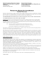
Panasonic Room Air Conditioner
Limited Warranty
Panasonic Consumer Electronics Company or Panasonic Sales Company (collectively referred to as "the Warrantor") will repair
this product with new or refurbished parts in case of defects in material or workmanship, free of charge, in the USA or Puerto
Rico in accordance to the following (All time periods start from the date of the original purchase).
SEALED REFRIGERATING SYSTEM (compressor and interconnecting tube): FIVE (5) YEARS - PARTS AND LABOR
ALL OTHER COMPONENTS: ONE (1) YEAR - PARTS AND LABOR
In-home service in the USA can be obtained during the warranty period by contacting a Panasonic Service Company (PASC)
Factory Servicenter listed in the Servicenter Directory. Or call toll free, 1-800-211-PANA(7262), to locate a PASC authorized
Servicenter. In-home service in Puerto Rico can be obtained during the warranty period by calling the Panasonic Sales Company
telephone number listed in the Servicenter Directory.
Note: If the unit is installed at the other than normal window height and/or has been
custom-installed (e.g., through the wall), the customer is responsible for removing
the unit from its installation prior to the performance of in-home service.
This warranty is extended only to the original purchaser. A purchase receipt or other proof of date of the original purchase is
required for service and parts replacement under this warranty.
This warranty only covers failures due to defects in materials and workmanship and does not cover normal wear or cosmetic
damage. The warranty does not cover damages which occur in shipment, or failures which are caused by products not supplied by
the warrantor, or failures which result from accident, misuse, abuse, neglect, mishandling, misapplication, faulty installation,
maladjustment of customer controls, improper maintenance, alteration, modification, power line surge, lightning damage,
improper voltage supply, commercial use such as hotel, office, restaurant, or other business or rental use of the product, or service
by anyone other than a PASC Factory Servicenter or a PASC authorized Servicenter, or damage that is attributable to acts of God.
LIMITS AND EXCLUSIONS
There are no express warranties except as listed above.
THE WARRANTOR SHALL NOT BE LIABLE FOR INCIDENTAL OR CONSEQUENTIAL DAMAGES RESULTING
FROM THE USE OF THIS PRODUCT, OR ARISING OUT OF ANY BREACH OF THIS WARRANTY ALL EXPRESS AND
IMPLIED WARRANTIES, INCLUDING THE WARRANTIES OF MERCHANTABILITY, ARE LIMITED TO THE
APPLICABLE WARRANTY PERIOD SET FORTH ABOVE.
Some states do not allow the exclusion or limitation of incidental or consequential damages or limitations on how long an
implied warranty lasts, so the above exclusions or limitations may not apply to you.
This warranty gives you specific legal rights and you may also have other rights which vary from state to state If a problem with
this product develops during or after the warranty period, you may contact your dealer or Servicenter If the problem is not
handled to your satisfaction, then write to the Consumer Affairs Department at the company address indicated above
SERVICE CALLS WHICH DO NOT INVOLVE DEFECTIVE MATERIALS OR WORKMANSHIP AS DETERMINED BY
THE WARRANTOR, IN ITS SOLE DISCRETION, ARE NOT COVERED COSTS OF SUCH SERVICE CALLS ARE THE
RESPONSIBILITY OF THE PURCHASER.
[For assistance, please call: 1-800-21 1-PANA (7262) or send e-mail to [email protected]]
Printed in Korea