1
KOBE Range Hoods
CHX30 Series (30” & 36”)
INSTALLATION INSTRUCTIONS
AND OPERATION MANUAL
MANUEL D'INSTALLATION
ET MODE D'EMPLOI
INSTRUCCIONES DE INSTALACIÓN
Y MANUAL DE OPERACIÓN
www.goedekers.com
[ENGLISH] ................................................................................................................................. 1
[FRENCH] .................................................................................................................................24
[SPANISH] ................................................................................................................................47
www.goedekers.com
[ENGLISH]
- READ AND SAVE THESE INSTRUCTIONS -
CONTENTS
IMPORTANT SAFETY INSTRUCTIONS .................................................................................... 2
COMPONENTS OF PACKAGE.................................................................................................. 4
INSTALLATION .......................................................................................................................... 5
OPERATION INSTRUCTIONS..................................................................................................10
MAINTENANCE ........................................................................................................................11
SPECIFICATIONS ....................................................................................................................12
MEASUREMENTS & DIAGRAMS.............................................................................................13
PARTS LIST..............................................................................................................................15
CIRCUIT DIAGRAM ..................................................................................................................18
TROUBLE SHOOTING .............................................................................................................19
DISCLAIMER ............................................................................................................................20
WARRANTY .............................................................................................................................21
PRODUCT REGISTRATION .....................................................................................................23
- READ ALL INSTRUCTIONS CAREFULLY BEFORE STARTING ALL WIRING MUST BE DONE BY A PROFESSIONAL AND IN
ACCORDANCE WITH NATIONAL AND LOCAL ELECTRICAL CODES
1
www.goedekers.com
IMPORTANT SAFETY INSTRUCTIONS
- PLEASE READ THIS SECTION CAREFULLY BEFORE INSTALLATION -
WARNING:
TO REDUCE THE RISK OF FIRE, ELECTRIC SHOCK OR PERSONAL
INJURY, OBSERVE THE FOLLOWING:
1) Installation and electrical wiring must be done by qualified professionals and in accordance with all
applicable codes and standards, including fire-rated construction.
2) When cutting or drilling into wall or ceiling, be careful not to damage electrical wiring or other hidden
utilities.
3) Ducted fans must be vented to the outside.
a) Before servicing or cleaning unit, open the light panel and SWITCH POWER OFF AT SERVICE
PANEL.
b) Clean all grease laden surfaces frequently. To reduce the risk of fire and to disperse air
properly, make sure to vent air outside. DO NOT vent exhaust air into wall spaces, attics, crawl
spaces or garages.
NOTE
-
This warranty is invalid without an authorized agent’s receipt or if unit is
damaged due to misuse, poor installation, improper use, mistreatment,
negligence or any other circumstances beyond the control of EPC
Trading Inc.
-
EPC Trading Inc. will not be held responsible for any damages to
personal property or real estate or any bodily injuries whether caused
directly or indirectly by the range hood.
WARNING:
•
•
•
•
•
•
•
•
TO REDUCE THE RISK OF PERSONAL INJURY IN THE EVENT OF A RANGE
TOP GREASE FIRE:
Keep all fan, baffle/spacer/filter/oil tunnel/oil container and grease-laden surfaces clean. Grease
should not be allowed to accumulate on fan, baffle/spacer/filter/oil tunnel/oil container.
Always turn hood ON when cooking.
Use high settings on cooking range ONLY when necessary.
Do not leave cooking range unattended when cooking.
Always use cookware and utensils appropriate for the type and amount of food prepared.
Use this unit only in the manner intended by the manufacturer.
Before servicing, switch power off at service panel and lock service panel (if possible) to prevent
power from switching on accidentally.
Clean ventilating fan frequently.
2
www.goedekers.com
What to Do In The Event Of a Range Top Grease Fire
•
•
•
•
SMOTHER FLAMES with a tight fitting lid, cookie sheet, or metal tray, and then turn off the burner.
KEEP FLAMMABLE OR COMBUSTIBLE MATERIAL AWAY FROM FLAMES. If the flames do not
go out immediately, EVACUATE THE AREA AND CALL THE FIRE DEPARTMENT or 911.
NEVER PICK UP A BURNING PAN – You May Get Burned.
DO NOT USE WATER, including wet dishcloths or towels – a violent steam blast will result.
Use an extinguisher ONLY if:
a) You have a Class A, B, C extinguisher and know how to operate it.
b) The fire is small and contained in the area where it started.
c) The fire department has been called.
d) You can fight the fire with your back to an exit.
What to Do If You Smell Gas
•
•
•
Extinguish any open flame.
Do not try to turn on the lights or any type of appliance.
Open all doors and windows to disperse the gas. If you still smell gas, call the Gas Company and
Fire Department right away.
CAUTION
1) For general ventilation use only. Do not use to exhaust hazardous or explosive materials and
vapors.
2) To reduce the risk of fire, use only metal ductwork. Sufficient air is needed for proper combustion
and exhausting of gases through the flue (chimney) to prevent back drafting.
3) Follow the heating equipment manufacturer’s guideline and safety standards such as those
published by the National Fire Protection Association (NFPA), and the American Society for
Heating, Refrigeration and Air Conditioning Engineers (ASHRAE), and code authorities.
4) Activating any switch on may cause ignition or an explosion.
5) Due to the size and weight of this hood, two people installation is recommended.
ELECTRICAL SHOCK HAZARD – Can result in serious injury or death.
Disconnect appliance from electric power before servicing. If equipped, the
fluorescent light bulb contains small amounts of mercury, which must be
recycled or disposed of according to Local, State, and Federal Codes.
3
www.goedekers.com
COMPONENTS OF PACKAGE
(Must keep all material for returns or refunds)
Range Hood Box
{A}
{B}
{C}
{D}
{E}
{F}
{G}
Brillia Range Hood – 1
Warranty Registration Card – 1
Instruction Manual – 1
Round Exhaust Plate with damper – 1
Rectangular Exhaust Plate with damper – 1
Light bulb – 2
Parametric Panel – 1
{A}
{C}
{F}
-
{B}
{D}
{E}
{G}
FOR MORE INFORMATION, PLEASE CONTACT BRILLIA BY KOBE AT (626) 775-6388.
4
www.goedekers.com
INSTALLATION
PLEASE READ ENTIRE INSTRUCTIONS BEFORE PROCEEDING
Calculation before Installation
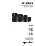
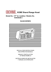
To calculate installation, please refer to TABLE 1. (All calculation in inches.)
- FOR UNDER THE CABINET TABLE 1
A = Height of Floor to Ceiling
B = Height of Floor to Counter Top
(Standard: 36”)
C = Preferred Height of Counter Top to Hood
Bottom (Recommended 27” to 30”)
D = Height of Hood
E = Height of the Cabinet
SAFETY WARNING
HOOD MAY HAVE VERY SHARP EDGES; PLEASE WEAR PROTECTIVE GLOVES IF
REMOVING ANY PARTS FOR INSTALLING, CLEANING OR SERVICING.
NOTE: BE CAREFUL WHEN USING ELECTRICAL SCREWDRIVER, DAMAGE TO THE HOOD
MAY OCCUR.
5
www.goedekers.com
Figure 1
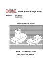
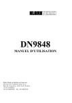
Preparation before Installation
NOTE: TO AVOID DAMAGE TO YOUR HOOD,
PREVENT
DEBRIS
FROM
ENTERING THE VENT OPENING.
•
•
•
•
•
•
•
•
Decide the location of the venting pipe
from the hood to the outside. Refer to
Figure 1.
A straight, short venting run will allow
the hood to perform more efficiently.
Try to avoid as many transitions,
elbows, and long run as possible. This
may reduce the performance of the
hood.
Temporarily wire the hood to test for
proper operation before installing.
Important: Peel protective film off
the hood (if any).
For installing under the cabinet with
recessed bottom, attach 4-inch wide
wood filler strips (not included) on each
side. Refer to Figure 2.
Using reference on Page 13 and 14 to
measure and create access opening for
electrical wires and exhaust under the
cabinet {refer to Vent Option Installation
on 7}. Refer to Figure 3.
Using reference on Page 13 and 14 to
position the mounting screws (not
included) underneath the cabinet. Refer
to Figure 4.
Figure 2
Figure 3
Install Lights before mounting hood
Figure 4
To install the light fixture:
- Insert the light fixture into the socket
and turn it clockwise to secure the
light fixture.
6
www.goedekers.com
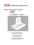
Figure 7
Vent option installation
1. Choose the require vent option.
NOTE: If the hood is to be installed as
ductless application, please do not remove
any duct knockout located at the top or the
back of the hood.
2. For 7” Round vent installation only:
- Using a flat-head screwdriver to remove
the 7” duct knockout. (Refer to Figure 5)
- Attached the 7” exhaust plate using 8
screws (provided). Refer to Figure 6.
3. For 3-1/4” x 10” vent installation only:
- Using a flat-head screwdriver to remove
the top OR the rear 3-1/4” x 10” duct
knockout. (Refer to Figure 7)
- Attached the 3-1/4” x 10” exhaust plate
using 6 screws (provided). Refer to
Figure 8 for Top Vent OR Figure 9 for
Rear Vent.
4. For ductless installation only.
- Remove the recirculating plate located
at the top of the hood, refer to Figure 10.
- Reinstall
the
recirculating
plate
horizontally as shown in Figure 11.
Figure 8
Figure 9
Figure 5
Figure 10
Figure 6
Figure 11
7
www.goedekers.com
Figure 12
Wiring to Power Supply
SAFETY WARNING
RISK OF ELECTRICAL SHOCK.
THIS
RANGE HOOD MUST BE PROPERLY
GROUNDED. MAKE SURE THIS IS DONE
BY
SPECIALIZED
ELECTRICIAN
IN
ACCORDANCE WITH ALL APPLICABLE
NATIONAL AND LOCAL ELECTRICAL
CODES.
BEFORE CONNECTING WIRES,
SWITCH POWER OFF AT SERVICE PANEL
AND LOCK SERVICE PANEL TO PREVENT
POWER FROM BEING SWITCHED ON
ACCIDENTALLY.
5. Connect the electrical wires.
- Connect three wires (black, white and
green) to house wires and cap with wire
connectors. Connect according to color:
black to black, white to white, and green
to green.
Figure 13
Hood Installation
CAUTION: If required to move the
cooking
range
to
install
the
hood, turn off the power on an electric range
at the main electrical box.
SHUT OFF
THE
GAS
BEFORE
MOVING
A
GAS RANGE.
6. Align screws with the mounting holes on top
of the range hood, and push toward the wall
to secure the unit in place. Refer to Figure
12 and Figure 13.
8
www.goedekers.com
Figure 14
Final Assembly
7. To install the parametric panel:
- Align the parametric panel at the
back of the unit. Refer to Figure 14.
- Push the unit upward, and slide the
parametric panel forward into the
notch to secure the panel. Refer to
Figure 15.
- Flip the parametric panel upward
until it clicks into place. Refer to
Figure 16.
CAUTION: MAKE SURE THE PARAMETRIC
PANEL IS SECURE BEFORE RELEASING.
Figure 15
8. Turn power ON in control panel. Check all
light and fan operation.
9. Make sure to leave this manual for the
homeowner.
Figure 16
9
www.goedekers.com
OPERATION INSTRUCTIONS
For models equipped with Push Button:
To operate the fan function
•
Press button to choose from speed.
o 1 = Low speed
o 2 = Medium speed
o 3 = High speed
• Press “0” to turn fan off.
To operate the light function
• Press the Light Control to turn lights on and off.
For models equipped with Rotary Switch:
To operate the fan function
• Turn the Speed Control clockwise to choose
speed.
• Turn the Speed Control counterclockwise to
“OFF”.
To operate the light function
• Turn the Light Control clockwise to turn on the
light.
• Turn the Light Control counterclockwise to
“OFF”.
For models equipped with Slide Switch:
To operate the fan function
• Slide the Speed Controls to choose speed.
o 1 = Low speed
o 2 = Medium speed
o 3 = High speed
To operate the light function
•
10
Slide the Light Control to turn lights on and off.
www.goedekers.com
MAINTENANCE
SAFETY WARNING
NEVER PUT YOUR HAND INTO AREA HOUSING THE FAN WHILE THE FAN IS OPERATING.
Cleaning Hood Surface
CAUTION:
NEVER USE ABRASIVE CLEANERS, PADS, OR CLOTHS. DO NOT USE
PAPER TOWEL ON STAINLESS STEEL.
For optimal operation, clean range hood and all baffle/spacer/filter/oil tunnel/oil container regularly.
*** Regular care will help preserve the appearance of the hood.
1. Use only mild soap or detergent solutions. Dry surfaces using soft cloth.
2. If hood looks splotchy (stainless steel hood), use a stainless steel cleaner to clean the surface
of the hood. Avoid getting cleaning solution onto or into the control panel. Follow directions of
the stainless steel cleaner. Caution: Do not leave on too long as this may cause damage to
hood finish. Use soft towel to wipe off the cleaning solution, gently rub off any stubborn spots.
Use dry soft towel to dry the hood.
3. DO NOT allow deposits to accumulate or remain on the hood.
4. DO NOT use ordinary steel wool or steel brushes. Small bits of steel may adhere to the surface
and cause rusting.
5. DO NOT allow salt solutions, disinfectants, bleaches, or cleaning compounds to remain in
contact with stainless steel for extended periods. Many of these compounds contain chemicals,
which may be harmful. Rinse with water after exposure and wipe dry with a clean lint free cloth.
To Clean Filter
CAUTION: CLEAN FILTER AND PARAMETRIC PANEL PERIODICALLY.
1. Remove parametric panel and aluminum filters.
2. Using a sponge, wash with warm soapy water. Dry completely before returning into place.
NOTE: MAKE SURE THE PARAMETRIC PANEL IS SECURE BEFORE RELEASING.
11
www.goedekers.com
SPECIFICATIONS
Series
CHX30 Series
CONSUMPTION / AMPERE
0.88 Ampere
VOLTAGE
120V 60Hz
NUMBER OF MOTORS
1
DESIGN
20-Gauge Seamless / Satin Finish
with
Glass Parametric panel or Stainless Steel Parametric panel
EXHAUST
Top 7” Round with damper
Top 3-1/4” x 10” Rectangular with damper
Rear 3-1/4” x 10” Rectangular with damper
CONTROLS
Push Button control system
OR
Rotary control system
OR
Slide control system
LIGHTS
7-watt CFL light x 2
HOOD DIMENSION
(W x D x H)
30” models – 29-3/4” x 21” x 6”
36” models – 35-3/4” x 21” x 6”
WEIGHT (lbs)
30”
36”
SPEED
Air Capacity (cfm)
Sone
CFL Series
290
4.0
Net
35
40
Specifications information is subject to change without notice.
12
www.goedekers.com
Gross
42
44
MEASUREMENTS & DIAGRAMS
All measurements in ( ) are millimeters.
All inch measurements are converted from millimeters. Inch measurements are estimated.
- FOR TOP VENTING -
- FOR REAR VENTING -
13
www.goedekers.com
- DIMENSIONS OF THE MODEL-
14
www.goedekers.com
PARTS LIST
For models equipped with Push Button:
HOOD
NO.
1
DESCRIPTION
Motor Mounting Plate
2
Hood Frame
3
4
5
6
Recirculating Box
Light socket
Push Button Control
Light Support
7
Light / Control Panel
8
Light fixture
9
Motor
10
Turbine Impeller
11
Bottom Casing
12
13
14
15
16
Parametric Panel support clip (Left)
Safety Screen
Magnetic Mechanism
Parametric Panel support clip (Right)
Aluminum Filter
17
Parametric Panel
18
Recirculating Panel
MODEL /SIZE
CHX3030PD (30”)
CHX3036PD (36”)
CHX3030PD (30”)
CHX3036PD (36”)
For CFL lighting system
CHX3030PD (30”)
CHX3036PD (36”)
Glass Parametric Panel (30”)
Glass Parametric Panel (36”)
Stainless Steel Parametric Panel (30”)
Stainless Steel Parametric Panel (36”)
15
www.goedekers.com
PART NO.
Y21-2355-P
Y20-1248-Q
Y20-1219-Q
Y36-0228
GF F005-00000
Y50-0087
Y20-1273-P
Y20-1278-Q
Y20-1276-Q
Y53-0441
Y54-0005
Y54-0005-1
Y23-0049
Y21-2743-6
Y21-2693-6
Y23-0041
Y36-0227
Y23-0040
Y23-0042
Y23-0043
PPG30
PPG36
PPS30
PPS36
Y21-2732-P
For models equipped with Rotary Switch:
HOOD
NO.
1
DESCRIPTION
Motor Mounting Plate
2
Hood Frame
3
4
5
6
7
Recirculating Box
Light socket
Speed Control
Light Control
Light Support
8
Light / Control Panel
9
10
Light fixture
Rotary Knobs
11
Motor
12
Turbine Impeller
13
Bottom Casing
14
15
16
17
18
Parametric Panel support clip (Left)
Safety Screen
Magnetic Mechanism
Parametric Panel support clip (Right)
Aluminum Filter
19
Parametric Panel
20
Recirculating Panel
MODEL /SIZE
CHX3030RD (30”)
CHX3036RD (36”)
CHX3030RD (30”)
CHX3036RD (36”)
For CFL lighting system
CHX3030RD (30”)
CHX3036RD (36”)
Glass Parametric Panel (30”)
Glass Parametric Panel (36”)
Stainless Steel Parametric Panel (30”)
Stainless Steel Parametric Panel (36”)
16
www.goedekers.com
PART NO.
Y21-2355-P
Y20-1248-Q
Y20-1219-Q
Y36-0228
GF F005-00000
Y50-0085
Y50-0084
Y20-1273-P
Y20-1249-P
Y20-1220-P
Y53-0441
Y32-0445
Y54-0005
Y54-0005-1
Y23-0049
Y21-2743-6
Y21-2693-6
Y23-0041
Y36-0227
Y23-0040
Y23-0042
Y23-0043
PPG30
PPG36
PPS30
PPS36
Y21-2732-P
For models equipped with Slide Switch:
HOOD
NO.
1
DESCRIPTION
Motor Mounting Plate
2
Hood Frame
3
4
5
Recirculating Box
Light socket
Light Support
6
Light / Control Panel
7
8
Light fixture
Slide Switch
9
Motor
10
Turbine Impeller
11
Bottom Casing
12
13
14
15
16
Parametric Panel support clip (Left)
Safety Screen
Magnetic Mechanism
Parametric Panel support clip (Right)
Aluminum Filter
17
Parametric Panel
18
Recirculating Panel
MODEL /SIZE
CHX3030SD (30”)
CHX3036SD (36”)
CHX3030SD (30”)
CHX3036SD (36”)
For CFL lighting system
CHX3030SD (30”)
CHX3036SD (36”)
Glass Parametric Panel (30”)
Glass Parametric Panel (36”)
Stainless Steel Parametric Panel (30”)
Stainless Steel Parametric Panel (36”)
17
www.goedekers.com
PART NO.
Y21-2355-P
Y20-1248-Q
Y20-1219-Q
Y36-0228
GF F005-00000
Y20-1273-P
Y20-1296-Q
Y20-1297-Q
Y53-0441
Y50-0088
Y54-0005
Y54-0005-1
Y23-0049
Y21-2743-6
Y21-2693-6
Y23-0041
Y36-0227
Y23-0040
Y23-0042
Y23-0043
PPG30
PPG36
PPS30
PPS36
Y21-2732-P
CIRCUIT DIAGRAM
For models equipped with Push Control:
For models equipped with Rotary Switch:
For models equipped with Slide Switch:
18
www.goedekers.com
TROUBLE SHOOTING
Issue
After Installation,
both motors and
lights are not
working.
Lights are
working, but
motor is not.
The range hood
is vibrating.
Possible Cause
The power is not on.
Solution
Make sure the circuit breaker and the unit’s power is
ON. Use a voltage meter to check the power supply.
Check and tighten wire connection.
Replace the control panel.
Replace the motor.
Replace capacitor.
Replace the control panel or processing board.
The wire connection is not secure.
The control panel is defective.
The motor is defective.
The capacitor is defective.
The control panel is defective.
The blower system is not secure.
The turbine impeller/squirrel cage is not
balanced.
Hood is not secured in place.
The motor is
working, but the
lights are not
working.
Light bulb(s) is defective.
The light wiring(s) is loose.
The control panel is defective.
The range hood
is not venting
out correctly.
Cold air is
coming into the
home.
The range hood is installed outside of the
manufacturer recommended clearance.
There is no make-up air inside the house.
Tighten the turbine impeller/squirrel cage and air
chamber.
Replace the turbine impeller/squirrel cage.
Check the installation of hood, tighten the mounting
bracket.
Try placing the trouble light bulb(s) to a working
socket, if the bulb(s) still doesn’t work; replace the
halogen light bulb(s).
Check wire continuity from control panel to light
housing(s).
Replace the control panel.
Obstacle blocking the pipe work.
Adjust the clearance, the distance between the range
hoods and cook top, from 27” to 30”.
Open the window to enhance the performance of the
range hood by creating sufficient make-up air.
Remove all obstacles from the duct work.
The pipe size is smaller than the
suggested pipe size.
The pipe connection is not properly sealed.
Change the ducting according to the manufacturer
suggestion.
Check the pipe installation.
19
www.goedekers.com
DISCLAIMER
1. CAREFULLY INSPECT ALL ITEMS FOR DAMAGES BEFORE ACCEPTING DELIVERY. NOTE
ANY DAMAGES ON THE FREIGHT BILL OR EXPRESS RECEIPT. REQUEST NAME AND
SIGNATURE OF THE CARRIER’S AGENT AND KEEP COPY TO SUPPORT YOUR CLAIM.
Upon acceptance of items, owner assumes responsibility for its safe arrival. Report damages to the
carrier and file a claim immediately. Failure to do so may result in the denial of your claim. The
carrier will furnish you with necessary forms for filing a claim.
DAMAGES CAUSED DURING TRANSIT ARE NOT COVERED UNDER OUR WARRANTY.
2. PLEASE INSPECT CONTENTS OF PACKAGE(S) CAREFULLY UPON RECEIVING!
We must be notified in writing of any damages and/or missing parts within the allocated days upon
your receipt of package(s).
CLAIMS WILL NOT BE ACCEPTED AFTER THE ALLOCATED DAYS.
NOTE: ITEMS WERE THOROUGHLY TESTED AND CAREFULLY PACKED IN OUR FACTORY
BEFORE SHIPPING.
3. Products must be returned in good working condition with ALL original parts and documentation
packed in ALL original cartons, fillers and shipping cartons.
EXCHANGES OR RETURNS MAY NOT BE ACCEPTED IF ANY PACKAGING IS MISSING.
4. MAKE SURE TO INSPECT THE HOOD FOR DAMAGES AND DEFECTS BEFORE
INSTALLATION. Appearance flaws of the hood found after installation and not affecting hood
performance is not covered under our warranty for returns or exchanges.
A)
Before Installation: Return for exchange or refund (please see above for acceptable
returns).
B)
After Installation:
NO exchange or refund.
20
www.goedekers.com
WARRANTY
WARRANTY CERTIFICATE
EPC Trading Inc. warrants all products manufactured or supplied by it to be free from defects in
workmanship and materials. Its obligations pursuant to this warranty are limited to a period of one year
from the date of purchase and to the replacement at its option and subject to the terms and conditions
stated below, of any component part, which its examination shall disclose to be so defective.
ONE-YEAR PART WARRANTY
Any covered failure occurring within one year of original purchase arising from defective workmanship
or material in manufacture will be, at our discretion, replaced free of charge by EPC Trading Inc. as
applicable. Keep proof of purchase (or original invoice) handy for inspection.
If the range hood is sold by the original purchaser during the warranty period the new owner is
protected until expiration of the original purchaser’s warranty.
CONDITIONS
The following conditions apply only in relation to the warranty expressly given in this certificate.
1) This warranty applies only:
a) within U.S.A. and Canada.
b) to range hoods used for PRIVATE SINGLE FAMILY USE (if used for COMMERCIAL or
MULTIPLE FAMILY USE or other purposes, warranty will be voided).
2) Repair of any fault to be provided under this warranty shall not be provided:
a) if the identification number attached to the range hood has been altered, rendered illegible or
removed;
b) if notice of the defect has not been given within the period applicable;
c) for failure of light bulbs or heat lamps;
d) for physical damage;
e) for surfaces damaged by use of improper chemical cleaning agents;
f) if the appliance has been:
i) subject to misuse, abuse, negligence, accident, incorrect installation or failure to follow the
operating instructions;
ii) connected to improper, inadequate or faulty electricity service or exhaust ducts, flues or duct
cover, or operated using incorrect or contaminated lubricants;
g) for damage to range hood during transit, delivery, installation or removal;
h) noise or vibration caused by improper installation of range hood and/or damper.
3) The purchaser must produce proof of purchase together with this warranty certificate when making
the claim.
4) Damages caused during shipment are not covered under our warranty.
21
www.goedekers.com
CONSEQUENTIAL DAMAGE
The warrantor is not responsible for any consequential damage. SOME STATES DO NOT ALLOW
THE EXCLUSION OF CONSEQUENTIAL DAMAGE SO THE ABOVE EXCLUSION MAY NOT APPLY
TO YOU.
IMPLIED WARRANTIES/STATE LAW
Any implied warranties, including the implied warranty of merchantability and fitness for purpose,
imposed on the sale by the laws of the state of sale are limited to one year from the date of original
purchase. Some states do not allow limitations on the duration of implied warranties. This warranty
gives you specific legal rights, and may also have rights, which vary from state to state.
CUSTOMER SERVICE
For service contact:
KOBE Range Hoods
11775 Clark Street
Arcadia, CA 91006
U.S.A.
Tel: (626) 775-8880
Email: [email protected]
Website: www.KOBERangeHoods.com
22
www.goedekers.com
PRODUCT REGISTRATION
Register Your Product!
Any covered failure occurring within two years of original purchase arising from defective
workmanship or material in manufacture will be repaired or at our option the unit will be replaced
free of charge by EPC Trading Inc. as applicable. Keep proof of purchase (original invoice)
handy for inspection.
If the range hood is sold by the original purchaser during the warranty period the new owner
is protected until expiration of the original purchaser’s warranty. See warranty section for
complete warranty coverage information.
This appliance has been manufactured, tested, and inspected to the standards required by EPC
Trading Inc.
PLEASE MAIL IN YOUR WARRANTY REGISTRATION CARD AND PROOF OF
PURCHASE TO:
KOBE Range Hoods
Warranty Registration
11775 Clark Street
Arcadia, CA 91006
U.S.A.
RECORD THE FOLLOWING INFORMATION FOR YOUR RECORD:
Model No.____________________________________________________
Serial No. ____________________________________________________
Purchased Date
_____ / ______ /
Purchased From:
_____________________________
_____________________________
_____________________________
IMPORTANT:
PLEASE KEEP A COPY OF YOUR SALE RECEIPT OR INVOICE HANDY WHEN
REQUESTING SERVICE.
23
www.goedekers.com
[FRENCH]
- LIRE ET CONSERVER CES INSTRUCTIONS -
TABLE DES MATIÈRES
CONSIGNES DE SÉCURITÉ IMPORTANTES .................................................................................... 25
CONTENU DE L’EMBALLAGE ............................................................................................................ 27
INSTALLATION ................................................................................................................................... 28
MODE D'EMPLOI ................................................................................................................................ 33
ENTRETIEN PRÉVENTIF ................................................................................................................... 34
SPÉCIFICATIONS ............................................................................................................................... 35
MESURES ET SCHÉMAS ................................................................................................................... 36
LISTE DES PIÈCES ............................................................................................................................ 38
SCHÉMA DE CÂBLAGE ...................................................................................................................... 41
TROUBLE SHOOTING ........................................................................................................................ 42
AVIS DE NON-RESPONSABILITÉ ...................................................................................................... 43
GARANTIE .......................................................................................................................................... 44
ENREGISTREMENT DU PRODUIT .................................................................................................... 46
LIRE ATTENTIVEMENT TOUTES LES CONSIGNES AVANT DE COMMENCER
TOUT LE CÂBLAGE ÉLECTRIQUE DOIT ÊTRE EFFECTUÉ
PAR UN PROFESSIONNEL EN CONFORMITÉ AVEC LES CODES D'ÉLECTRICITÉ LOCAUX ET
NATIONAUX
24
www.goedekers.com
CONSIGNES DE SÉCURITÉ IMPORTANTES
- SVP LIRE CETTE SECTION ATTENTIVEMENT AVANT L'INSTALLATION -
AVERTISSEMENT:
1)
2)
3)
L'installation et le câblage électrique doivent être effectués par des techniciens qualifiés et en
conformité avec tous les codes et toutes les normes qui s'appliquent même pour les constructions
ignifugées.
Lorsque vous découpez ou percez un mur ou un plafond, prendre soin de ne pas endommager le
filage électrique ou autres conduits cachés.
Les hottes à évacuation doivent être évacuées à l'extérieur.
a) Avant une réparation, un entretien préventif ou un nettoyage, ouvrir le panneau de la lumière
et COUPER LE COURANT ÉLECTRIQUE SUR LE TABLEAU DE DISTRIBUTION.
b) Nettoyer le ventilateur, le filtre optionnel et les surfaces chargées de graisse fréquemment.
Afin de réduire les risques d'incendie et afin de disperser l'air adéquatement, évacuer l'air à
l'extérieur. NE PAS ventiler l'air d'évacuation dans les murs, les greniers, les vides sanitaires
ou les garages.
NOTE
-
La garantie de cet appareil sera nulle sans le reçu d'un distributeur
autorisé de KOBE ou si l'appareil est endommagé par une utilisation
inadéquate, une installation déficiente, un usage inapproprié, un
mauvais traitement, de la négligence ou par toute autre circonstance
échappant au contrôle des distributeurs autorisés de EPC Trading Inc..
-
EPC Trading Inc. se dégage de toute responsabilité face à des
dommages à la propriété personnelle ou aux biens immeubles ou
encore à des blessures corporelles causées directement ou
indirectement par la hotte de cuisinière.
AVERTISSEMENT
•
•
•
•
•
•
•
•
AFIN DE RÉDUIRE LES RISQUES D'INCENDIE, DE CHOC
ÉLECTRIQUE ET DE BLESSURES, RESPECTER LES CONSIGNES
SUIVANTES :
: AFIN DE RÉDUIRE LES RISQUES DE BLESSURES
CORPORELLES DANS L'ÉVENTUALITÉ D'UN INCENDIE DE
GRAISSE SE DÉCLARANT SOUS LA HOTTE DE CUISINIÈRE :
Tenir toujours propres le ventilateur, les filtres déflecteurs, s'il y en a, et les surfaces chargées de
graisse.
Toujours faire fonctionner la hotte lors d'une cuisson à température élevée.
Utiliser les vitesses élevées de la hotte UNIQUEMENT lorsque nécessaire. Chauffer l'huile
lentement aux réglages de basses ou de moyennes vitesses.
Ne pas laisser la cuisinière sans surveillance lors de la cuisson.
Toujours utiliser les articles de cuisson et les ustensiles appropriés au type et à la quantité
d'aliments préparés.
Utiliser l'appareil seulement pour l'usage auquel le fabricant l'a destiné.
Avant l'entretien courant, couper l'alimentation électrique au tableau de distribution principal et
verrouiller ce dernier (si possible) pour éviter une mise en marche accidentelle.
Nettoyer les ventilateurs fréquemment.
25
www.goedekers.com
Que faire en cas d'un incendie de graisse sur la cuisinière
•
•
•
•
ÉTOUFFER LES FLAMMES à l'aide d'un couvercle hermétique, une plaque à biscuits ou un
plateau métallique, puis fermer le rond ou le brûleur. GARDER LES MATÉRIAUX INFLAMMABLES
OU COMBUSTIBLES LOIN DES FLAMMES. Si les flammes ne s'éteignent pas immédiatement,
ÉVACUER LA ZONE ET APPELER LE SERVICE D'INCENDIE ou le 911.
NE JAMAIS SOULEVER UNE CASSEROLE EN FEU - Il y a risque de brûlure.
NE PAS UTILISER D'EAU incluant serviettes ou linges à vaisselle mouillés - cela provoquerait un
violent jet de vapeur.
Utiliser un extincteur SEULEMENT si:
a)
vous possédez un extincteur de classe A, B ou C et si vous savez vous en servir ;
b)
le feu est petit et est contenu dans la zone de départ ;
c)
vous avez appelé le service d’incendie ;
d)
vous pouvez combattre le feu le dos près d'une sortie.
Que faire si une odeur de gaz se dégage
•
•
•
Éteindre toute flamme nue.
Ne pas essayer d'allumer des lumières ou tout type d'appareil électroménager.
Ouvrir toutes les portes et fenêtres afin de chasser le gaz. Si une odeur de gaz est toujours
perceptible, appeler votre fournisseur de gaz ainsi que le service d'incendie immédiatement.
ATTENTION !
1) Cette hotte doit être utilisée uniquement pour une ventilation normale. Ne pas s'en servir pour
évacuer des substances et vapeurs dangereuses ou explosives.
2) Afin de réduire les risques d'incendie, employer seulement des conduits de métal. Il doit y avoir
suffisamment d’air pour une combustion et une évacuation des gaz appropriées par le conduit de
fumée (cheminée) afin d’éviter le refoulement d’air.
3) Suivre les directives et les consignes de sécurité des fabricants d'équipement de chauffage comme
celles publiées par le National Fire Protection Association
(NFPA) et l'American Society for
Heating, Refrigeration and Air Conditioning Engineers (ASHRAE) de même que les codes en
vigueur.
4) L’activation de tout interrupteur peut provoquer l’allumage ou une explosion.
5) En raison de la taille et du poids de la hotte, il est recommandé que deux personnes participent à
l’installation.
RISQUE DE CHOC ÉLECTRIQUE - Pouvant entraîner la mort ou des
blessures graves. Couper l'alimentation électrique à l'appareil avant tout
entretien ou toute réparation. Si la hotte est munie d'une ampoule
fluorescente, cette dernière contient une petite quantité de mercure et, en
conséquence, elle doit être recyclée ou éliminée conformément aux codes
locaux, provinciaux et fédéraux qui s'appliquent
26
www.goedekers.com
CONTENU DE L’EMBALLAGE
(Pour tout retour ou remboursement conserver le matériel ainsi que l’emballage
d’origine)
Boîte de la hotte de cuisinière Hotte de cuisinière
{A}
{B}
{C}
{D}
{E}
{F}
{G}
Hotte Brillia – 1
Certificat de garantie – 1
Notice d'installation et mode d'emploi – 1
Plaque Ronde Plastique – 1
Plaque Rectangulaire Plastique – 1
Lampe – 2
Panneau Paramétrique – 1
{A}
{C}
{F}
•
{B}
{D}
{E}
{G}
POUR PLUS D’INFORMATIONS, VEUILLEZ COMMUNIQUER AVEC Brillia by KOBE AU (626) 775-6388.
27
www.goedekers.com
INSTALLATION
SVP LIRE LE MANUEL D’INSTRUCTION AU COMPLET AVANT L'INSTALLATION
Mesures à prendre avant l'installation
Calculer la longueur de l'installation avant d'installer la hotte. (Toutes les mesures sont données en
pouces).
- HOTTE INSTALLÉE SOUS UNE ARMOIRE TABLEAU 1
A = Hauteur du plancher au plafond
B = hauteur du plancher jusqu’au comptoir/
à la surface de cuisson
(Normalement : 36 ")
C = hauteur recommandée entre le dessus du
comptoir/surface de cuisson jusqu’au
dessous de la hotte
(Recommandation : 27"à 30")
D = Hauteur de la hotte
E = Hauteur du cabinet d’armoire
CONSIGNES DE SÉCURITÉ
LES HOTTES PEUVENT AVOIR DES BORDS TRÈS TRANCHANTS ; PORTER DES GANTS DE
PROTECTION SI NÉCESSAIRE POUR RETIRER DES PIÈCES LORS DE L'INSTALLATION, DU
NETTOYAGE, DE L'ENTRETIEN ET DES RÉPARATIONS.
NOTE: FAIRE PREUVE DE PRÉCAUTION EN UTILISANT UN TOURNEVIS ÉLECTRIQUE PUISQUE
CE DERNIER RISQUE D'ENDOMMAGER LA HOTTE.
28
www.goedekers.com
Photo 1
PRÉPARATION AVANT L'INSTALLATION
NOTE: AFIN
DE
PRÉVENIR
TOUT
DOMMAGE À LA HOTTE, IL FAUT
EMPÊCHER LES DÉBRIS DE
PÉNÉTRER DANS L'OUVERTURE
DE VENTILATION.
•
•
•
•
•
•
•
•
Choisir l'emplacement du conduit de
ventilation de la hotte vers l'extérieur.
Voir Photo 1.
Un conduit court et droit permet de
maximiser le rendement de la hotte.
Essayer d'éviter autant que possible les
raccords, les coudes et les longues
sections de conduit puisque ceux-ci
peuvent réduire le rendement de la
hotte.
Avant de l'installer, brancher la hotte
temporairement pour vérifier si son
fonctionnement est adéquat.
Important : enlever la pellicule
protectrice de la hotte (s'il y a lieu).
Si le fond de l'armoire est en retrait, fixer
un morceau de bois de 4 po de largeur
(non inclus) de chaque côté. Voir Photo
2.
À l'aide des références des mesures de
la page 36 et 37, mesurer et découper
un orifice sous l'armoire pour y passer le
filage électrique et l'évent de en
plastique.
{Voir
L'OPTION
D'INSTALLATION DE VENTILATION}.
À l'aide des références des mesures de
la page 36 et 37, à la position des vis de
montage (non inclus) sous l'armoire.
Voir Photo 4.
Photo 2
Photo 3
Photo 4
INSTALLER LA LAMPE AVANT L'INSTALLATION
Pour installer la lumière:
- Insérer la lampe dans la douille et
aiguilles d'une montre pour fixer la
lumière
29
www.goedekers.com
Photo 7
L'OPTION D'INSTALLATION DE
VENTILATION
1. Choisir le besoin de ventilation option.
NOTE: Si la hotte doit être installé comme
application de recirculation, s'il vous plaît ne
pas supprimer les knockout conduit situé en
haut ou l'arrière de la hotte.
2. Pour 7 po conduit rond installation :
- En utilisant un tournevis à tête plate
pour retirer le de 7 po trou
d'échappement. (Voir Photo 5)
- Installer la plaque en plastique à l'aide
de 8 vis (inclus). Voir Photo 6.
3. Pour 3-1/4 po x 10 po conduit rectangulaire
installation :
- En utilisant un tournevis à tête plate
pour retirer le sur le dessus ou l'arrière
le de 3-1/4 po x 10 po trou
d'échappement. (Voir Photo 7)
- Installer la plaque en plastique à l'aide
de 6 vis (inclus). Voir Photo 8 par
ventilation sur le dessus. Ou voir Photo
9 par ventilation a l’arrière.
4. Pour installer comme application de
recirculation.
- Retirer la plaque située au sur le dessus
de la hotte. Voir Photo 10.
- Réinstaller la plaque horizontale comme
le montre la photo 11.
Photo 8
Photo 9
Photo 5
Photo 10
Photo 6
Photo 11
30
www.goedekers.com
Photo 12
RACCORDEMENT AU RÉSEAU DE CONDUITS
CONSIGNES DE SÉCURITÉ
RISQUE DE CHOC ÉLECTRIQUE. CETTE
HOTTE DE CUISINIÈRE DOIT ÊTRE MISE À
LA TERRE ADÉQUATEMENT. CE TRAVAIL
DOIT
ÊTRE
EXÉCUTÉ
PAR
UN
ÉLECTRICIEN
PROFESSIONNEL
EN
CONFORMITÉ AVEC TOUS LES CODES
D'ÉLECTRICITÉ LOCAUX ET NATIONAUX
QUI S'APPLIQUENT. AVANT DE BRANCHER
DES
FILS,
COUPER
LE
COURANT
ÉLECTRIQUE
AU
TABLEAU
DE
DISTRIBUTION
PRINCIPAL
ET
VERROUILLER CE DERNIER POUR ÉVITER
QUE
LE
COURANT
SOIT
REMIS
ACCIDENTELLEMENT.
5. Branchement des fils électriques.
- Raccorder les trois fils (noir, blanc et
vert) aux fils de la maison et les couvrir
avec des capuchons de connexion.
Raccorder les fils selon la couleur : noir
avec noir, blanc avec blanc et vert avec
vert.
INSTALLATION DE
Photo 13
LA HOTTE
AVERTISSEMENT : S'il faut déplacer
une cuisinière électrique pour installer la
hotte,
couper
d'abord
l'alimentation
électrique à cette cuisinière par le tableau
de distribution principal. COUPER LE GAZ
AVANT DE DÉPLACER UNE CUISINIÈRE À
GAZ.
6. Aligner les vis avec les trous de montage
sur le dessus de la hotte et pousser vers le
mur pour fixer la hotte. Voir Photo 12 et 13.
31
www.goedekers.com
ASSEMBLAGE FINAL
Photo 14
7. Pour installer le panneau paramétrique
- Aligner le panneau paramétrique à
l'arrière de la hotte. Voir Photo 14.
- Poussez le panneau vers le haut et
faites glisser le panneau avant dans
l'encoche et fixer le panneau. Voir
Photo 15.
- pousser le panneau vers le haut
jusqu'à ce qu'il se verrouille en
place. Voir Photo 16.
Photo 15
AVERTISSEMENT : S'ASSURER QUE LA
HOTTE ET LE PANNEAU PARAMETRIQUE
EST BIEN FIXÉE AVANT DE LA LÂCHER.
8. Démarrer
la hotte par la commande
marche/arrêt
(ON/OFF).
Vérifier
le
fonctionnement de toutes les lampes et du
ventilateur.
9. Remettre ce manuel au propriétaire pour
consultation future.
Photo 16
32
www.goedekers.com
MODE D'EMPLOI
Pour les modèles équipés de boutons-poussoirs:
Le fonctionnement du ventilateur
• Appuyer sur le bouton pour choisir la vitesse
o 1 = Basse
o 2 = Moyenne
o 3 = Élevée
• Appuyez sur “0” pour arrêter le ventilateur.
Le fonctionnement de la lumière
• Appuyer sur bouton d'éclairage pour allumer les
lampes.
Pour les modèles équipés le commutateur rotatif:
Le fonctionnement du ventilateur
• Tournez la commande de vitesse de choisir la
vitesse.
• Tourner la commande de vitesse pour arrêter le
ventilateur.
Le fonctionnement de la lumière
• Tournez la commande des lampes pour allumer
la lumière.
Tournez
la commande d 'éclairage pour éteindre
•
la lumière.
Pour les modèles équipés le commutateur coulissant:
Le fonctionnement du ventilateur
• Faites glisser le contrôle de la vitesse de choisir
la vitesse
o 1 = Basse
o 2 = Moyenne
o 3 = Élevée
Le fonctionnement de la lumière
•
33
Faites glisser le contrôle de lumière pour
allumer et éteindre les lumières
www.goedekers.com
ENTRETIEN PRÉVENTIF
CONSIGNES DE SÉCURITÉ
Pour favoriser un rendement optimal, nettoyer régulièrement les surfaces de la hotte et les filtres
déflecteurs.
NETTOYAGE DES SURFACES DE LA HOTTE
AVERTISSEMENT : NE JAMAIS EMPLOYER DE NETTOYANTS OU LINGES ABRASIFS, OU
ENCORE DE LAINES À RÉCURER.
***
Un entretien fréquent aidera à conserver une belle apparence à la hotte.
1. Utiliser seulement du savon doux ou du détergent. Sécher les surfaces avec un chiffon doux.
2. Si la hotte est tachée (hotte en acier inoxydable), utiliser un nettoyant à base d'agrume pour
nettoyer les surfaces. Éviter de mettre du nettoyant sur les boutons de commande. Étendre
une petite quantité sur les surfaces et laisser reposer quelques minutes (ne pas laisser trop
longtemps car cela pourrait endommager le fini de la hotte). À l'aide d'un chiffon doux, enlever
la solution nettoyante et frotter doucement les taches rebelles. Utiliser un chiffon légèrement
humide pour enlever tout résidu de solution nettoyante. Sécher la hotte avec un chiffon doux.
3. Pour redonner du brillant au fini en acier inoxydable, utiliser un nettoyant pour acier
inoxydable.
4. NE PAS laisser les dépôts s'accumuler durant de longues périodes de temps.
5. NE PAS utiliser de laines ou de brosses à récurer ordinaires. Des particules d'acier peuvent
adhérer à la surface et la faire rouiller.
6. NE PAS permettre à des solutions salines, des désinfectants, des javellisants ou des agents
nettoyants de rester en contact avec l'acier inoxydable durant de longues périodes. Plusieurs
de ces nettoyants contiennent des produits chimiques pouvant endommager l'acier
inoxydable. Après tout contact de ce type, rincer à l'eau et essuyer avec un chiffon doux.
Pour nettoyer le filtre
AVERTISSEMENT : Nettoyer le filtre et le panneau périodiquement.
1. Retirer le panneau paramétriques et filtres en aluminium.
2. À l'aide d'une éponge, laver dans une eau chaude savonneuse. Sécher entièrement avant de
remettre en place..
AVERTISSEMENT : S'ASSURER QUE LE PANNEAU PARAMETRIQUE EST BIEN FIXÉE AVANT
DE LA LÂCHER.
34
www.goedekers.com
SPÉCIFICATIONS
Série
CHX30 Série
CONSUMPTION / AMPERE
0.88 Ampere
VOLTAGE
120V 60Hz
NOMBRE DE MOTEURS
1
DESIGN
Fini satiné sans joints de calibre 20 avec
le panneau paramétrique de verre ou le panneau paramétrique de acier
inoxydable
ÉVACUATION
Sur le dessus : 7 po rond avec clapet
Sur le dessus : 3-1/4po x 10po Rectangulaire avec clapet
A l’arrière : 3-1/4po x 10po Rectangulaire avec clapet
COMMANDES
Poussez le bouton de contrôle du système
ou
Système de commande rotative
ou
Système de contrôle Slide
LAMPES
7-watt CFL x 2
DIMENSIONS DE LA HOTTE
30 po modèle – 29-3/4” x 21” x 6”
36 po modèle – 35-3/4” x 21” x 6”
(LARGEUR X PROFONDEUR X
HAUTEUR)
POIDS DE LA HOTTE (lb)
30 po
36 po
VITESSE
Capacité d'air (cfm)
Sone
CFL Série
290
4.0
Net
35
40
*Les spécifications sont sujettes à changement sans préavis.
35
www.goedekers.com
BRUT
42
44
MESURES ET SCHÉMAS
Toutes les mesures entre parenthèses sont en millimètres.
Toutes les mesures en pouces sont converties à partir de millimètres. Les mesures en
pouces sont estimées.
- POUR VENTILATION SUR LE DESSUS -
- POUR VENTILATION ARRIERE-
36
www.goedekers.com
- DIMENSION DU MODELE-
37
www.goedekers.com
LISTE DES PIÈCES
Pour les modèles équipés de boutons-poussoirs:
Hotte
o
N
DESCRIPTION
1
Support de montage du moteur
2
Caisson supérieur de la hotte
3
4
5
6
Boîtier de recirculation
Douille
Poussez le bouton de contrôle
Soutien luminaire
7
Panneau de commande
8
Luminaire
9
Moteur
10
Pale de turbine
11
Panneau pare-éclaboussures
12
13
14
15
16
Panneau de soutien (à gauche)
Grilles de sûreté
Mécanisme magnétique
Panneau de soutien (à droite)
Filtre en aluminium
17
Panneau paramétrique
18
Recirculation panneau
MODÈLE/FORMAT
CHX3030PD (30 po)
CHX3036PD (36 po)
CHX3030PD (30 po)
CHX3036PD (36 po)
Pour système d'éclairage du CFL
CHX3030PD (30 po)
CHX3036PD (36 po)
Glass Parametric Panel (30 po)
Glass Parametric Panel (36 po)
Panneau paramétrique de verre (30 po)
panneau paramétrique de acier inoxydable (36 po)
38
www.goedekers.com
O
N DE PIÈCE
Y21-2355-P
Y20-1248-Q
Y20-1219-Q
Y36-0228
GF F005-00000
Y50-0087
Y20-1273-P
Y20-1278-Q
Y20-1276-Q
Y53-0441
Y54-0005
Y54-0005-1
Y23-0049
Y21-2743-6
Y21-2693-6
Y23-0041
Y36-0227
Y23-0040
Y23-0042
Y23-0043
PPG30
PPG36
PPS30
PPS36
Y21-2732-P
Pour les modèles équipés le commutateur rotatif:
Hotte
o
N
DESCRIPTION
1
Support de montage du moteur
2
Caisson supérieur de la hotte
3
4
5
6
7
Boîtier de recirculation
Douille
Contrôle de la vitesse
Contrôle de la lumière
Soutien luminaire
8
Panneau de commande
9
10
Luminaire
Commutateur rotatif
11
Moteur
12
Pale de turbine
13
Panneau pare-éclaboussures
14
15
16
17
18
Panneau de soutien (à gauche)
Grilles de sûreté
Mécanisme magnétique
Panneau de soutien (à droite)
Filtre en aluminium
19
Panneau paramétrique
20
Recirculation panneau
MODÈLE/FORMAT
CHX3030RD (30 po)
CHX3036RD (36 po)
CHX3030RD (30 po)
CHX3036RD (36 po)
Pour système d'éclairage du CFL
CHX3030RD (30 po)
CHX3036RD (36 po)
Glass Parametric Panel (30 po)
Glass Parametric Panel (36 po)
Panneau paramétrique de verre (30 po)
panneau paramétrique de acier inoxydable (36 po)
39
www.goedekers.com
O
N DE PIÈCE
Y21-2355-P
Y20-1248-Q
Y20-1219-Q
Y36-0228
GF F005-00000
Y50-0085
Y50-0084
Y20-1273-P
Y20-1249-P
Y20-1220-P
Y53-0441
Y32-0445
Y54-0005
Y54-0005-1
Y23-0049
Y21-2743-6
Y21-2693-6
Y23-0041
Y36-0227
Y23-0040
Y23-0042
Y23-0043
PPG30
PPG36
PPS30
PPS36
Y21-2732-P
Pour les modèles équipés le commutateur coulissant:
Hotte
o
N
DESCRIPTION
1
Support de montage du moteur
2
Caisson supérieur de la hotte
3
4
5
Boîtier de recirculation
Douille
Soutien luminaire
6
Panneau de commande
7
8
Luminaire
Commutateur coulissant
9
Moteur
10
Pale de turbine
11
Panneau pare-éclaboussures
12
13
14
15
16
Panneau de soutien (à gauche)
Grilles de sûreté
Mécanisme magnétique
Panneau de soutien (à droite)
Filtre en aluminium
17
Panneau paramétrique
18
Recirculation panneau
MODÈLE/FORMAT
CHX3030SD (30 po)
CHX3036SD (36 po)
CHX3030SD (30 po)
CHX3036SD (36 po)
Pour système d'éclairage du CFL
CHX3030SD (30 po)
CHX3036SD (36 po)
Glass Parametric Panel (30 po)
Glass Parametric Panel (36 po)
Panneau paramétrique de verre (30 po)
panneau paramétrique de acier inoxydable (36 po)
40
www.goedekers.com
O
N DE PIÈCE
Y21-2355-P
Y20-1248-Q
Y20-1219-Q
Y36-0228
GF F005-00000
Y20-1273-P
Y20-1296-Q
Y20-1297-Q
Y53-0441
Y50-0088
Y54-0005
Y54-0005-1
Y23-0049
Y21-2743-6
Y21-2693-6
Y23-0041
Y36-0227
Y23-0040
Y23-0042
Y23-0043
PPG30
PPG36
PPS30
PPS36
Y21-2732-P
SCHÉMA DE CÂBLAGE
Pour les modèles équipés de boutons-poussoirs:
Pour les modèles équipés le commutateur rotatif:
Pour les modèles équipés le commutateur coulissant:
41
www.goedekers.com
TROUBLE SHOOTING
Problème
Après
l’installation,
les deux
moteurs et
les lumières ne
fonctionnent
pas.
Les lumières
fonctionnent,
mais pas le
moteur.
Cause probable
Pas d’alimentation électrique. Assurezvous que le disjoncteur et que
l’alimentation électrique
soient en marche.
Le câblage n’est pas bien installé.
Solution
Utilisez un voltmètre pour vérifier l’alimentation en
électricité.
Le panneau de commande est défectueux.
Remplacez le panneau de commande.
Le moteur est défectueux.
Le condensateur est défectueux.
Le panneau de commande est défectueux.
Remplacez le moteur.
Remplacez le condensateur.
Remplacez le panneau de commande.
La hotte de
cuisine vibre.
Le système de ventilation n’est pas bien
installé.
La pale turbine/cage écureuil n’est pas
bien balancée.
La hotte n’est pas assez bien serrée.
Serrez la pale turbine/cage d’écureuil et le réservoir
d’air.
Remplacez la pale turbine/cage d’écureuil.
Le moteur
fonctionne,
mais pas les
lumières.
La hotte de
cuisine
ne ventile pas
correctement.
De l’air froid
entre dans la
maison.
L’ampoule de la lampe est défectueuse.
Le câblage de la lampe n’est pas assez
serré.
Le panneau de commande est défectueux.
La hotte de cuisine est installée hors des
limites recommandées par le fabricant.
Il n’y a pas d’air d’appoint à l’intérieur de la
maison.
Un obstacle bloque la canalisation.
La canalisation est plus petite que la
canalisation suggérée.
La connexion du conduit n’est pas scellée
correctement.
42
www.goedekers.com
Vérifiez et serrez les connexions de fils.
Vérifiez l’installation de la hotte, serrez
le support de fixation.
Essayez l’ampoule de lampe défectueuse sur
une douille qui fonctionne. Si l’ampoule ne fonctionne
toujours pas, remplacez-la.
Vérifiez le câble au complet à partir de la panneau de
commande à la lampe.
Remplacez le panneau de commande.
Ajustez le dégagement entre la hotte de cuisine
et la table de cuisson pour qu’il soit de 27 po à 30 po.
Pour une hotte de cuisinière sur îlot, et hotte de série
professionnelle, le dégagement entre la hotte de
cuisine et la table de cuisson est de 30 po à 36 po.
Ouvrez la fenêtre pour améliorer la performance
de la hotte en créant suffisamment d’air d’appoint.
Enlevez tous les obstacles de la canalisation.
Changez la canalisation en accord avec les
suggestions du fabricant.
Vérifiez l’installation du conduit.
AVIS DE NON-RESPONSABILITÉ
INSPECTER ATTENTIVEMENT TOUS LES ARTICLES POUR DÉCELER TOUT DOMMAGE, S'IL Y
A LIEU, AVANT D'ACCEPTER LA LIVRAISON. NOTER TOUT DOMMAGE SUR LA FACTURE
DE TRANSPORT OU LE CONNAISSEMENT. EXIGER LE NOM ET LA SIGNATURE DE
L'EMPLOYÉ DU TRANSPORTEUR ET CONSERVER UNE COPIE COMME PIÈCE
JUSTIFICATIVE DE LA RÉCLAMATION.
Sur acceptation des articles, le propriétaire assume la responsabilité de l'état dans lequel se
trouvent les articles à la livraison. Les dommages doivent être déclarés au transporteur et une
réclamation doit être déposée à défaut de quoi le transporteur pourrait refuser d'honorer la
réclamation. Le transporteur fournira les formulaires nécessaires pour effectuer une réclamation.
LES DOMMAGES CAUSÉS DURANT LE TRANSPORT NE SONT PAS COUVERTS PAR
NOTRE GARANTIE.
2.
PRIÈRE DE BIEN VÉRIFIER LE CONTENU DE L'EMBALLAGE (DES EMBALLAGES) À LA
RÉCEPTION! Vous devez nous aviser par écrit de tout dommage ou de toute pièce manquante à
l'intérieur du délai alloué à partir de la réception de la marchandise.
LES RÉCLAMATIONS QUI NOUS PARVIENDRONT APRÈS LE DÉLAI ALLOUÉ SERONT
REFUSÉES.
NOTE : TOUS LES ARTICLES ONT ÉTÉ MIS À L'ESSAI MINUTIEUSEMENT ET EMBALLÉS
AVEC SOIN À NOTRE USINE.
3.
Les produits doivent être retournés en bonne condition de fonctionnement avec TOUTES les
pièces d'origine et la documentation et dans TOUS les emballages d'origine (boîtes de carton et
matériel de remplissage).
LES ÉCHANGES OU LES RETOURS PEUVENT ÊTRE REFUSÉS SI UNE PARTIE DE
L'EMBALLAGE EST MANQUANTE.
4.
INSPECTER AVEC SOIN LA HOTTE POUR DÉCELER TOUT DOMMAGE OU DÉFAUT
AVANT L'INSTALLATION. Les défauts dans l'apparence de la hotte décelés après l'installation
et n’ayant aucune incidence sur son rendement ne sont pas couverts par notre garantie et ne
peuvent constituer une raison valable pour un retour ou un échange.
A) Avant l'installation :
B) Après l'installation :
retour pour échange ou remboursement (veuillez voir plus haut les
raisons valables pour un retour).
AUCUN échange ou remboursement.
43
www.goedekers.com
GARANTIE
CERTIFICAT DE GARANTIE
Tous les produits fabriqués ou fournis par EPC Trading Inc. sont garantis contre tout défaut de
fabrication et de matière première. Les obligations du fabricant dans le cadre de la présente garantie
sont limitées à une période de un (1) an à partir de la date d'achat et au remplacement, à sa discrétion,
conformément aux modalités et conditions énoncées plus bas, de tout composant qu'il jugera
défectueux après examen.
PÉRIODE DE GARANTIE DE UN (1) ANS (PIÈCES)
Toute défaillance couverte par la garantie se produisant dans les un (1) an à compter de la date
d'achat d'origine et découlant d'une fabrication ou d'une matière première défectueuse sera à notre
discrétion, l'appareil pourra être remplacé sans frais par EPC Trading Inc. Conservez votre preuve
d'achat (ou facture d'origine) pour inspection.
Si la hotte de cuisinière est vendue par l'acheteur d'origine au cours de la période de garantie, le
nouveau propriétaire sera protégé jusqu'à l'expiration de la garantie de l'acheteur d'origine.
CONDITIONS
Les conditions suivantes s'appliquent seulement en relation avec la garantie accordée expressément
par le présent certificat.
1)
2)
3)
4)
La présente garantie est valide uniquement :
a) aux États-Unis et au Canada;
b) si la hotte de cuisinière est utilisée pour un USAGE FAMILIAL UNIQUE (si la hotte sert à un
USAGE COMMERCIAL OU À PLUSIEURS FAMILLES OU À D'AUTRES FINS, la garantie
sera nulle et non avenue).
La réparation de tout défaut couvert par la présente garantie ne sera pas couverte :
a) si le numéro d'identification de la hotte a été altéré, rendu illisible ou enlevé;
b) si le défaut n'a pas été déclaré au cours de la période de garantie applicable;
c) dans le cas de défectuosité des ampoules ou des lampes à rayons infrarouges;
d) dans le cas de tout dommage physique;
e) pour des surfaces endommagées par l'utilisation de produits nettoyants inappropriés;
f) si l'appareil a été:
i). soumis à un mauvais usage, un abus, une négligence, un accident, une installation
inadéquate ou si les instructions du mode d'emploi n'ont pas été respectées;
ii). branché à une alimentation électrique ou à des conduits d'évacuation inappropriés,
inadéquats ou défectueux ou opéré avec l'emploi de lubrifiants inadéquats ou contaminés;
g) pour tout dommage à la hotte durant le transport, la livraison, l'installation ou l’enlèvement ;
h) le bruit ou la vibration causé par une installation inappropriée de la hotte de ventilation et/ou
du clapet.
L'acheteur doit fournir la preuve d'achat de même que le présent certificat de garantie au moment
de faire une réclamation.
Les dommages causés durant l'expédition ne sont pas couverts sous la présente garantie.
44
www.goedekers.com
DOMMAGES INDIRECTS
EPC Trading Inc. ne sera pas tenue responsable des dommages indirects. CERTAINS ÉTATS ET
CERTAINES PROVINCES NE PERMETTENT PAS L'EXCLUSION DES DOMMAGES INDIRECTS.
EN CONSÉQUENCE, LA PRÉSENTE EXCLUSION PEUT NE PAS S'APPLIQUER DANS VOTRE
CAS.
GARANTIES TACITES / RÉGLEMENTATION
Toutes les garanties tacites, incluant la garantie implicite de qualité marchande et de pertinence dans
un but particulier, imposées par la réglementation de l'état ou de la province d'achat, sont limitées à
une durée de un (1) an à compter de la date d'achat d'origine. Certains états ou provinces ne
permettent pas les limitations ayant trait à la durée d’une garantie tacite. La présente garantie vous
donne des droits légaux précis et vous pouvez avoir d'autres droits pouvant varier d'un état à l'autre ou
d'une province à l'autre.
SERVICE
Pour obtenir du service :
KOBE Range Hoods
11775 Clark Street
Arcadia, CA 91006
U.S.A.
Tél: (626) 775-8880
Courriel:
[email protected]
Website:
www.KOBERangeHoods.com
45
www.goedekers.com
ENREGISTREMENT DU PRODUIT
Enregistrez votre produit !
Toute défaillance couverte par la garantie se produisant dans les deux (2) ans à compter de la date
d'achat d'origine et découlant d'une fabrication ou d'une matière première défectueuse sera à notre
discrétion, l'appareil pourra être remplacé sans frais par EPC Trading Inc. Conservez votre preuve
d'achat (ou facture d'origine) pour inspection.
Si la hotte de cuisinière est vendue par l'acheteur d'origine au cours de la période de garantie, le
nouveau propriétaire sera protégé jusqu'à l'expiration de la garantie de l'acheteur d'origine. Voir le
certificat de garantie pour la couverture complète de la garantie.
Cet appareil a été fabriqué, mis à l'essai et inspecté conformément aux normes exigées par EPC
Trading Inc.
SVP, POSTER VOTRE FICHE D'ENREGISTREMENT DE PRODUIT AVEC VOTRE PREUVE
D'ACHAT À:
KOBE Range Hoods
Warranty Registration
11775 Clark Street
Arcadia, CA 91006
U.S.A.
INSCRIRE LES RENSEIGNEMENTS SUIVANTS POUR NOS DOSSIERS :
No de modèle
No de série
Date d'achat
/
/
Nom et adresse du détaillant :
IMPORTANT : VEUILLEZ AVOIR EN MAIN UNE COPIE DE VOTRE FACTURE LORSQUE VOUS
EFFECTUEZ UN APPEL DE SERVICE.
46
www.goedekers.com
[SPANISH]
- LEA Y CONSERVE ESTAS INSTRUCCIONES -
ÍNDICE
INSTRUCCIONES IMPORTANTES DE SEGURIDAD ......................................................................... 48
COMPONENTES DEL PAQUETE ....................................................................................................... 50
INSTALACIÓN ..................................................................................................................................... 51
INSTRUCCIONES DE OPERACIÓN ................................................................................................... 56
MANTENIMIENTO............................................................................................................................... 57
ESPECIFICACIONES .......................................................................................................................... 58
MEDIDAS Y DIAGRAMAS ................................................................................................................... 59
LISTADO DE PIEZAS .......................................................................................................................... 61
DIAGRAMA DE CIRCUITO .................................................................................................................. 64
INSTRUCCIONES IMPORTANTES DE SEGURIDAD ......................................................................... 65
CLÁUSULA DE EXENCIÓN ................................................................................................................ 66
GARANTÍA .......................................................................................................................................... 67
REGISTRO DEL PRODUCTO ............................................................................................................. 69
- LEA CUIDADOSAMENTE TODAS LAS INSTRUCCIONES ANTES DE
COMENZAR TODO EL CABLEADO DEBERÁ REALIZARSE POR UN PROFESIONAL Y
DE ACUERDO CON TODOS LOS CÓDIGOS ELÉCTRICOS NACIONALES Y
LOCALES
47
www.goedekers.com
INSTRUCCIONES IMPORTANTES DE SEGURIDAD
- POR FAVOR, LEA CUIDADOSAMENTE ESTA SECCIÓN ANTES DE INSTALAR -
ADVERTENCIA:
PARA REDUCIR EL RIESGO DE INCENDIO, ELECTROCUCIÓN O
LESIÓN PERSONAL, TOME EN CUENTA LO SIGUIENTE:
1) La instalación y el cableado eléctrico deberán realizarse por profesionales calificados y de acuerdo
con todos los códigos y estándares correspondientes, incluyendo los códigos y normas sobre la
construcción para prevenir incendios.
2) Al cortar o perforar una pared o techo, tenga cuidado de no dañar el cableado eléctrico u otras
instalaciones de servicios ocultas.
3) Los ventiladores con conductos deberán tener una ventilación hacia el exterior.
a) Antes de darle servicio o limpiar la unidad, abra el panel de la luz y DESCONECTE EL
SUMINISTRO ELÉCTRICO EN EL PANEL DE SERVICIO.
b) Limpie frecuentemente las superficies saturadas con grasa. Para reducir el riesgo de incendio y
para dispersar el aire adecuadamente, asegúrese de ventilar el aire al exterior. NO ventile el
aire del escape en espacios cerrados entre paredes, áticos, espacios de acceso debajo de
pisos o garajes.
NOTA
-
Esta garantía no es válida sin un recibo de un agente autorizado o si la
unidad se ha dañado debido al maltrato, mala instalación, uso
inadecuado, abuso, negligencia o cualquier otra circunstancia que se
encuentre fuera del control de EPC Trading Inc.
-
EPC Trading Inc. no se hará responsable por cualquier daño a la
propiedad personal o inmobiliario ni por las lesiones físicas que se
hayan causado ya sea directa o indirectamente por la campana de
extracción.
ADVERTENCIA:
•
•
•
•
•
•
•
•
PARA REDUCIR EL RIESGO QUE OCURRAN LESIONES
PERSONALES EN CASO DE UN INCENDIO CAUSADO POR LA
GRASA ACUMULADA EN LAS HORNILLAS DE LA ESTUFA:
Mantenga limpios todos los ventiladores, deflectores/separadores/filtros/conductos de
aceite/recipientes para aceite y las superficies saturadas con grasa. No deberá permitirse que la
grasa se acumule en el ventilador, deflector/separador/filtro/conducto de aceite/recipiente para
aceite.
Siempre ENCIENDA el extractor cuando cocine.
Utilice las configuraciones altas en la estufa SOLAMENTE cuando sea necesario.
No deje la estufa sin supervisión mientras esté cocinando.
Siempre utilice utensilios de cocina adecuados para el tipo y cantidad de alimentos que prepara.
Utilice esta unidad únicamente de la manera en que fue diseñada por el fabricante.
Antes de darle servicio, desconecte el suministro eléctrico en el panel de servicio y cierre bajo llave
el panel de servicio (de ser posible) para prevenir que la unidad se encienda accidentalmente.
Limpie el ventilador con frecuencia.
48
www.goedekers.com
Qué Hacer en Caso de Un Incendio Causado por la Grasa Acumulada en las Hornillas de la
Estufa
•
•
•
•
SOFOQUE LAS LLAMAS con una tapadera, una bandeja para hornear galletas o una bandeja de
metal que quede bien ajustada y luego apague la hornilla. MANTENGA TODO EL MATERIAL
INFLAMABLE O COMBUSTIBLE LEJOS DE LAS LLAMAS. Si las llamas no se apagan
inmediatamente, EVACUE EL ÁREA Y LLAME AL DEPARTAMENTO DE BOMBEROS o al 911.
NUNCA LEVANTE UN SARTÉN QUE SE ESTÉ QUEMANDO – Usted Podría Quemarse.
NO UTILICE AGUA, incluyendo paños o toallas mojadas - esto resultará en una explosión violenta
de vapor.
Utilice un extinguidor SOLO si:
a) Cuenta con un extinguidor Clase A, B, C y sabe cómo utilizarlo.
b) El incendio es pequeño y se ha contenido en el área en donde comenzó.
c) Ha llamado al departamento de bomberos.
d) Puede combatir el incendio con su espalda dirigida hacia una salida.
Qué Hacer si Siente Olor a Gas
•
•
•
Apague cualquier llama abierta.
No intente encender las luces o cualquier otro tipo de aparato.
Abra todas las puertas y ventanas para dispersar el gas. Si aún así siente olor a gas, llame a la
Compañía de Gas y al Departamento de Bomberos inmediatamente.
PRECAUCIÓN
1) Solamente para ventilación general. No utilizar para eliminar materiales y vapores peligrosos o
explosivos.
2) Para reducir el peligro de incendio, utilice solamente una red de conductos metálicos. Necesita aire
suficiente para la combustión y eliminación de gases por medio del conducto de ventilación
(chimenea) para prevenir la explosión de flujo de aire en retroceso.
3) Siga las directrices y estándares de seguridad del fabricante del equipo de calefacción, tales como
aquellos publicados por la Asociación de Protección contra Incendios (National Fire Protection
Association – NFPA) y la Sociedad Americana de Ingenieros en Calefacción, Refrigeración y Aire
Acondicionado (American Society for Heating, Refrigeration and Air Conditioning Engineers –
ASHRAE) y las autoridades normativas.
4) Activar cualquier interruptor podría causar una explosión o ignición.
5) Debido al tamaño y peso de esta campana de extracción, se recomienda que la instalación sea
realizada por dos personas.
RIESGO DE ELECTROCUCIÓN – Puede resultar en lesiones
serias o la muerte. Desconecte el aparato del suministro
eléctrico antes de darle servicio. Si estuviera equipado con
éste, el foco fluorescente debido a que contiene pequeñas
cantidades de mercurio, deberá reciclarse o desecharse según
los Códigos Locales, Estatales y Federales.
49
www.goedekers.com
COMPONENTES DEL PAQUETE
(Debe conservar todo el material en caso de devolverlo o solicitar un reembolso)
Caja de Campana de Extracción
{A}
{B}
{C}
{D}
{E}
{F}
{G}
Campana de Extracción Brillia– 1
Tarjeta de Registro para Garantía – 1
Manual de Instrucciones – 1
Escape Circular de 7” con el regulador – 1
Escape Rectangular de 3-1/4" x 10" con el regulador – 1
Lámpara – 2
Paramétrica del Panel – 1
{A}
{C}
{F}
-
{B}
{D}
{E}
{G}
PARA OBTENER MÁS INFORMACIÓN, POR FAVOR CONTACTE A BRILLIA BY KOBE AL (626)
775-6388.
50
www.goedekers.com
INSTAL ACIÓN
POR FAVOR, LEA LAS INSTRUCCIONES COMPLETAMENTE ANTES DE CONTINUAR
Cálculo antes de la Instalación
Para realizar el cálculo para la instalación, por favor consulte la TABLA 1. (Todos los cálculos están
hechos en pulgadas).
-PARA INSTALACIÓN DEBAJO DE UN GABINETETABLA 1
Gabinete
A = Altura del Piso al Techo
B = Altura del Piso a la Superficie del Mostrador
(Estándar: 36”)
C = Altura Preferida de la Superficie del
Mostrador a Parte Inferior de la Campana
(Se recomienda de 27" a 30")
D = Altura de la Campana
E = Altura del Gabinete
Campana
ADVERTENCIA DE SEGURIDAD
LA CAMPANA PODRÍA TENER EXTREMOS SUMAMENTE FILOSOS; FAVOR DE
UTILIZAR GUANTES PROTECTORES SI VA A RETIRAR CUALQUIER PIEZA PARA
INSTALAR, LIMPIAR O DARLE SERVICIO.
NOTA:
TENGA MUCHO CUIDADO AL UTILIZAR UN DESTORNILLADOR ELÉCTRICO; PODRÍA
CAUSAR DAÑOS A LA CAMPANA.
51
www.goedekers.com
Figura 1
Preparación antes de la Instalación
NOTA: PARA EVITAR CAUSAR DAÑOS A SU
CAMPANA, EVITE QUE DESECHOS
PENETREN EN LA RENDIJA DE
VENTILACIÓN
• Decida la ubicación para colocar el
conducto de ventilación de la campana
hacia el exterior. Consulte la Figura 1.
• Un ducto de escape recto y corto
permitirá que la campana trabaje con
más eficiencia.
• Intente evitar tantas conexiones, codos
y ductos largos como sea posible. Esto
podría reducir el rendimiento de la
campana.
• Antes
de
instalar,
conecte
temporalmente la campana para
verificar que funcione adecuadamente.
• Importante:
Retire
la
película
protectora de la campana (si hubiera
alguna).
• Para instalar debajo de un gabinete con
la parte inferior empotrada, coloque tiras
de relleno de madera de 4 pulgadas de
ancho (no proporcionados) en cada uno
de los lados. Consulte la Figura 2.
• Utilizando las referencias de la página
59-60 para mida y cree una abertura de
acceso para los cables eléctricos y el
escape debajo del gabinete. {Consulte
la Instalación de ventilación}. Consulte
la Figura 3.
• Utilizando las referencias de la página
59-60 a la posición de los tornillos de
montaje (no proporcionados) debajo del
mueble. Consulte la Figura 4.
Figura 2
Figura 3
Figura 4
Instale la luz antes de instalación de la
campana
Para instalar la lámpara.:
- Inserte la luz en el zócalo y de
vuelta hacia la derecha asegurar la
luz..
52
www.goedekers.com
Figura 7
Instalación de ventilación
1. Elija la opción de ventilación.
NOTA: Si la campana se va a instalar como
una aplicación de secreción interna, por
favor, no retire ninguna salida de aire
situada en la parte superior o la parte
posterior de la campana..
2. Para circular de 7 "de instalación de
ventilación:
- Con un destornillador de cabeza plana
para quitar el 7 "agujero de escape..
(Consulte la figura 6)
- Instale el escape redondo de 7"
utilizando 8 tornillos (proporcionados).
Consulte la figura 6.
3. Para Rectangular de 3-1/4” x 10 "de
instalación de ventilación:
- Con un destornillador de cabeza plana
para quitar la parte superior o la parte
trasera de 3-1/4 "x 10" agujero de
escape. (Consulte la figura 7)
- Instale el escape rectangular de 3-1/4" x
10"utilizando
6
tornillos
(proporcionados). Consulte la Figura 8
para ventilación superior o Figura 9 para
ventilación posterior.
4. Para la instalación sin conductos.
- Retirar la placa de recirculación en la
parte superior de la campana, Consulte
la Figura 10.
- Vuelva a instalar la placa de
recirculación forma horizontal como se
muestra en la Figura 11.
Figura 8
Figura 9
Figura 10
Figura 5
Figura 11
Figura 6
53
www.goedekers.com
Figura 12
Cableado Hacia la Fuente de Alimentación
ADVERTENCIA DE SEGURIDAD
RIESGO
DE
ELECTROCUCIÓN.
ESTA
CAMPANA DE EXTRACCIÓN DEBERÁ
TENER
UNA
CONEXIÓN
A
TIERRA
ADECUADA. ASEGÚRESE QUE ESTO SE
REALICE
POR
UN
ELECTRICISTA
ESPECIALIZADO Y DE ACUERDO CON
TODOS
LOS
CÓDIGOS
ELÉCTRICOS
NACIONALES
Y
LOCALES
CORRESPONDIENTES.
ANTES
DE
CONECTAR LOS CABLES, DESCONECTE EL
SUMINISTRO ELÉCTRICO EN EL PANEL DE
SERVICIO Y CIERRE BAJO LLAVE EL PANEL
PARA PREVENIR QUE LA UNIDAD SE
ENCIENDA ACCIDENTALMENTE.
5. Conecte los cables eléctricos.
- Conecte tres cables (negro, blanco y
verde) con los cables de la casa y tape
con conectores de cables. Conéctelos
según su color. negro con negro, blanco
con blanco y verde con verde.
Figura 13
Instalación de la Campana
PRECAUCIÓN: Si es necesario mover la
estufa para poder instalar la campana,
desconecte el suministro eléctrico de la
estufa eléctrica desde la caja eléctrica
principal. CIERRE EL GAS ANTES DE
MOVER UNA ESTUFA DE GAS.
6. Alinee los tornillos con los agujeros de
montaje en la parte superior de la campana,
y empuje la campana de la cocina hacia la
pared para asegurarlo en su lugar. Consulte
la Figura 12 y 13.
54
www.goedekers.com
Figura 14
Ensamblaje Final
7. Para instalar el panel paramétrica:
- Alinee el panel en la parte posterior
de la campana. Consulte la Figura
14.
- Empuje el panel hacia arriba y
deslice el panel hacia adelante en la
ranura para asegurar el panel.
Consulte la Figura 15.
- Da la vuelta al panel hacia arriba
hasta que encaje en su lugar.
Consulte la Figura 16.
PRECAUCIÓN: ASEGÚRESE DE QUE EL
PANEL ES SEGURA ANTES DE SOLTARLA.
Figura 15
8. Encienda la unidad en el panel de control.
Verifique el funcionamiento de la lámpara y
el ventilador.
9. Asegúrese de dejar este manual con el
propietario de la vivienda.
Figura 16
55
www.goedekers.com
INSTRUCCIONES DE OPERACIÓN
Para los modelos equipados con botón:
Para hacer funcionar el ventilador
• Pulse el botón para elegir entre la velocidad.
o 1 = baja velocidad
o 2 = Medio velocidad
o 3 = Alto velocidad
• Pulse "0" para apagar el ventilador.
Para hacer funcionar las luces
• Pulse el control de luz para encender las luces
dentro y fuera
Para los modelos equipados con un interruptor giratorio:
Para hacer funcionar el ventilador
• Gire el botón hacia la derecha para elegir la
velocidad.
• Gire el botón a la izquierda para apague el
ventilador.
Para hacer funcionar las luces
• Gire el botón hacia la derecha para elegir
encender las luces.
• Gire el botón a la izquierda para apague las
luces.
Para los modelos equipados con interruptor deslizante:
Para hacer funcionar el ventilador
Colocar los controles de velocidad para
•
seleccionar la velocidad
o 1 = baja velocidad
o 2 = Medio velocidad
o 3 = Alto velocidad
Para hacer funcionar las luces
• Colocar el control de luz para encender las luces
dentro y fuera
56
www.goedekers.com
MANTENIMIENTO
ADVERTENCIA DE SEGURIDAD
NUNCA COLOQUE SUS MANOS DENTRO DE LA CAJA DEL VENTILADOR MIENTRAS ÉSTE SE
ENCUENTRE FUNCIONADO.
Limpieza de la Superficie de la Campana
PRECAUCIÓN:
NUNCA UTILICE LIMPIADORES, ALMOHADILLAS O PAÑOS ABRASIVOS.
NO UTILICE TOALLAS DE PAPEL SOBRE EL ACERO INOXIDABLE.
Para un funcionamiento óptimo, limpie la campana de extracción y todos
deflectores/separadores/filtros/conductos de aceite/recipientes para aceite con regularidad.
los
***El cuidado regular ayudará a preservar la apariencia de la campana.
1. Utilice solamente jabón o soluciones detergentes suaves. Seque las superficies utilizando un
paño suave.
2. Si la campana se ve manchada (campana de acero inoxidable), utilice un limpiador para acero
inoxidable para limpiar la superficie de la campana. Evite que la solución de limpieza caiga
sobre o en el panel de control. Siga las instrucciones del limpiador de acero inoxidable.
Precaución: No lo deje por mucho tiempo pues podría dañar el acabado de la campana. Utilice
una toalla suave para limpiar la solución de limpieza y frote cuidadosamente cualquier área
difícil de limpiar. Utilice una toalla suave y seca para secar la campana.
3. NO permita que depósitos se acumulen o permanezcan sobre la campana.
4. NO utilice lana de acero o cepillos de acero ordinarios. Pequeños pedazos de acero podrían
adherirse a la superficie y causar óxido.
5. NO permita que soluciones de sal, desinfectantes, blanqueadores o compuestos de limpieza
permanezcan en contacto con el acero inoxidable por periodos de tiempo prolongados. Muchos
de estos compuestos contienen químicos, que podrían ser perjudiciales. Enjuague con agua
después del contacto y seque con un paño limpio libre de pelusas.
Para limpiar el Filtro
PRECAUCIÓN: LIMPIE EL FILTRO Y EL PANEL DE FORMA PERIÓDICA.
1. Retire el panel y el filtro de aluminio..
2. Utilice una esponja y lávelos con agua tibia jabonosa. Séquelos completamente antes de
volverlos a colocar en su lugar.
NOTA: ASEGÚRESE DE QUE EL PANEL ES SEGURA ANTES DE SOLTARLA.
57
www.goedekers.com
ESPECIFICACIONES
Serie
CHX30 Series
CONSUMPTION / AMPERE
0.88 Ampere
VOLTAJE
120V 60Hz
NUMERO DE MOTORES
1
DISEÑO
Acabado Satinado / Liso Calibre 20 con
panel de vidrio paramétrica o panel de acero inoxidable paramétrica
EXTRACTOR
Superior: Redondo de 7" con el regulador
Superior: Rectangular de 3-1/4" x 10" con el regulador
Posterior: Rectangular de 3-1/4" x 10" con el regulador
CONTROLES
Impulsar el sistema de control de botón
o
Rotary sistema de control
o
Deslice sistema de control
Sistema de luces
7-watt CFL luz x 2
ACCESORIOS OPCIONALES
(ANCHO X PROFUNDIDAD X ALTO)
30” modelo – 29-3/4” x 21” x 6”
36” modelo – 35-3/4” x 21” x 6”
PESO (lbs)
30”
36”
VELOCIDAD
Capacidad de Aire (cfm)
Sonio
CFL Serie
290
4.0
Neto
35
40
*La información sobre las especificaciones está sujeta a cambio sin previo aviso.
58
www.goedekers.com
Bruto
42
44
MEDIDAS Y DIAGRAM AS
Todas las medidas en ( ) están en milímetros.
Todas las medidas en pulgadas han sido convertidas de milímetros. Las medidas en
pulgadas son medidas aproximadas.
- PARA VENTILACIÓN SUPERIOR -
- PARA VENTILACIÓN POSTERIOR -
59
www.goedekers.com
- MEDIDAS DE LA MODELO-
60
www.goedekers.com
LISTADO DE PIEZAS
Para los modelos equipados con botón:
CAMPANA
NO.
DESCRIPCIÓN
1
Soporte de montaje del motor
2
Carcasa de la Campana
3
4
5
6
Caja de recirculación
Enchufe de la luz
Botón de control
Soporte de apoyo para la luz
7
Soporte de panel de control
8
Unidad de Lámpara
9
Motor
10
Impulsor de Turbina
11
Carcasa Inferior
12
13
14
15
16
Panel de apoyo ( izquierda)
Pantalla de Seguridad
Mecanismo magnético
Panel de apoyo (derecha)
Filtro de aluminio
17
Paramétrica del Panel
18
Recirculación del panel
MODELO / TAMAÑO
CHX3030PD (30”)
CHX3036PD (36”)
CHX3030PD (30”)
CHX3036PD (36”)
Para el sistema de iluminación CFL
CHX3030PD (30”)
CHX3036PD (36”)
Panel de vidrio paramétrica (30”)
Panel de vidrio paramétrica (36”)
Panel de acero inoxidable paramétrica (30”)
Panel de acero inoxidable paramétrica (36”)
61
www.goedekers.com
PIEZA NO.
Y21-2355-P
Y20-1248-Q
Y20-1219-Q
Y36-0228
GF F005-00000
Y50-0087
Y20-1273-P
Y20-1278-Q
Y20-1276-Q
Y53-0441
Y54-0005
Y54-0005-1
Y23-0049
Y21-2743-6
Y21-2693-6
Y23-0041
Y36-0227
Y23-0040
Y23-0042
Y23-0043
PPG30
PPG36
PPS30
PPS36
Y21-2732-P
Para los modelos equipados con un interruptor giratorio:
CAMPANA
NO.
DESCRIPCIÓN
1
Soporte de montaje del motor
2
Carcasa de la Campana
3
4
5
6
7
Caja de recirculación
Enchufe de la luz
Control de velocidad
Control de luz
Soporte de apoyo para la luz
8
Soporte de panel de control
9
10
Unidad de Lámpara
Botones giratorios
11
Motor
12
Impulsor de Turbina
13
Carcasa Inferior
14
15
16
17
18
Panel de apoyo ( izquierda)
Pantalla de Seguridad
Mecanismo magnético
Panel de apoyo (derecha)
Filtro de aluminio
19
Paramétrica del Panel
20
Recirculación del panel
MODELO / TAMAÑO
CHX3030RD (30”)
CHX3036RD (36”)
CHX3030RD (30”)
CHX3036RD (36”)
Para el sistema de iluminación CFL
CHX3030RD (30”)
CHX3036RD (36”)
Panel de vidrio paramétrica (30”)
Panel de vidrio paramétrica (36”)
Panel de acero inoxidable paramétrica (30”)
Panel de acero inoxidable paramétrica (36”)
62
www.goedekers.com
PIEZA NO.
Y21-2355-P
Y20-1248-Q
Y20-1219-Q
Y36-0228
GF F005-00000
Y50-0085
Y50-0084
Y20-1273-P
Y20-1249-P
Y20-1220-P
Y53-0441
Y32-0445
Y54-0005
Y54-0005-1
Y23-0049
Y21-2743-6
Y21-2693-6
Y23-0041
Y36-0227
Y23-0040
Y23-0042
Y23-0043
PPG30
PPG36
PPS30
PPS36
Y21-2732-P
Para los modelos equipados con interruptor deslizante:
CAMPANA
NO.
DESCRIPCIÓN
1
Soporte de montaje del motor
2
Carcasa de la Campana
3
4
5
Caja de recirculación
Enchufe de la luz
Soporte de apoyo para la luz
6
Soporte de panel de control
7
8
Unidad de Lámpara
Deslice el interruptor
9
Motor
10
Impulsor de Turbina
11
Carcasa Inferior
12
13
14
15
16
Panel de apoyo ( izquierda)
Pantalla de Seguridad
Mecanismo magnético
Panel de apoyo (derecha)
Filtro de aluminio
17
Paramétrica del Panel
18
Recirculación del panel
MODELO / TAMAÑO
CHX3030SD (30”)
CHX3036SD (36”)
CHX3030SD (30”)
CHX3036SD (36”)
Para el sistema de iluminación CFL
CHX3030SD (30”)
CHX3036SD (36”)
Panel de vidrio paramétrica (30”)
Panel de vidrio paramétrica (36”)
Panel de acero inoxidable paramétrica (30”)
Panel de acero inoxidable paramétrica (36”)
63
www.goedekers.com
PIEZA NO.
Y21-2355-P
Y20-1248-Q
Y20-1219-Q
Y36-0228
GF F005-00000
Y20-1273-P
Y20-1296-Q
Y20-1297-Q
Y53-0441
Y50-0088
Y54-0005
Y54-0005-1
Y23-0049
Y21-2743-6
Y21-2693-6
Y23-0041
Y36-0227
Y23-0040
Y23-0042
Y23-0043
PPG30
PPG36
PPS30
PPS36
Y21-2732-P
DIAGRAM A DE CIRCUITO
Para los modelos equipados con botón:
Para los modelos equipados con un interruptor giratorio:
Para los modelos equipados con interruptor deslizante:
64
www.goedekers.com
INSTRUCCIONES IMPORTANTES DE SEGURIDAD
Problema
Después de la
Instalación,
ninguno de los
motores ni las
luces están
funcionando.
Las luces están
funcionando
pero el(los)
motor(es) no.
La campana de
extracción está
vibrando.
El motor está
funcionando
pero las luces
no.
La campana de
extracción no
está ventilando
correctamente.
Posible Causa
No está encendido.
La conexión de cables no está bien
sujeta.
El panel de control están defectuosos.
El/los motor está defectuoso.
El/los condensador está defectuoso.
El panel de control está defectuoso.
El sistema de ventilador no está bien
sujeto.
El impulsor de turbina/jaula de ardilla no
está balanceado.
La campana no está bien sujeta en su
lugar
El(los) foco(s) de la Lámpara está(n)
defectuoso(s).
El cableado de la luz está flojo.
El panel de control está defectuosos.
La campana de extracción no se
encuentra instalada en el espacio
recomendando por el fabricante.
No hay aire de reposición en la casa.
Aire frío entra
en la casa
Una obstrucción bloquea la red de
conductos.
El tamaño del tubo es más pequeño que
el tubo recomendado.
La conexión de los conductos no está
sellada correctamente.
65
www.goedekers.com
Solución
Asegúrese que el interruptor de circuitos y la
unidad se encuentren encendidos. Utilice un
medidor de voltaje para verificar la energía de
entrada.
Verifique y ajuste la conexión de cables.
Reemplace el panel de control.
Reemplace el motor.
Reemplace el condensador.
Reemplace el panel de control.
Tighten the turbine impeller/squirrel cage and air
chamber.
Ajuste el impulsor de turbina/jaula de ardilla y la
cámara de aire.
Verifique la instalación de la campana, ajuste el
soporte de montaje.
Intente colocar la lámpara que le está dando
problemas en otro receptáculo que funcione, si aún
así éste no funciona, reemplace la lámpara.
Verifique la continuidad del cable desde de el panel
de control a la lámpara.
Reemplace el panel de control.
Ajuste el espacio entre la campana y la parte
superior de la estufa a 27" a 30". Para la campana
de cocina de isla, el espacio entre la campana y la
parte superior de la estufa deberá ser de 30" a 36"
Abra la ventana para optimizar el rendimiento de la
campana de extracción creando suficiente aire de
reposición.
Remueva todas las obstrucciones de la red de
conductos.
Cambie los tubos de acuerdo con la recomendación
del fabricante.
Verifique la instalación de los tubos
CLÁUSULA DE EXENCIÓN
1. INSPECCIONE CUIDADOSAMENTE TODOS LOS ARTÍCULOS VERIFICANDO QUE NO
EXISTAN DAÑOS ANTES DE ACEPTAR LA ENTREGA. ANOTE CUALQUIER DAÑO EN LA
FACTURA DE TRANSPORTE O EN EL RECIBO. PIDA EL NOMBRE Y FIRMA DEL AGENTE DE
TRANSPORTE Y CONSERVE UNA COPIA PARA RESPALDAR SU RECLAMO.
Al momento de aceptar los artículos, el propietario asume la responsabilidad de que lleguen de
manera segura. Reporte los daños al transportista y presente un reclamo inmediatamente. El no
hacerlo podría resultar en un rechazo de su reclamo. El transportista le entregará los formularios
necesarios para presentar un reclamo.
LOS DAÑOS CAUSADOS DURANTE EL TRANSPORTE NO SE ENCUENTRAN CUBIERTOS
BAJO NUESTRA GARANTÍA.
2. POR FAVOR, ¡INSPECCIONE LOS CONTENIDOS DEL PAQUETE(S) CUIDADOSAMENTE AL
RECIBIRLOS!
Se nos deberá notificar por escrito sobre cualquier daño y/o piezas faltantes dentro del periodo de
días establecidos luego de haber recibido su paquete(s).
LOS RECLAMOS NO SERÁN ACEPTADOS DESPUÉS DEL PERIODO DE DÍAS
ESTABLECIDOS.
NOTA: LOS ARTÍCULOS FUERON SOMETIDOS A PRUEBAS Y EMPACADOS
CUIDADOSAMENTE EN NUESTRA FABRICA ANTES DE SU ENVÍO.
3. Los productos deberán ser devueltos en buen funcionamiento con TODAS las piezas y
documentación originales empacados en TODAS los cartones, rellenos y cajas de envío originales.
LOS CAMBIOS O DEVOLUCIONES PODRÍAN NO ACEPTARSE SI FALTARA ALGÚN
MATERIAL DE EMPAQUE.
4. ASEGÚRESE DE INSPECCIONAR LA CAMPANA VERIFICANDO QUE NO EXISTAN DAÑOS O
DEFECTOS ANTES DE INSTALARLA. Las imperfecciones en la apariencia de la campana que se
encuentren después de que ésta haya sido instalada y que no afecten el rendimiento de la misma,
no se encuentran cubiertas bajo nuestra garantía sobre devoluciones o cambios.
A)
Antes de la Instalación:
Envíe de vuelta para cambio o reembolso (por favor
consultar lo anterior para averiguar sobre las devoluciones
aceptadas).
B)
Después de la Instalación:
NO habrá ningún cambio ni reembolso.
66
www.goedekers.com
GARANTÍA
CERTIFICADO DE GARANTÍA
EPC Trading Inc. garantiza que todos los productos fabricados o proporcionados por la compañía se
encontrarán libres de defectos en cuanto a mano de obra y materiales. Sus obligaciones según esta
garantía se encuentran limitadas a un periodo de uno año a partir de la fecha de compra y a reparar o
reemplazar a su elección y sujeto a los términos y condiciones establecidas a continuación, cualquier
pieza, que luego de ser examinada demuestre que estaba defectuosa.
PERIODO DE SERVICIO DE LA GARANTÍA DE UNO AÑO (PIEZA)
Cualquier avería cubierta que ocurra dentro de un periodo de uno año a partir de la fecha de compra
original que surja a causa de mano de obra o material defectuoso de fábrica será reemplazada a
nuestra discreción sin costo alguno por EPC Trading Inc. Tenga a la mano un comprobante de compra
(o la factura original) para su verificación.
Si la campana de extracción ha sido vendida por el comprador original durante el periodo de garantía,
el nuevo propietario estará protegido hasta que la garantía del comprador original se venza.
CONDICIONES
Las siguientes condiciones aplican solamente en relación a la garantía otorgada explícitamente por
este certificado.
1) Esta garantía aplica solamente:
a) dentro de EE.UU. y Canadá.
b) a las campanas de extracción de USO UNIFAMILIAR PRIVADO (si han sido utilizadas
COMERCIALMENTE o USO MULTIFAMILIAR u otros propósitos, la garantía se anulará).
2) La reparación de cualquier avería a proporcionarse bajo esta garantía no se proporcionará:
a) si el número de identificación colocado en la campana de extracción ha sido alterado, se
considera ilegible o ha sido removido;
b) si no se ha presentado una notificación del defecto dentro del periodo de tiempo
correspondiente;
c) fallo de los focos de la luz o lámparas de calor;
d) por daños físicos;
e) por superficies dañadas por la utilización de agentes de limpieza químicos no adecuados;
f) si el aparato ha:
i) estado sujeto a uso inadecuado, abuso, negligencia, accidentes, instalación incorrecta o el
no seguir las instrucciones de operación;
ii) sido conectado a fuentes eléctricas, conductos de extracción, tubos o cubierta de conductos
inadecuados, incorrectos o defectuosos, u operado utilizando lubricantes contaminados o
incorrectos;
g) por daños causados a la campana de extracción durante su transporte, entrega, instalación o al
quitarla;
h) ruido o vibración causada por una instalación incorrecta de la campana de extracción y/o el
regulador.
3) El comprador deberá proporcionar un comprobante de compra junto con este certificado de
garantía al presentar un reclamo.
4) Los daños causados durante el envío no se encuentran cubiertos bajo nuestra garantía.
67
www.goedekers.com
DAÑOS EMERGENTES
El garante no se hace responsable por ningún daño emergente. ALGUNOS ESTADOS NO PERMITEN
LA EXCLUSIÓN DE DAÑOS EMERGENTES ASÍ QUE LA EXCLUSIÓN ANTERIOR PODRÍA NO
CORRESPONDERLE.
GARANTÍAS IMPLÍCITAS/LEY ESTATAL
Cualquier garantía implícita, incluyendo la garantía implícita de comerciabilidad y adecuación al
objetivo, impuestas al momento de la venta por las leyes del estado de venta se encuentran limitadas a
uno año a partir de la fecha original de compra. Algunos estados no permiten límites en cuanto a la
duración de las garantías implícitas. Esta garantía le otorga derechos legales específicos y podría
también incluir derechos, que varían de estado en estado.
SERVICIO
Para servicio contacte a:
KOBE Range Hoods
11775 Clark Street
Arcadia, CA 91006
U.S.A.
Tel: (626) 775-8880
Correo electrónico: [email protected]
Website:
www.KOBERangeHoods.com
68
www.goedekers.com
REGISTRO DEL PRODUCTO
Registre su Producto!
Cualquier avería cubierta que ocurra dentro de un periodo de dos años a partir de la fecha de
compra original que surja a causa de mano de obra o material defectuoso de fábrica será
reemplazada a nuestra discreción sin costo alguno por EPC Trading Inc. Tenga a la mano un
comprobante de compra (o la factura original) para su verificación.
Si la campana de extracción ha sido vendida por el comprador original durante el periodo de
garantía, el nuevo propietario estará protegido hasta que la garantía del comprador original
se venza. Consulte la sección de la garantía para obtener la información completa sobre la
cobertura de la garantía.
Este aparato ha sido fabricado, sometido a pruebas e inspeccionado según los estándares
requeridos por EPC Trading Inc.
POR FAVOR, ENVÍE POR CORREO SU TARJETA DE REGISTRO DE GARANTÍA Y
EL COMPROBANTE DE COMPRA A:
KOBE Range Hoods
Warranty Registration
11775 Clark Street
Arcadia, CA 91006
U.S.A.
ESCRIBA LA SIGUIENTE INFORMACIÓN PARA SUS ARCHIVOS:
Modelo No.___________________________________________________
No. de Serie __________________________________________________
Fecha de Compra
_____ / ______ /
Comprado En:
_____________________________
_____________________________
_____________________________
IMPORTANTE: POR FAVOR, TENGA A LA MANO UNA COPIA DE SU RECIBO DE VENTA O
FACTURA AL SOLICITAR SERVICIO.
69
www.goedekers.com
KOBE Range Hoods
11775 Clark Street
Arcadia, CA 91006 USA
http://www.KOBERangeHoods.com
This KOBE hood is made for use in the USA and CANADA only. We do not recommend
using this hood overseas as the power supply may not be compatible and may violate
the electrical code of that country. Using a KOBE hood overseas is at your own risk
and will void your warranty.
Cette hotte KOBE est fabriquée pour usage aux États-Unis et au Canada seulement. Il
n’est pas recommandé d’utiliser cette hotte à l’étranger puisque l’alimentation électrique
pourrait ne pas être compatible et enfreindre le code de l’électricité de ce pays. L’usage
de la hotte KOBE à l’étranger est à votre propre risque et la garantie sera annulée.
Esta campana de extracción KOBE ha sido fabricada para ser utilizada únicamente en
EE.UU. y CANADÁ. No recomendamos la utilización de esta campana en el extranjero
debido a que la fuente de energía podría no ser compatible y podría violar el código
eléctrico de dicho país. Utilizar una campana KOBE en el extranjero será a su
propio riesgo y anulará la garantía.
Subject to change without notice.
VER.120507
www.goedekers.com