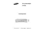
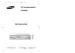
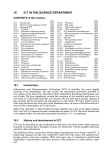
1
PROVED
AP
97
User’s Guide
Bruksanvisning
Guía de Usuario
Flexcams are available in
sizes 15kN, 40kN, 60kN,
90kN, and 150kN. An
accumulator is always
used in the system, which
ensures a suitable system
pressure in regard to
function and safety.
Flexcam finns i storlekarna
15kN, 40kN, 60kN, 90kN
och 150kN. En ackumulator
används alltid i systemet
vilken säkerställer ett lämpligt systemtryck med hänsyn
till funktion och säkerhet.
Product designed and
manufactured according
to Pressure Equipment
Directive (PED) 97/23/EC.
Produkten konstruerad
och tillverkad enligt
Tryckkärlsdirektivet
(PED) 97/23/EG
(AFS 1999:4)
Flexcam está disponible
en los siguientes tamaños:
15kN, 40kN, 60kN, 90kN y
150kN.
El sistema incorpora siempre un acumulador, lo cual
garantiza una adecuada
presión de sistema, para
un óptimo funcionamiento
y seguridad
Este producto ha sido
diseñado y fabricado
conforme a la Directiva
sobre Equipos a Presión
(PED) 97/23/CE
Cam Unit (HCC/CC)
Power Unit (HCP/HCP-S)
Force Cylinder (HCF)
Box 216, SE-573 23 Tranås, Sweden, Tel +46 140 571 00, Telefax +46-140-571 99
8100-8014-01
/2 3/ E C
User’s Guide
Bruksanvisning
Guía de Usuario
För bästa möjliga livslängd och säkerhet, skall
instruktionerna enligt nedan följas. Produkten
används huvudsakligen till klippning, formning
och flänsning av plåt i pressverktyg med
anpassade enheter för respektive operation. Se
även
katalog för vidare
information.
For the greatest possible lifetime and safety,
the following instructions should be followed.
This product is mainly used for cutting, shaping, and flanging sheet metal in press tools
with units adapted to their respective operations. See also the
catalogue for further information.
Para una máxima seguridad y vida útil, seguir las
instrucciones que a continuación se especifican.
Este producto se emplea fundamentalmente para
el corte, perfilado y rebordeado de chapa en herramientas de prensa, con unidades adaptadas a las
diferentes operaciones. Para más información, ver
también el catálogo
θ>0
90˚
Mounting Instructions: Power Unit
(HCP, HCP-S)
Monteringsanvisning Givare
(HCP, HCP-S)
Mount the Power Unit, using four fastening
screws, to a flat surface. The Power Unit can
also be placed upside down. Note that the
Power Unit’s piston is normally striked 10mm
more than the Cam Unit’s/Force Cylinder’s
stroke length. This ensures that the Cam Unit/
Force Cylinder always works with the same
stroke length. As a result, the Accumulator
piston rises about 10mm for each actuation.
The Accumulator for the HCP-S shall be placed
between the Power Unit and the Cam Unit/
Force cylinder. It can be placed at any angle.
- The surface that activates the Power Units
piston shall be flat and perpendicular to the
direction of stroke.
- Ensure that the Power Unit and the accumulator are protected from mechanical damage.
- The space for the Accumulator must be sufficient when the Power Unit’s piston is fully
stroked.
- When powering a wide shuttle, at least two
separate systems should be used in order to
maintain a parallel motion.
Fäst givaren med hjälp av 4 fästskruvar på ett
plant underlag. Givaren kan även placeras upp
och ned vänd. Observera att givarens kolv
normalt aktiveras 10 mm mer än kamenhetens/
kraftcylinderns slaglängd. Detta säkerställer att
kamenheten/kraftcylindern alltid arbetar samma
slaglängd. Ackumulatorkolven lyfter således ca
10 mm vid varje operation.
B
Fijar el transductor con ayuda de cuatro tornillos de
fijación sobre una base plana. El transductor puede
instalarse también en posición invertida. Téngase en
cuenta que el émbolo del transductor tiene
normalmente una carrera 10 mm superior a la de la
unidad de leva/cilindro de fuerza. Ello garantiza una
misma carrera para la unidad de leva y el cilindro de
fuerza. Es decir, el émbolo del acumulador sube unos
10 mm en cada operación.
Ackumulatorn för HCP-S skall placeras mellan
El acumulador del HCP-S debe situarse entre el
givaren och kamenhet/kraftcylinder. Den kan
transductor y la unidad de leva/cilindro de fuerza.
placeras i alla förekommande vinklar.
Puede colocarse en todos los ángulos.
- Ytan som aktiverar givarens kolv skall vara plan - La superficie que activa el émbolo del transductor
och vinkelrät mot rörelsen.
debe ser plana y perpendicular al sentido de
- Tillse att givaren och ackumulatorn skyddas
movimiento.
mot mekaniska skador.
- Asegurarse de que el transductor y el acumulador
- Utrymmet för ackumulatorn måste vara
no sufran daños mecánicos.
tillräckligt då givarens kolv är helt aktiverad.
- Al activarse completamente el émbolo del
- Vid drivning av bred skyttel skall minst två
transductor, el acumulador debe disponer de espacio
separata system användas för att erhålla en
suficiente.
parallell rörelse
- Al operar una lanzadera ancha, se ha de utilizar un
mínimo de dos sistemas independientes para
conseguir un movimiento paralelo.
A
θ>0
90°
Mounting Instructions: Cam Unit
(CC, HCC)
This unit shall be mounted to a flat surface using
all the fastening screws and key grooves. The
guide pins should also be used in order to locate
the unit’s exact position. The Cam Unit can be
mounted at any angle or orientation.
A - The force that the Cam Unit generates shall act
parallel to the Cam Unit’s movement so that no
oblique forces act on the Cam Unit.
B - The force should also work within a limited area
according to the specification in the
catalogue.
- If the Cam Unit is used for flanging or another
operation that generates side loads, suitable
support shall be provided. There is also a Flange
Cam Unit (CCF) available that is specially designed for flanging, with built-in side load support.
Instrucciones de montaje, transductor
(HCP, HCP-S)
δ>0
Monteringsanvisning Kamenhet
(CC, HCC)
Instrucciones de montaje, unidad de leva (CC,
HCC)
Enheten skall monteras på ett plant underlag med
användning av samtliga fästskruvar och kilspår.
Även styrpinnar bör användas för att lokalisera
enhetens position exakt. Kamenheterna kan fritt
monteras i alla förekommande vinklar.
A - Kraften som kamenheten genererar skall verka A
parallellt i linje med kamenhetens rörelse så att
inga sneda krafter påverkar kamenheten.
B - Kraften skall även verka inom ett begränsat
B
område enligt specifikation i
katalog.
La unidad debe ser instalada sobre una base plana, con
todos los tornillos de fijación y chaveteros. Utilizar también clavijas guía para localizar la posición de la unidad
de manera precisa. Las unidades de leva pueden
montarse en todos los ángulos.
- La fuerza generada por la unidad de leva debe ser
paralela al movimiento de la misma, para que la unidad
de leva no se vea afectada por fuerzas oblicuas.
- Asimismo, la fuerza debe ejercerse dentro de un área
limitada, conforme a la especificación del catálogo
.
- Om kamenheten används till flänsning eller
annan operation som genererar sneda krafter skall
lämpligt stöd arrangeras. Det finns även en
kamenhet (CCF) speciellt avsedd för flänsning
med inbyggt stöd.
- En caso de emplear la unidad de leva para
operaciones de rebordeado u otras operaciones que
generen fuerzas oblicuas, emplear un soporte adecuado.
También hay disponible una unidad de leva (CCF)
especialmente diseñada para el rebordeado, que lleva
un soporte incorporado.
User’s Guide
Bruksanvisning
Guía de Usuario
A
θ>0
A
90°
χ=0
SNominal
θ>0
B
Stop
χ>0
Stop
SNominal
Mounting Instructions: Force Cylinder
(HCF)
This unit can be mounted using a flange or a
foot on a flat surface using all the supplied
fastening screws. The Force Cylinder can be
mounted at any angle or orientation.
A – Ensure that the force that the unit generates
acts along the cylinder’s centre line so that no
perpendicular or side load forces act on the
Force Cylinder. A flexible connector, as illustrated above, can be advantageous.
B – Also ensure that the Force Cylinder works
against an external stop that is arranged so
that the utilised stroke length does not exceed
the specified stroke length.
Monteringsanvisning: Kraftcylinder (HCF)
Enheten kan flänsmonteras eller fotmonteras
mot ett plant underlag med användning av
samtliga fästskruvar. Kraftcylindern kan fritt
monteras i alla förekommande vinklar.
A – Tillse att kraften som enheten genererar
verkar längs cylinderns centrumlinje så att
inga sidokrafter eller sneda krafter uppstår på
kraftcylindern. Här kan med fördel en flexibel
koppling användas enligt bild ovan.
B – Tillse även att kraftcylindern arbetar mot ett
externt stopp som arrangeras så att utnyttjad
slaglängd inte överskrider specificerad
slaglängd.
Instrucciones de montaje, cilindro de fuerza
(HCF)
Esta unidad puede montarse en brida o sobre pie,
en una base plana, con todos los tornillos de
fijación. El cilindro de fuerza puede instalarse en
todos los ángulos.
A - Asegurarse de que la fuerza generada por el
cilindro se ejerza por el eje de simetría del mismo,
evitando así fuerzas laterales u oblicuas. Es
recomendable emplear un acoplamiento flexible,
según se muestra en la imagen encima.
B - Asimismo, el cilindro de fuerza debe operar
contra un tope externo, dispuesto de manera que
la carrera real no sea superior a la especificada
para el cilindro.
Mounting Instructions: Hose System
Monteringsanvisning Slangsystem
Instrucciones de montaje, sistema de mangas
Ensure that the protective plugs on the hoses
and units are retained for as long as possible
during installation. No foreign particles may be
found in the System. Ensure that all edges near
the Hoses are well rounded as the Hoses can
move during operation. Note the minimum
recommended bending radii for the hoses.
Tillse att slangarnas och enheternas pluggar
är monterade så länge som möjligt under
installationen. Inga främmande partiklar får
förekomma i systemet. Tillse att alla kanter
nära slangen rundas ordentligt eftersom
slangen kan röra sig något under drift. Notera
slangens minsta rekommenderade
böjningsradier
Asegurarse de que las mangas y los tapones de
las unidades estén montados el mayor tiempo
posible durante la instalación. Es fundamental que
no penetren partículas extrañas en el sistema.
Redondear adecuadamente todos los bordes
contiguos a la manga, ya que ésta puede moverse
ligeramente durante la operación. Tener en cuenta
los radios de curvatura mínimos recomendados
para la manga.
Se
tion.
Para más información, ver
See
tion.
for further informa-
för vidare informa-
.
Operating Instructions
The system is filled with nitrogen gas and fluid
according to the instructions in the
catalogue. Ensure that the filling
pressure is not exceeded and that other operating data are kept within the specifications provided.
Driftanvisningar
Systemet fylls med kvävgas och olja enligt
instruktioner i
katalog.
Tillse att fylltrycken inte överskrids och att
övriga driftdata innehålls enligt angivna
specifikationer.
Instrucciones de operación
El sistema se llena de gas nitrógeno y aceite
conforme a las instrucciones del catálogo
. Poner cuidado en no superar
la presión de llenado y en respetar los demás
datos operativos indicados en las especificaciones.
See Basic Information further on.
Se Basfakta nedan.
Ver Datos básicos, más abajo.
Service/Maintenance
If installed and operated correctly, you can
expect long service intervals. The number of
operating cycles between servicing and the
total lifetime vary in accordance with the application. Contact your distributor for help with
service or maintenance.
Service/ Underhåll
Vid korrekt installation och drift kan man
räkna med en lång livslängd mellan
serviceintervallerna. Antal arbetscykler mellan
service och total livslängd varierar i
omfattning beroende på applikation. Kontakta
Er återförsäljare vid behov av service eller
underhåll.
Servicio/Mantenimiento
Si la instalación y operación son correctas, se
obtendrá una prolongada vida útil entre los
intervalos de servicio. El número de ciclos de
funcionamiento entre las intervenciones de servicio
y la vida útil total varían de acuerdo a la aplicación
de que se trate. En caso de precisar servicio o
mantenimiento, consulte con su concesionario.
Varning!
Underhållsarbetet får bara utföras av speciellt
utbildad personal med mycket god
produktkännedom. Misstag vid montering
eller fyllning kan äventyra säkerheten och/
eller förkorta produktens livslängd.
Advertencia!
Las tareas de mantenimiento sólo pueden ser
efectuadas por personal especializado con un
excelente conocimiento del producto. Los errores
durante el montaje o llenado pueden perjudicar el
nivel de seguridad y/o reducir la vida útil del
producto.
Warning!
Maintenance work may only be carried out by
specially trained personnel with very good
product knowledge. Mistakes during mounting
or charging can lead to safety risks and/or
shorten the product’s lifetime.
For more information, see the
catalogue, www.stromsholmen.com,
or contact your distributor.
För mer info se
katalog,
www.stromsholmen.com eller kontakta din
återförsäljare.
Caution! Do not modify the product in any way.
Para más información, vea el catálogo
, visite www.stromsholmen.com o
consulte con su concesionario.
Varning! Produkten får inte modifieras.
Advertencia! No modifique el producto.
User’s Guide
Bruksanvisning
Guía de Usuario
Datos básicos
Basfakta
Basic Information
Tryckmedium .................................
Pressure medium ..........................
Nitrogen gas N2
Oil type ..........................................
......................................................
Oljetyp ...........................................
DIN 51524
HVLP, ISO VG32 ......................................................
Fluid purity .....................................
......................................................
......................................................
ISO 4406 15/12
(filtration grade
10µm)
Renhet olja ....................................
......................................................
......................................................
Gas nitrógeno N2
Tipo de aceite ................................
DIN 51524
HVLP, ISO VG32 ......................................................
DIN 51524
HVLP, ISO VG32
Pureza del aceite ...........................
......................................................
......................................................
ISO 4406 15/12
(grado de
filtración: 10 µm)
ISO 4406 15/12
(filtreringsgrad
10 µm)
En casos especiales, pueden permitirse
valores distintos a los especificados, así como
en determinadas combinaciones de carrera,
velocidad y frecuencia. Para más información,
consulte con su concesionario.
Andra värden än specificerade kan tillåtas i
speciella fall eller kombinationer av slaglängder, hastigheter och frekvens. Kontakta
er återförsäljare för vidare information.
Values other than those specified can be
permitted in special cases for stroke length,
speed, and frequency combinations. Contact
your distributor for further information.
Description
Medio de presión ...........................
Kvävgas N2
Unit
Cam/Force cylinder
Compact cam
Power Unit
HCC/HCF
CC
HCP
Force (size)
kN
15
40
60
90
150
15
40
90
15
40
60
90
150
Initial return force
kN
2
5
8
13
21
2
4
10
—
—
—
—
—
Max. frequency
Op./min
30
Max. speed
m/s
0.8
0.8
0.8
Max. return speed
m/s
0.8
0.8
0.8
Min. gas press.
Bar
20
125
105
50
Max. gas press.
Bar
40
180
150
180
Stroke
mm
25, 50, 100
24, 49, 99 *
35, 60, 110, 160 **
Ambient temperature
°C
10 - 40
10 - 40
10 - 40
* Does not apply to CC 015
60
30
60
30
** Does not apply to HCP 015 and HCP 150
Product Marking / Produktmärkning / Marcación de producto
(HCP and HCP-A Accumulators)
KALLER HCP XXX1-YYY2
Vx.x3L
PCHARGE MAX 180BAR AT 20°C
TS-20/80°C PS 0/yyy4BAR
DPMAX zzz5BAR FLUID/N2 GR2
MADE IN SWEDEN
HCP:
1
XXX
(Size)
2
060
090
150
HCP-A:
KALLER HCP-A XXX1-YYY2
Vx.x3L
PCHARGE MAX 180BAR AT 20°C
TS-20/80°C PS 0/yyy4BAR
DPMAX zzz5BAR FLUID/N2 GR2
MADE IN SWEDEN
x.x (Volume)
3
[L]
YYY (PS)
4
[bar]
ZZZ (∆ P)
5
[bar]
(PT)
[bar]
35
0.5
307
90
439
60
0.8
307
90
439
110
1.3
307
90
439
160
1.8
307
90
439
35
0.9
307
90
439
60
1.3
307
90
439
110
2.1
307
90
439
160
2.9
307
90
439
35
1.5
277
60
396
60
2.1
277
60
396
110
3.3
277
60
396
YYY
(Stroke)
PS: Design pressure for the Accumulator
PT: Test pressure for the Accumulator
DP: Maximal difference pressure
PS: Beräkningstryck för aktuell Ackumulator
PT: Provtryck för aktuell Ackumulator
DP: Maximal differens tryck
PS: Presión estimada del acumulador
PT: Presión de ensayo del acumulador
DP: Presión diferenciado máx
For more information, see the
catalogue,
www.stromsholmen.com, or
contact your distributor.
För mer information se
katalog,
www.stromsholmen.com eller
kontakta din återförsäljare.
Para más información, ver
el catálogo,
visitar www.stromsholmen.com o
contacte con su concesionario.