1
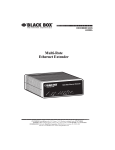
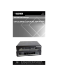
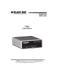
OCTOBER 1998
ME530A
WAN Bridge Module
CUSTOMER SUPPORT INFORMATION
To order or for technical support: Call 724-746-5500 or fax 724-746-0746
Technical support and fax orders 24 hours a day, 7 days a week
Phone orders 24 hours, 7 A.M. Monday to midnight Friday; Saturday 8 to 4 (Eastern)
Mail order: Black Box Corporation, 1000 Park Drive, Lawrence, PA 15055-1018
Web site: http://www.blackbox.com • E-mail: [email protected]
WAN BRIDGE MODULE
FEDERAL COMMUNICATIONS COMMISSION
AND
CANADIAN DEPARTMENT OF COMMUNICATIONS
RADIO FREQUENCY INTERFERENCE STATEMENTS
This equipment generates, uses, and can radiate radio frequency energy and if
not installed and used properly, that is, in strict accordance with the
manufacturer’s instructions, may cause interference to radio communication. It
has been tested and found to comply with the limits for a Class A computing
device in accordance with the specifications in Subpart J of Part 15 of FCC rules,
which are designed to provide reasonable protection against such interference
when the equipment is operated in a commercial environment. Operation of
this equipment in a residential area is likely to cause interference, in which case
the user at his own expense will be required to take whatever measures may be
necessary to correct the interference.
Changes or modifications not expressly approved by the party responsible for
compliance could void the user’s authority to operate the equipment.
This digital apparatus does not exceed the Class A limits for radio noise emission from
digital apparatus set out in the Radio Interference Regulation of the Canadian Department
of Communications.
Le présent appareil numérique n’émet pas de bruits radioélectriques dépassant les limites
applicables aux appareils numériques de classe A prescrites dans le Règlement sur le
brouillage radioélectrique publié par le ministère des Communications du Canada.
The CE symbol on your equipment indicates that it complies with the
Electromagnetic Compatibility (EMC) directive and the Low Voltage Directive
(LVD) of the Union European (EU).
1
WAN BRIDGE MODULE
NORMAS OFICIALES MEXICANAS (NOM)
ELECTRICAL SAFETY STATEMENT
INSTRUCCIONES DE SEGURIDAD
1. Todas las instrucciones de seguridad y operación deberán ser leídas antes
de que el aparato eléctrico sea operado.
2. Las instrucciones de seguridad y operación deberán ser guardadas para
referencia futura.
3. Todas las advertencias en el aparato eléctrico y en sus instrucciones de
operación deben ser respetadas.
4. Todas las instrucciones de operación y uso deben ser seguidas.
5. El aparato eléctrico no deberá ser usado cerca del agua—por ejemplo,
cerca de la tina de baño, lavabo, sótano mojado o cerca de una alberca,
etc..
6. El aparato eléctrico debe ser usado únicamente con carritos o pedestales
que sean recomendados por el fabricante.
7. El aparato eléctrico debe ser montado a la pared o al techo sólo como sea
recomendado por el fabricante.
8. Servicio—El usuario no debe intentar dar servicio al equipo eléctrico más
allá a lo descrito en las instrucciones de operación. Todo otro servicio
deberá ser referido a personal de servicio calificado.
9. El aparato eléctrico debe ser situado de tal manera que su posición no
interfiera su uso. La colocación del aparato eléctrico sobre una cama,
sofá, alfombra o superficie similar puede bloquea la ventilación, no se
debe colocar en libreros o gabinetes que impidan el flujo de aire por los
orificios de ventilación.
2
WAN BRIDGE MODULE
10. El equipo eléctrico deber ser situado fuera del alcance de fuentes de calor
como radiadores, registros de calor, estufas u otros aparatos (incluyendo
amplificadores) que producen calor.
11. El aparato eléctrico deberá ser connectado a una fuente de poder sólo del
tipo descrito en el instructivo de operación, o como se indique en el
aparato.
12. Precaución debe ser tomada de tal manera que la tierra fisica y la
polarización del equipo no sea eliminada.
13. Los cables de la fuente de poder deben ser guiados de tal manera que no
sean pisados ni pellizcados por objetos colocados sobre o contra ellos,
poniendo particular atención a los contactos y receptáculos donde salen
del aparato.
14. El equipo eléctrico debe ser limpiado únicamente de acuerdo a las
recomendaciones del fabricante.
15. En caso de existir, una antena externa deberá ser localizada lejos de las
lineas de energia.
16. El cable de corriente deberá ser desconectado del cuando el equipo no
sea usado por un largo periodo de tiempo.
17. Cuidado debe ser tomado de tal manera que objectos liquidos no sean
derramados sobre la cubierta u orificios de ventilación.
18. Servicio por personal calificado deberá ser provisto cuando:
A:
El cable de poder o el contacto ha sido dañado; u
B:
Objectos han caído o líquido ha sido derramado dentro del
aparato; o
C:
El aparato ha sido expuesto a la lluvia; o
D:
El aparato parece no operar normalmente o muestra un cambio en
su desempeño; o
E:
El aparato ha sido tirado o su cubierta ha sido dañada.
3
WAN BRIDGE MODULE
TRADEMARKS
The trademarks mentioned in this manual are the sole
property of their owners.
4
WAN BRIDGE MODULE
Contents
Chapter
Page
1. Specifications. . . . . . . . . . . . . . . . . . . . . . . . . . . . . . 7
2. Introduction . . . . . . . . . . . . . . . . . . . . . . . . . . . . . . 8
2.1 Description . . . . . . . . . . . . . . . . . . . . . . . . . . . . 8
2.2 Features . . . . . . . . . . . . . . . . . . . . . . . . . . . . . . . 8
2.3 Typical Application . . . . . . . . . . . . . . . . . . . . . . 9
3. Configuration . . . . . . . . . . . . . . . . . . . . . . . . . . . . . 11
4. Installation. . . . . . . . . . . . . . . . . . . . . . . . . . . . . . . . 13
4.1 Installing the Module . . . . . . . . . . . . . . . . . . . . 13
4.1.1 Removing the Existing Module . . . . . . . . 13
4.1.2 Installing the New WAN Bridge
Module . . . . . . . . . . . . . . . . . . . . . . . . . . . 14
4.2 Connecting to the 10BASE-T
Ethernet Port . . . . . . . . . . . . . . . . . . . . . . . . . . . 15
4.2.1 Connecting the 10BASE-T
Ethernet Port to a Hub . . . . . . . . . . . . . . 16
4.2.2 Connecting the 10BASE-T
Ethernet Port to a PC (DTE). . . . . . . . . . 17
5
WAN BRIDGE MODULE
Chapter
Page
4.3 Connection to the Line-Interface Media. . . . . 17
4.4 Connecting to AC Power . . . . . . . . . . . . . . . . . 18
5. Operation . . . . . . . . . . . . . . . . . . . . . . . . . . . . . . . . 19
5.1 Operating Instructions . . . . . . . . . . . . . . . . . . . 19
5.2 Power-On . . . . . . . . . . . . . . . . . . . . . . . . . . . . . . 19
5.3 LED Status Monitors . . . . . . . . . . . . . . . . . . . . . 20
Appendix: Interface Pin Assignment. . . . . . . . . . . . . 22
6
WAN BRIDGE MODULE
1. Specifications
LAN Connection—RJ-45, 10BASE-T, 802.3 Ethernet
MAC Address Table Size—4096 entries
MAC Address Aging—MAC addresses deleted after
8 minutes of inactivity
On-Board Memory—512 KB RAM; 128 KB FLASH
Frame Latency—1 frame
Interface—Card-edge connection to module port
on base unit
LED Indicators—(1) General Status, (1) Link
Integrity
Power Supply—+5 Volts @ 510 mA supplied to
module from interface
Temperature—32 to 122 °F (0 to 50 °C)
Size—2.9" x 3.2" (7.4 x 8.1 cm)
Weight—0.25 lb. (0.11 kg)
7
WAN BRIDGE MODULE
2. Introduction
2.1 Description
The WAN Bridge Module (ME530A) installs in copper
(part number ME485A/E) and fiber (part numbers
ME620A and ME621A) base units to provide seamless
Ethernet LAN extension. The Module performs the
bridging function between two physically separate
Ethernet LANs at the MAC level. Operation of the
Module is transparent to higher network level protocols
such as TCP/IP, DECnet, NETBIOS, and IPX.
Once installed in the local base unit, this plug-andplay Module forwards LAN broadcasts, multicasts, and
frames destined for the peered Ethernet LAN at the
remote end (the base unit at the remote end must also
be equipped with a WAN Bridge Module). Using the
Module, peered Ethernet LANs can be linked over
leased 4-wire and campus fiber circuits.
2.2 Features
• Installs in copper (part number ME485A/E) and
fiber (part numbers ME620A and ME621A) base
units.
8
WAN BRIDGE MODULE
• Provides MAC-level connection between two
peered Ethernet LANs
• Operates transparently to higher-level protocols
such as TCP/IP, DECnet, NETBIOS, and IPX
• No configuration necessary
• Automatically discovers, loads, and deletes MAC
addresses
• 512 KB on-board RAM
• Modular 10BASE-T connection (RJ-45)
• Two LED indicators: status and link integrity
2.3 Typical Application
The WAN Bridge Module is designed to plug directly
into the rear of a modular campus driver (part number
ME485A/E, ME620A, or ME621A). The Module is
designed to be used as one of a pair of units. Figure 2-1
illustrates a typical WAN Bridge Module installation.
9
WAN BRIDGE MODULE
Corporate Headquarters
LAN
Ethernet WAN
Bridge Module
Ethernet WAN
Bridge Module
DDS Network
PCM Network
768k Leased Line
512k Leased Line
128k Leased Line
64k Leased Line
128 k Single Fiber
256k Single Fiber
Figure 2-1. Typical WAN Bridge Module application.
LAN
10
WAN BRIDGE MODULE
3. Configuration
The WAN Bridge Module plugs into fiber and copper
campus drivers to extend Ethernet LANs. The Module
has no switches or jumpers and does not need to be
configured. However, factors such as type of medium,
throughput across the link, and clocking mode must be
determined by the settings of the baseband modems.
Please refer to the manual for your campus driver (part
number ME485A/E, ME620A, or ME621A) to make the
following settings.
1. Bit Rate: The DTE rate setting of your base unit
corresponds to the throughput of your WAN
Bridge Module. Use higher speeds to allow
maximum throughput to your extended LAN.
Using lower speeds limits the access of your
extended LAN.
2. Clocking Mode: Set the clocking modes on the
base units so that one unit is configured for
internal clocking mode and the other unit is set
for Receive Recover clocking mode.
11
WAN BRIDGE MODULE
Base-Unit Clock Modes.
Unit “A”
Unit “B”
Internal Clock Setting
Receive Recover Clock Setting
NOTE: Unit “A” and unit “B” are arbitrarily chosen. It does not matter which unit is
“A” and which is “B.”
3. All other base-unit settings depend on your
application and on the application medium
(twisted pair or fiber cable).
12
WAN BRIDGE MODULE
4. Installation
The WAN Bridge Module is completely plug and play.
This section tells you how to make the connections.
4.1 Installing the Module
Each Module has a 50-pin card-edge connector on one
side and an Ethernet interface on the other. The
instructions below describe how to remove the existing
module and how to install the new WAN Bridge Module.
If your base unit does not have an existing module
already installed, please skip to Section 4.1.2.
4.1.1 REMOVING THE EXISTING MODULE
1. Turn the power switch off. Leave the power cord
plugged into a grounded outlet to keep the unit
grounded.
2. Loosen the two thumbscrews on the module by
turning them counterclockwise.
3. Grasp the two thumbscrews and gently pull the
module from the unit. Apply equal force to the
thumbscrews to keep the module straight during
the removal process.
13
WAN BRIDGE MODULE
4.1.2 INSTALLING THE NEW WAN BRIDGE MODULE
1. Make sure the power switch on the base unit is off.
Leave the power cord plugged into a grounded
outlet to keep the unit grounded.
2. Hold the Module with the faceplate toward you
and align the Module with the guide slots in the
rear panel of the base unit.
3. While keeping the Module’s faceplate parallel with
the base unit rear panel, slide the Module straight
in—so that the card edge contacts line up with the
socket inside the chassis. Figure 4-1 shows how a
Module plugs into the rear of the base unit.
Figure 4-1. Installation of a WAN Bridge Module.
14
WAN BRIDGE MODULE
NOTE
The card-edge connector should meet the socket when the
Module is almost all the way into the chassis. If you
encounter a lot of resistance, remove the Module and
repeat steps 2 and 3.
4. With the card-edge contacts aligned with the
socket, firmly seat the Module by using your
thumbs to apply pressure directly to the right and
left edges of the Module faceplate. Applying
moderate and even pressure should be sufficient
to seat the Module. You should hear it “click” into
place.
5. To secure the Module in place, push the
thumbscrews into the chassis and turn the screws
clockwise to tighten.
4.2 Connecting to the 10BASE-T Ethernet Port
The RJ-45 Ethernet port on the WAN Bridge Module is
designed to connect directly to a 10BASE-T network.
Figure 4-2 shows the 10BASE-T RJ-45 port pin
description. You may make connections up to 328 feet
(100 m) using Type 4 or 5 cable.
15
WAN BRIDGE MODULE
1
2
3
4
5
6
7
8
1 TD+ (data output from IM1/I)
2 TD- (data output from IM1/I)
3 RD+ (data input to IM1/I)
4 (no connection)
5 (no connection)
6 RD- (data input to IM1/I)
7 (no connection)
8 (no connection)
Figure 4-2. WAN Bridge Module RJ-45 connector pinout.
4.2.1 CONNECTING THE 10BASE-T ETHERNET PORT TO A HUB
The WAN Bridge Module interface is configured as DTE
(Data Terminal Equipment), just like a 10BASE-T
network interface card in a PC. Therefore, it “expects”
to connect to a 10BASE-T Hub using a straight-through
RJ-45 cable. Use Figure 4-3 to construct a cable to
connect the Module to a 10BASE-T Hub.
Bridge Module RJ-45 Pin No.
10BASE-T Hub RJ-45 Pin. No.
1 (TX+)
2 (TX-)
1 (RX+)
2 (RX-)
3 (RX+)
6 (RX-)
3 (TX+)
6 (TX-)
Figure 4-3. Module-to-Hub cable pinning.
16
WAN BRIDGE MODULE
4.2.2 CONNECTING THE 10BASE-T ETHERNET PORT TO A PC
(DTE)
The WAN Bridge Module interface is configured as DTE
(Data Terminal Equipment). If you wish to connect the
Module to another DTE device such as a 10BASE-T
network interface card in a PC, you must construct a
10BASE-T crossover cable as shown in Figure 4-4.
Bridge Module RJ-45 Pin No.
PC with 10BASE-T NIC Installed Pin No.
1 (TX+)
2 (TX-)
1 (TX+)
2 (TX-)
3 (RX+)
6 (RX-)
3 (RX+)
6 (RX-)
Figure 4-4. Module-to-PC cable pinning.
4.3 Connection to the Line-Interface Media
Instructions for connecting the line-interface media
(twisted pair or fiberoptic cable) are contained in the
manual for the base unit (ME485A/E, ME620A, or
ME621A). Please refer to the base-unit manual for
connection details.
NOTICE
Any terminal cable connected to the WAN Bridge Module
must be shielded cable, and the outer shield must be 360degree bonded—at both ends—to a metal or metalized
backshelf.
17
WAN BRIDGE MODULE
4.4 Connecting to AC Power
Instructions for connecting the Universal Interface
power supply are contained in the manual for the base
unit (part number ME485A/E, ME620A, or ME621A).
Please refer to the base unit manual for connection
details.
WARNING
The WAN Bridge Module has been specifically designed to
work with Universal Interface version of the base unit. Use
with 120/230 VAC versions could damage the unit. If you
are not sure which power supply your base unit uses,
please contact Black Box Technical Support at
724-746-5500.
18
WAN BRIDGE MODULE
5. Operation
Once the WAN Bridge Module is installed, it should
operate transparently. This section describes power-on,
general operating instructions, and the LED status
monitors.
5.1 Operating Instructions
In order to operate, the WAN Bridge Module must be
installed in the base unit. It also requires a 10BASE-T
connection. After power is applied, the Module
automatically starts bridging without further user
intervention. MAC addresses discovered are
automatically loaded into the MAC address table. They
are automatically deleted from the MAC address table if
they are inactive for 8 minutes.
5.2 Power-On
Before applying power to the Module, please be sure it is
properly installed in the base unit. Then make sure that
unit is connected to the appropriate power source
(Universal Interface AC Power Supply or DC Power
Supply). Then power on the base unit using the rear
power switch.
19
WAN BRIDGE MODULE
5.3 LED Status Monitors
The WAN Bridge Module features two LEDs that
monitor general operating status and the integrity of the
10BASE-T twisted-pair link. Figure 5-1 shows the LEDs
located directly beneath the RJ-45 jack. Following
Figure 5-1 is a description of each LED’s function.
WAN Bridge Module
Link LED
Link LED
Interface Port
Figure 5-1. WAN Bridge Module panel.
• Status: Blinks yellow from one to four times to
indicate system status. Each pulse pattern is
separated by a two second “off” period. Greater
pulse patterns have higher priority (buffer
saturation has greater priority than an empty MAC
table). Valid system statuses are:
1 pulse=system status is okay
20
WAN BRIDGE MODULE
2 pulses=no MAC entires in the MAC Address
Table
3 pulses=Clear to Send (CTS) or Carrier Detect
(DCD) from base unit are not asserted
4 pulses=WAN Bridge Module buffer is saturated
• Link: Glows green to indicate good link integrity
on the 10BASE-T twisted-pair line.
21
WAN BRIDGE MODULE
Appendix: Interface Bridge
Module
22
Pin #1
Signal
1
2
3
4
5
6
7
8
TD+ (data output from WAN Bridge Module)
TD- (data output from WAN Bridge Module)
RD+ (data input to WAN Bridge Module)
no connection
no connection
RD- (data input to WAN Bridge Module)
no connection
no connection
© Copyright 1998. Black Box Corporation. All rights reserved.
1000 Park Drive • Lawrence, PA 15055-1018 • 724-746-5500 • Fax 724-746-0746