1
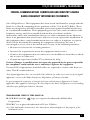
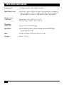
JUNE 2002
IC443A-R2
Video Mono Audio Baluns
onoun
o MB
l
e
d
i
V udio a
A
O2
VIDE IR 3
IO 22 PA(1 & 2)
D
U
1 A PAIR& 6)
(3
IDEO 4
1 V PAIR& 8)
O
I
(7
AUDAIR 1
P & 5)
(4
CUSTOMER
SUPPORT
INFORMATION
Order toll-free in the U.S.: Call 877-877-BBOX (outside U.S. call 724-746-5500)
FREE technical support 24 hours a day, 7 days a week: Call 724-746-5500 or fax 724-746-0746
Mailing address: Black Box Corporation, 1000 Park Drive, Lawrence, PA 15055-1018
Web site: www.blackbox.com • E-mail: [email protected]
FCC/IC RFI STATEMENTS, TRADEMARKS
FEDERAL COMMUNICATIONS COMMISSION AND INDUSTRY CANADA
RADIO-FREQUENCY INTERFERENCE STATEMENTS
Class B Digital Device. This equipment has been tested and found to comply with the
limits for a Class B computing device pursuant to Part 15 of the FCC Rules. These
limits are designed to provide reasonable protection against harmful interference
in a residential installation. This equipment generates, uses, and can radiate radio
frequency energy and, if not installed and used in accordance with the
instructions, may cause harmful interference to radio communications. However,
there is no guarantee that interference will not occur in a particular installation. If
this equipment does cause harmful interference to radio or telephone reception,
which can be determined by turning the equipment off and on, the user is
encouraged to try to correct the interference by one of the following measures:
• Reorient or relocate the receiving antenna.
• Increase the separation between the equipment and receiver.
• Connect the equipment into an outlet on a circuit different from that to which
the receiver is connected.
• Consult an experienced radio/TV technician for help.
Caution: Changes or modifications not expressly approved by the party responsible
for compliance could void the user’s authority to operate the equipment.
To meet FCC requirements, shielded cables are required to connect this device to
other Class B certified devices.
This digital apparatus does not exceed the Class B limits for radio noise emission from digital
apparatus set out in the Radio Interference Regulation of Industry Canada.
Le présent appareil numérique n’émet pas de bruits radioélectriques dépassant les limites
applicables aux appareils numériques de classe B prescrites dans le Règlement sur le brouillage
radioélectrique publié par Industrie Canada.
TRADEMARKS USED IN THIS MANUAL
BLACK BOX and the
Corporation.
logo are registered trademarks of Black Box
VELCRO® is a registered trademark of Velcro USA Inc.
Any other trademarks mentioned in this manual are acknowledged to be the property of the
trademark owners.
1
VIDEO MONO AUDIO BALUNS
NORMAS OFICIALES MEXICANAS (NOM)
ELECTRICAL SAFETY STATEMENT
INSTRUCCIONES DE SEGURIDAD
1. Todas las instrucciones de seguridad y operación deberán ser leídas antes de
que el aparato eléctrico sea operado.
2. Las instrucciones de seguridad y operación deberán ser guardadas para
referencia futura.
3. Todas las advertencias en el aparato eléctrico y en sus instrucciones de
operación deben ser respetadas.
4. Todas las instrucciones de operación y uso deben ser seguidas.
5. El aparato eléctrico no deberá ser usado cerca del agua—por ejemplo, cerca
de la tina de baño, lavabo, sótano mojado o cerca de una alberca, etc..
6. El aparato eléctrico debe ser usado únicamente con carritos o pedestales que
sean recomendados por el fabricante.
7. El aparato eléctrico debe ser montado a la pared o al techo sólo como sea
recomendado por el fabricante.
8. Servicio—El usuario no debe intentar dar servicio al equipo eléctrico más allá
a lo descrito en las instrucciones de operación. Todo otro servicio deberá ser
referido a personal de servicio calificado.
9. El aparato eléctrico debe ser situado de tal manera que su posición no
interfiera su uso. La colocación del aparato eléctrico sobre una cama, sofá,
alfombra o superficie similar puede bloquea la ventilación, no se debe colocar
en libreros o gabinetes que impidan el flujo de aire por los orificios de
ventilación.
10. El equipo eléctrico deber ser situado fuera del alcance de fuentes de calor
como radiadores, registros de calor, estufas u otros aparatos (incluyendo
amplificadores) que producen calor.
11. El aparato eléctrico deberá ser connectado a una fuente de poder sólo del
tipo descrito en el instructivo de operación, o como se indique en el aparato.
2
NOM STATEMENT
12. Precaución debe ser tomada de tal manera que la tierra fisica y la polarización
del equipo no sea eliminada.
13. Los cables de la fuente de poder deben ser guiados de tal manera que no
sean pisados ni pellizcados por objetos colocados sobre o contra ellos,
poniendo particular atención a los contactos y receptáculos donde salen del
aparato.
14. El equipo eléctrico debe ser limpiado únicamente de acuerdo a las
recomendaciones del fabricante.
15. En caso de existir, una antena externa deberá ser localizada lejos de las lineas
de energia.
16. El cable de corriente deberá ser desconectado del cuando el equipo no sea
usado por un largo periodo de tiempo.
17. Cuidado debe ser tomado de tal manera que objectos liquidos no sean
derramados sobre la cubierta u orificios de ventilación.
18. Servicio por personal calificado deberá ser provisto cuando:
A: El cable de poder o el contacto ha sido dañado; u
B: Objectos han caído o líquido ha sido derramado dentro del aparato; o
C: El aparato ha sido expuesto a la lluvia; o
D: El aparato parece no operar normalmente o muestra un cambio en su
desempeño; o
E: El aparato ha sido tirado o su cubierta ha sido dañada.
3
VIDEO MONO AUDIO BALUNS
Contents
Chapter
Page
1.
Specifications ............................................................................................. 5
2.
Introduction ............................................................................................... 7
3.
Installation .................................................................................................. 8
4.
Troubleshooting ......................................................................................
4.1 Things to Try If Problems Occur .....................................................
4.2 Calling Black Box ..............................................................................
4.3 Shipping and Packaging ...................................................................
4
11
11
12
12
CHAPTER 1: Specifications
1. Specifications
Cable Required:
Between Balun pairs: Unshielded twisted pair (UTP):
Construction Standard: Category 3 or higher;
Gauge: 24 AWG or lower;
Termination: RJ-45 plugs;
Pairs: Four (8 wires used) to carry all video and audio
channels;
Impedance: 100 ohms at 1 MHz;
Maximum Capacitance: 20 pF/ft. (6.1 pF/m);
Maximum Attenuation: 6.6 dB/1000 ft. (2 dB/km);
To attached devices:
Video: (1) Standard 75-ohm RG-59/U coaxial cable with a
BNC male connector on the Balun end;
Audio: (2) Standard RCA phono cables
Compliance:
FCC Class B, IC Class/classe B;
CISPR Pub. 22 Class B
Standard:
Composite (baseband) video: NTSC, PAL, or SECAM
Impedance:
Coaxial side: 75 ohms;
Phono side: 600 ohms;
UTP side: 100 ohms
Bandwidth:
Video: DC to 8 MHz;
Audio: 20 Hz to 50 kHz
Maximum RF
Input:
1.1 volts at 60 Hz
Insertion Loss:
Less than 2 dB over the DC-to-8-MHz frequency range
Return Loss:
Greater than 15 dB over the DC-to-8-MHz frequency range
Common-Mode
Rejection:
Greater than 40 dB at 8 MHz
Maximum
Distance:
With Category 3 cable: 1200 ft. (365.8 m) for color video,
1500 ft. (457.2 m) for black & white video;
With Category 5 cable: 2200 ft. (670.6 m) for color video,
2500 ft. (762 m) for black & white video
5
VIDEO MONO AUDIO BALUNS
Connectors:
(1) RJ-45 female and (4) RCA female
RJ-45 Pins Used:
All: Pin 1 is video 2, Pin 2 is video 2 ground, Pin 3 is audio 2,
Pin 4 is audio 1,. Pin 5 is audio 1 ground, Pin 6 is audio 2
ground, Pin 7 is video 1, and Pin 8 is video 1 ground
Temperature
Tolerance:
Humidity
Tolerance:
Operating: 32 to 131˚F (0 to 55˚C);
Storage: -4 to +185˚F (-20 to +85˚C)
Up to 95% noncondensing
Enclosure:
Fire-retardant plastic with included optional VELCRO®
mounting material
Size:
2.3"H x 2.4"W x 1"D (5.8 x 6.1 x 2.5 cm)
Weight:
2.8 oz. (79.3 g)
6
CHAPTER 2: Introduction
2. Introduction
With the Video Mono Audio Balun, you can transmit two pairs of composite
baseband video and mono audio signals across Category 3 or better unshielded
twisted-pair (UTP) cable, which is already wired into most commercial sites. Use
pairs of Baluns to transmit composite video with mono audio: In a normal two-way
(full-duplex) application, the Balun on each end takes a single composite
baseband video signal and a monaural audio signal from 600-ohm RCA type phono
cables, converts the signals, and transmits them over UTP cable to the other Balun,
which converts them back and sends them to their destination. (If your application
needs both sets of signals to travel in the same direction, the Baluns can do this
too.)
Connect the Video Mono Audio Balun to a site’s structured cabling through a
modular wall jack in the work area. Each Balun has four RCA connectors at one
end and an RJ-45 jack at the other end.
The Video Mono Audio Balun is designed for use with CCTV cameras and
monitors, videocassette recorders, camcorders, and other baseband audiovisual
equipment, but is especially useful in two-way videoconferencing applications.
7
VIDEO MONO AUDIO BALUNS
3. Installation
To install a pair of Video Mono Audio Baluns, take these steps:
CAUTION!
Do not attempt to open the housing. There are no user-serviceable parts
inside the Video Mono Audio Balun. Opening the unit will void your
warranty.
1. Make sure that the video devices at either end are not too far away from each
other (refer to the Maximum Distance specification in Chapter 1). If either
device is beyond the reach of the Balun at the other end, the signals the
device receives will be weak or nonexistent.
2. Follow the manufacturer’s instructions for (a) turning off power to the video
and audio equipment you will be attaching and (b) disconnecting that
equipment from AC power and from all other devices.
3. Make certain that the telecommunications outlets and cross-connects to
which you will connect the Baluns are configured properly and are labeled so
that the circuit can be identified.
CAUTION!
Do not connect the Video Mono Audio Balun to a telecommunication
outlet wired to unrelated equipment. Making such a connection may
damage the equipment and/or the Balun. Make sure that all wiring is
straight-through-pinned.
4. Verify that the twisted-pair circuit you want to use is not already being used
for other LAN or telephone equipment.
5. Optional: Each Balun comes with VELCRO® mounting pads. To mount a
Balun to a surface, first make sure that that surface is free of dust, oil, etc., so
the VELCRO will adhere to it. Then peel off the adhesive backing, attach one
side of the pads to the Balun, and attach the other side to the surface.
CAUTION!
Do not mount the Balun over equipment-ventilation openings. Doing so
might damage the Balun or cause the equipment to overheat.
8
CHAPTER 3: Installation
6A. If your application is two-way (that is, one pair of audio/video signals going one
direction and one pair going the other direction): Run four RCA phono cables from
each Balun to the attached device:
• one from the Balun’s VIDEO 1 port to the device’s VIDEO AUX IN port;
• one from the Balun’s VIDEO 2 port to the device’s VIDEO AUX OUT port;
• one from the Balun’s AUDIO 1 port to the device’s AUDIO IN port; and
• one from the Balun’s AUDIO 2 port to the device’s AUDIO OUT port.
(These cables must have RCA male connectors on the Balun end.) Make sure
that the VIDEO IN and AUDIO IN ports of the device on one end of the link
are connected to the VIDEO OUT and AUDIO OUT ports of the device on
the other end. Refer to Figure 3-1.
6B. If your application is one-way (that is, both pairs of audio/video signals going the same
direction): Run four RCA phono cables from each Balun to the attached
devices:
• On the source end, these cables should go from the Balun’s VIDEO and
AUDIO ports to the devices’ VIDEO AUX OUT and AUDIO OUT ports.
• On the destination end, these cables should go from the Balun’s VIDEO
and AUDIO ports to the devices’ VIDEO AUX IN and AUDIO IN ports.
(These cables must have RCA male connectors on the Balun end.) Refer to
Figure 3-1.
RJ-45 for UTP
Video Mono
Audio Balun
AUDIO 1 VIDEO 1 AUDIO 2 VIDEO 2
PAIR 1 PAIR 4 PAIR 2 PAIR 3
(4 & 5) (7 & 8) (3 & 6) (1 & 2)
Figure 3-1. The Balun and its connectors.
7. Connect one end of a UTP cable into each Balun’s RJ-45 modular jack. To
carry the first video signal, these cables must carry a wire pair pinned to RJ-45
Pins 7 and 8. To carry the second video signal, the cables must carry a pair
pinned to Pins 1 and 2. To carry the first audio signal, the cables must carry a
pair pinned to Pins 4 and 5. To carry the second audio signal, the cables must
carry a pair pinned to Pins 3 and 6.
9
VIDEO MONO AUDIO BALUNS
8. Plug the other end of each UTP cable into the appropriate video wall outlet
or patch panel. When this is done, a complete cabling circuit should run
between the two baluns, as shown in Figure 3-2.
Category 3 or
higher UTP
Video Mono
Audio Balun
Video Mono
Audio Balun
AUDIO 1 VIDEO 1 AUDIO 2 VIDEO 2
PAIR 1 PAIR 4 PAIR 2 PAIR 3
(4 & 5) (7 & 8) (3 & 6) (1 & 2)
AUDIO 1 VIDEO 1 AUDIO 2 VIDEO 2
PAIR 1 PAIR 4 PAIR 2 PAIR 3
(4 & 5) (7 & 8) (3 & 6) (1 & 2)
Figure 3-2. Two Baluns cabled together.
9. Reconnect and power up the video and audio equipment.
Your Video Mono Audio Balun system should be ready for continuous operation.
10
CHAPTER 4: Troubleshooting
4. Troubleshooting
4.1 Things to Try If Problems Occur
If at any time your Video Mono Audio Balun system does not seem to be working
properly, take these steps:
1. Following the manufacturer’s instructions, perform diagnostics on your video
and/or audio equipment, and verify that it works independently when the
Baluns are not involved.
2. If this doesn’t solve the problem, check all cable connections and the integrity
of your site wiring. Make sure video cables go to video devices, audio cables go
to audio devices, and that inputs on one end are wired to outputs on the
other.
3. You might be trying to transmit the audio/video signals across too great a
length of cable. The maximum distance over which the Baluns can transmit
and receive video signals depends on your cable and your video and audio
equipment; refer to the Maximum Distance specification in Chapter 1.
4. Make sure that the Baluns and all attached cables and equipment are well
away from neon lights, generators, electric motors, high-voltage lines, and
other sources of high-voltage or high-frequency electromagnetic signals.
5. Make sure that the patch cord you are running between the Balun and your
site’s wiring system is the correct cable type and is properly pinned (see the
Cable Required specification in Chapter 1).
6. If possible, replace the Video Mono Audio Baluns involved in the problem
with Video Mono Audio Baluns that are known to be working, one at a time.
If at any point the problem goes away, there is probably a defect in the Balun
you just replaced.
7. If you still cannot diagnose the problem, call Black Box for technical support
as described in the next section.
11
VIDEO MONO AUDIO BALUNS
4.2 Calling Black Box
If you determine that a Video Mono Audio Balun is malfunctioning, do not attempt
to alter or repair the unit. It contains no user-serviceable parts. Contact Black Box
Technical Support at 724-746-5500.
Before you do, make a record of the history of the problem. We will be able to
provide more efficient and accurate assistance if you have a complete description,
including:
• the nature and duration of the problem;
• when the problem occurs;
• the components involved in the problem;
• any particular application that, when used, appears to create the problem or
make it worse; and
• the results of any testing you’ve already done.
4.3 Shipping and Packaging
If you need to transport or ship your Video Mono Audio Balun:
• Package it carefully. We recommend that you use the original container.
• If you ever ship the Balun back to us for any reason, contact Black Box to get a
Return Authorization (RA) number.
12
Doc. No. 94000130A
© Copyright 2002. Black Box Corporation. All rights reserved.
1000 Park Drive
•
Lawrence, PA 15055-1018
•
724-746-5500
•
Fax 724-746-0746