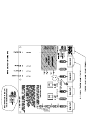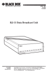
1
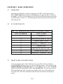
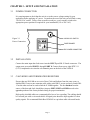
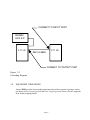
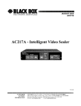
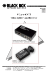
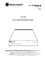
NOVEMBER 1998
MODEL:
TL576A
V.11 LS
(V.11 Data Broadcast Unit)
V.11 LS
POWER
DATA
CUSTOMER
SUPPORT
INFORMATION
CLOCK
INDICATE
To order or for technical support: Call 724-746-5500 or fax 724-746-0746
Technical support and fax orders 24 hours a day, 7 days a week.
Phone orders 24 hours, 7 A.M. Monday to midnight Friday; Saturday 8 to 4 (Eastern).
Mail order: Black Box Corporation, 1000 Park Drive, Lawrence, PA 15055-1018
Web site: http://www.blackbox.com · E-mail: [email protected]
SAFETY AND STANDARDS COMPLIANCE
U.S.A AND CANADIAN STANDARDS
FEDERAL COMMUNICATIONS COMMISSION
AND
CANADIAN DEPARTMENT OF COMMUNICATIONS
RADIO FREQUENCY INTERFERENCE STATEMENTS
This equipment generates, uses, and can radiate radio frequency energy and if not installed and
used properly, that is, in strict accordance with the manufacturer’s instructions, may cause
interference to radio communication. It has been tested and found to comply with the limits for a
Class A computing device in accordance with the specifications in Subpart J of Part 15 of FCC
rules, which are designed to provide reasonable protection against such interference when the
equipment is operated in a commercial environment. Operation of this equipment in a residential
area is likely to cause interference, in which case the user at his own expense will be required to
take whatever measures may be necessary to correct the interference.
Changes or modifications not expressly approved by the party responsible for compliance could
void the user’s authority to operate the equipment.
This digital apparatus does not exceed the Class A limits for radio noise emission from digital
apparatus set out in the Radio Interference Regulation of the Canadian Department of
Communications.
Le présent appareil numérique n’émet pas de bruits radioélectriques dépassant les limites
applicables aux appareils numériques de la classe A prescrites dans le Règlement sur le brouillage
radioélectrique publié par le ministère des Communications du Canada.
ELECTRICAL SAFETY STATEMENT - MEXICO
Normas Oficiales Mexicanas (NOM)
Electrical Safety Statement
INSTRUCCIONES DE SEGURIDAD
1. Todas las instrucciones de seguridad y operación deberán ser leídas antes de que el aparato
eléctrico sea operado.
2. Las instrucciones de seguridad y operación deberán ser guardadas para referencia futura.
3. Todas las advertencias en el aparato eléctrico y en sus instrucciones de operación deben ser
respetadas.
4. Todas las instrucciones de operación y uso deben ser seguidas.
5. El aparato eléctrico no deberá ser usado cerca del agua—por ejemplo, cerca de la tina de
baño, lavabo, sótano mojado o cerca de una alberca, etc.
6. El aparato eléctrico debe ser usado únicamente con carritos o pedestales que sean
recomendados por el fabricante.
7. El aparato eléctrico debe ser montado a la pared o al techo sólo como sea recomendado por
el fabricante.
8. Servicio—El usuario no debe intentar dar servicio al equipo eléctrico más allá a lo descrito
en las instrucciones de operación. Todo otro servicio deberá ser referido a personal de
servicio calificado.
9. El aparato eléctrico debe ser situado de tal manera que su posición no interfiera su uso. La
colocación del aparato eléctrico sobre una cama, sofá, alfombra o superficie similar puede
bloquea la ventilación, no se debe colocar en libreros o gabinetes que impidan el flujo de
aire por los orificios de ventilación.
10. El equipo eléctrico deber ser situado fuera del alcance de fuentes de calor como radiadores,
registros de calor, estufas u otros aparatos (incluyendo amplificadores) que producen calor.
11. El aparato eléctrico deberá ser connectado a una fuente de poder sólo del tipo descrito en el
instructivo de operación, o como se indique en el aparato.
12. Precaución debe ser tomada de tal manera que la tierra fisica y la polarización del equipo no
sea eliminada.
13. Los cables de la fuente de poder deben ser guiados de tal manera que no sean pisados ni
pellizcados por objetos colocados sobre o contra ellos, poniendo particular atención a los
contactos y receptáculos donde salen del aparato.
14. El equipo eléctrico debe ser limpiado únicamente de acuerdo a las recomendaciones del
fabricante.
15. En caso de existir, una antena externa deberá ser localizada lejos de las lineas de energia.
16. El cable de corriente deberá ser desconectado del cuando el equipo no sea usado por un
largo periodo de tiempo.
17. Cuidado debe ser tomado de tal manera que objectos liquidos no sean derramados sobre
la cubierta u orificios de ventilación.
18.
Servicio por personal calificado deberá ser provisto cuando:
A: El cable de poder o el contacto ha sido dañado; u
B: Objectos han caído o líquido ha sido derramado dentro del aparato; o
C: El aparato ha sido expuesto a la lluvia; o
D: El aparato parece no operar normalmente o muestra un cambio en su desempeño; o
E: El aparato ha sido tirado o su cubierta ha sido dañada.
TABLE OF CONTENTS
CHAPTER 1 - DESCRIPTION .................................................................................................... 1
1.1
FUNCTIONAL DESCRIPTION .......................................................................................... 1
CHAPTER 2 - BASIC OPERATION ........................................................................................... 2
2.1
OPERATION........................................................................................................................ 2
2.2
X.21 PORT PINOUTS ......................................................................................................... 2
2.3
FRONT PANEL LED INDICATORS ................................................................................. 2
CHAPTER 3 - SETUP AND INSTALLATION .......................................................................... 3
3.1
POWER CONNECTION ..................................................................................................... 3
3.2
INSTALLATION ................................................................................................................. 3
3.3
CASCADING AND TERMINATION RESISTORS .......................................................... 3
3.4
EQUIPMENT GROUNDING .............................................................................................. 3
APPENDIX A: ADDRESSES OF STANDARDS ORGANIZATIONS ................................... 5
APPENDIX B: TECHNICAL INFORMATION ........................................................................ 6
5.1
STRAPPING INFORMATION ........................................................................................... 6
5.2
TECHNICAL SPECIFICATIONS ....................................................................................... 7
i
CHAPTER 1 - DESCRIPTION
1.1
FUNCTIONAL DESCRIPTION
The V.11 LS is designed for use in receive only data broadcast applications. Examples of
typical data broadcast applications are: continuously updated private or public data displays and distribution of continuous data to PCs or receive only printers. The role of VSAT
systems in receive only applications for real time data distribution is expected to increase
dramatically over the next few years. The V.11 LS is an excellent choice for applications of
this type.
The V.11 LS utilizes an ITU V.11 (X.21) balanced interface with a maximum data rate of up
to 10Mbps. Additionally, V.11 can support data transmissions at far greater cable distances
than does RS-232. The V.11 LS can support an unlimited amount of receive only terminals
simultaneously.
The V.11 LS is housed in a sturdy aluminum enclosure and is supplied with an internal
linear power supply. The unit has a 110/220 VAC rotary select switch located on the rear of
the housing. The unit can operate on standard AC power found in all countries.
The V.11 LS's master port has tandem DB-15 connectors. This allows a dedicated input
port and an additional port for cascading without losing a sub-channel port. The V.11 LS
continuously broadcasts receive data, receive timing and Indicate (any user defined control
signal from the main input data source may be used). The input signals are split with the
internal circuitry and rebroadcast on the eight output ports.
HOST
ONE WAY DATA PATH TO TERMINALS
LEASED LINE
V.11 LS
TERMINAL
MODEM
MODEM
V.11 LS
Figure 1-1 Typical V.11 LS Application
Page 1
V.11 BALANCED
INTERFACE
SUPPORTS RS-422/449
V.35, RS-530, RS-485
AND X.21
CHAPTER 2 - BASIC OPERATION
2.1
OPERATION
Operation of the V.11 LS is as simple as plugging a male DB-15 cable into the female
DB-15 INPUT PORT on the back panel and plugging up to eight male DB-15 connectors
into Ports 1 - 8. Data, Clock and Indicate are received on the Master Port and are broadcast
out simultaneously on Ports 1 -8. The following table shows the pinout for the Master and
Sub-Channel Ports.
2.2
X.21 PORT PINOUTS
DB - 15 FEMALE OR MALE CO N N ECTORS
P IN NUMBER
P IN NAME
1
SHIELD
4
RECEIVE DATA (A+)
5
INDICATE (A+)
6
SIGN A L TIMING (A+)
8
GROUND
11
RECEIVE DATA (B-)
12
INDICATE (B-)
13
SIGN A L TIMING (B-)
2.3
FRONT PANEL LED INDICATORS
Located on the front panel of the V.11 LS are four green LEDs. The Power indicator,
marked POWER, illuminates when AC voltage is applied to the box. Three adjacent LED
indicatorsillum inate in conjunction w ith Receive Data (DATA), Receive Clock (CLOCK)
and the user defined control signal which is marked INDICATE. The DATA and CLOCK
LEDs will flash on and off at a constant rate regardless of the user’s clock and data rate.
The INDICATE LED will be illuminated when and if the user defined control signal is
present.
Page 2
CHAPTER 3 - SETUP AND INSTALLATION
3.1
POWER CONNECTION
It is very important to check that the unit is set to the correct voltage setting for your
application before applying AC power. Located on the rear of the unit you will find a rotary
110/220 VAC switch. Using a coin or small screwdriver, gently turn the switch to the
appropriate power position as required for your installation (110 or 220 VAC).
220
110
110/220 VAC SWITCH
Figure 3-1
Power Connection
FUSE DRAWER
IEC POWER CONNECTOR
3.2
INSTALLATION
Connect the main input data feed source into the INPUT port DB-15 female connector. The
output ports are marked PORT 1 through PORT 8. Connect from one to eight DTE V.11
(X.21) compliant devices into the sub-channels ports on the back of the V.11 LS.
3.3
CASCADING AND TERMINATION RESISTORS
If more than one V.11 LS are to receive Data, Clock and Indicate from the same source, a
shielded DB-15 one-to-one extension cable with a male DB-15 on one end and a female DB15 on the other end can be used to link the V.11 LS together. The box furthest from the
source of the data and clock should have jumpers JMP2, JMP3 and JMP4 moved to the
opposite position of the factory default setting for proper termination.
High quality shielded cables are recommended for box to box cascading. The cabling should
be a twisted pair with a wire mesh shield. All signal pairs should be kept together for clean
quality signals. We recommend Black Box EGM16E or equivalent cable with metal hoods.
Page 3
CONNECT TO "INPUT" PORT
MODEM
OR F.E.P.
V.11 LS
V.11 LS
DB-15 CABLE
CONNECT TO "OUTPUT" PORT
Figure 3-2
Cascading Diagram
3.4
EQUIPMENT GROUNDING
Jumper JMP1 provides for grounding interconnection in those systems requiring a connection between Pin #1 (frame ground) and Pin # 8 (signal ground). Please reference Appendix
B for further strapping details.
Page 4
APPENDIX A:
ADDRESSES OF STANDARDS ORGANIZATIONS
ANSI
American National Standards Institute
1430 Broadway
New York, NY 10018
Telephone: (212) 354-3300
ISO
Outside the United States
International Organization for Standardization
Central Secretariat
1 rue de Varembe
CH-1211 Geneva, Switzerland
Telephone +41 22 34-12-40
EIA
Electronic Industries Association
2001 Eye Street, N.W.
Washington, DC 20006
Telephone: (202) 457-4966
Inside the United States
American National Standards Institute
1430 Broadway
New York, NY 10018
Telephone: (212) 354-3300
FED-STD
General Services Administration
Specification Distribution Branch
Building 197
Washington Navy Yard
Washington, DC 20407
Telephone: (202) 472-1082
IEEE
The Institute of Electrical and
Electronics Engineers, Inc.
345 East 47th Street
New York, NY 10017
Telephone: (212) 705-7900
FIPS
U.S. Department of Commerce
National Technical Information Service
5285 Port Royal Road
Springfield, VA 22161
Telephone: (703) 487-4650
CCITT
Outside the United States
General Secretariat
International Telecommunications Union
Place des Nations
1121 Geneva 20, Switzerland
Telephone +41 22 995111
In the United States
United States Department of Commerce
National Technical Information Service
5285 Port Royal Road
Springfield, VA 22161
Telephone: (703) 487-4650
NBS
National Bureau of Standards
Institute for Computer Sciences
and Technology
Technology Building, Room B-253
Gaithersburg, MD 20899
Telephone: (301) 921-2731
CCITT documents may be reached by calling
(800) 553-6847
V.35 is a CCITT specification and is
implemented per ISO 2593
The ISO documents are obtainable by calling
(212) 354-3300
AT&T Bell Publications documents may be reached
by calling (800) 344-0223 or (800) 432-6600
Page 5
APPENDIX B
STRAPPING INFORMATION
Hold this space for the strapping chart
Page 6
5.2
TECHNICAL SPECIFICATIONS
Application
Multiple Synchronous broadcasting of Data,
Clock and Indicate utilizing V.11 signaling
Front Panel
Capacity
One to eight sub-channels:
Standard DB-15-S (female) interface
connector for each sub-channel
Power Requirement
Data Format
Data transparent at all data rates
Environmental
Data Rates
Up to 10 Mbps
Electrical Interface
ITU V.11 (Pinned to X.21)
Indicators.... Power, Data,
Clock and Indicate
100-120/200-220 VAC @+10%,
47 to 63 Hz, 5 Watts
Switch selectable
Operating Temperature....32º to 122º F
(0º to 50º C)
Relative Humidity.............5 to 90%
Non-Condensing
Altitude............................Up to 10,000 feet
(3048 meters)
Dimensions
Height ....... 1.75 inches
Width ........ 17.00 inches
Length ....... 9.00 inches
(4.44 cm)
(43.18 cm)
(22.86 cm)
Sub-Channel Interface
V.11, DB-15-S (female connectors)
Weight
4.5 pounds
Master Port
V.11, Female/Male DB-15 connectors
Enclosure
Metal: Aluminum
Approvals
UL 1950, FCC Class A
CE - EN60950
CE - EN55022
CE - EN50082-1
Shock and Vibration
Withstands normal shipping
Included With Each Unit:
Operations Manual
Grounded Power Cord
Page 7
(2.1Kg)
Copyright 1998. Black Box Corporation. All rights reserved
C
1000 Park Drive
i
Lawrence, PA 15055-1018
i
724-746-5500
i
Fax 724-746-0746