1
2 TON, 4 TON, 6 TON,
8 TON, 12 TON, 20 TON
BOTTLE JACK & 12 TON
AND 20 TON
SHORT BOTTLE JACKS
776-1037, 776-1038, 776-1039,
SETUP AND OPERATING INSTRUCTIONS
776-1040, 776-1041, 776-1042,
776-1021 and 776-1022
This is the safety alert symbol used for the SETUP and OPERATING INSTRUCTIONS section of this manual to alert you to potential personal injury hazards.
Obey all instructions to avoid possible injury or death.
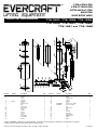
PLEASE REFER TO THE EXPLODED VIEW DRAWING IN THIS MANUAL IN ORDER TO IDENTIFY PARTS.
1.
2.
3.
4.
Assemble the pump handle sections together to make one complete handle. One end of the handle has a cut out that will fit over the cross pin in the release valve in the base of the jack. This connection enables the user to turn the release valve in a clockwise direction until tight in preparation for pumping the jack and raising the load. Slowly turning the release valve in a counterclockwise direction will lower the load. It is not necessary to open the release valve more than two full rotations.
The opposite end of the pump handle must be inserted in the pump piston receiver linkage in preparation for pumping the jack.
The ram is that part of the jack which extends when the jack is pumped. There is a round saddle at the end of the ram which is the part that makes contact with the
load to be lifted. The saddle is actually part of a threaded extension screw that fits on the inside of the ram. The saddle height can be extended by turning it in a counter
clockwise direction. Extending the height of the saddle is sometimes necessary when the full stroke of the ram is not adequate to lift a load to its desired work height.
Sometimes air gets trapped in the hydraulic system during shipment. An air bound hydraulic system feels spongy when pumped and may not allow the jack to pump full incremental strokes.
TO PURGE AIR FROM THE HYDRAULIC SYSTEM
a.
b.
c.
d.
e.
Open the release valve by turning the handle in a counterclockwise direction two full turns from its closed position.
Pump the handle ten full strokes.
Close the release valve by turning the handle in a clockwise direction until tight.
Pump the jack until the ram is extended to maximum height.
If the condition seems better but is still detectable, repeat steps "a" through "d" until all the air is purged from the system.
5. Do not lift more than one wheel of a vehicle at a time. Activate the hazard warning flasher, turn off ignition, move automatic selector to park position or reverse gear if it is a
manual transmission and set parking brake. The wheel diagonally opposite from the wheel being lifted shall be chocked in both directions. Consult the vehicle manufacturer for the tire changing procedure and lift points.
6. Position the jack at the appropriate lift point. Estimate the required ram travel to raise the load to the desired height. If the desired height exceeds the entire ram travel, unscrew the extension screw to make up the difference.
7. Pump the jack up until the saddle comes close to the lift point. Make sure the lift point is flat, parallel to the ground and free from grease, any kind of lubricant, or debris. Continue pumping the jack to lift the load to the desired height. During lifting, inspect the position of the jack in relation to the ground and the saddle in relation to the load to prevent any unstable conditions from developing. If conditions look like they are becoming unstable, slowly lower the load and make
appropriate setup corrections after the load is fully lowered.
8. When the load is lifted to its desired height, immediately place jack stands in their designated locations and adjust the stands' support columns up as close to the
designated supports points as possible. Although jack stands are individually rated, they are to be used in a matched pair to support the load. Slowly and carefully open the release valve of the jack in order to gently lower the load onto the jack stands. Make sure the load is safety supported by the jack stands' saddles and not the locating lugs of the saddles. Inspect the relationship of the jack stands with the ground and the jack stand columns and saddles with the load to prevent any unstable conditions. If
conditions look unstable, close the jack's release valve and pump the jack to raise the load off the jack stands. Make the appropriate setup changes and slowly and carefully
lower the load onto the jack stand saddles.
9. After the work is done, close the release valve and pump the jack high enough to remove the load from the jack stand saddles. Be sure the load is stable. If it is not,
lower the load back onto the jack stands. Make appropriate setup corrections and repeat the step again. Remove the jack stands from under the load, being very careful not
to move the load.
10. Open the jack's release valve very slowly and carefully to lower the load to the ground.
PREVENTATIVE MAINTENANCE
This is the safety alert symbol used for the PREVENTATIVE MAINTENANCE section of this manual to alert you to potential personal injury hazards.
Obey all instructions to avoid possible injury or death.
IMPORTANT: Any jack found to be defective as a result of worn parts due to lack of lubrication, or air/hydraulic system contaminated with water, rust and/or foreign materials from the air supply or other outside source is not eligible for warranty consideration.
1. Always store the jack in a well protected area where it will not be exposed to inclement weather, corrosive vapors, abrasive dust, or any other harmful elements.
The jack must be cleaned of water, snow, sand or grit before using.
776-1037, 776-1038, 776-1039, 776-1040, 776-1041, 776-1042, 776-1021, 776-1022 2
rev. 09/21/11