Download KN 8055 - KNOVA

Transcript
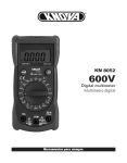
KN 8055
600V
Digital automotive
multimeter
Multímetro digital automotriz
KNOVA
TABLE OF CONTENTS
1. SAFETY INFORMATION
1.1 PRELIMINARY
1.2 DURING USE
1.3 SYMBOLS
1.4 MAINTENANCE 1
2
3
5
7
2. DESCRIPTION
2.1 NAMES OF COMPONENTS
2.2 SWITCH, BUTTONS AND INPUT JACK ELUCIDATION 8
9
9
3. SPECIFICATIONS
3.1 GENERAL SPECIFICATIONS
3.2 ELECTRICAL SPECIFICATIONS
12
12
14
4. OPERATING INSTRUCTION
4.1 POWER-UP
4.2 DATA HOLD
4.3 MAXIMUM VALUE HOLD
4.4 FUNCTION TRANSFORM
4.5 RANGE TRANSFORM
4.6 BACK LIGHT
4.7 AUTO WARNING 4.8 AUTO POWER OFF
4.9 PREPARATION FOR MEASUREMENT
4.10 MEASURING DC VOLTAGE
4.11 MEASURING AC VOLTAGE
4.12 MEASURING DC CURRENT
4.13DC CURRENT MEASURING
(WITH CLAMP, OPTIONAL)
4.14MEASURING AC CURRENT
4.15AC CURRENT MEASURING
(WITH CLAMP, OPTIONAL)
4.16MEASURING RESISTANCE
4.17MEASURING TEMPERATURE ℃
4.18MEASURING TEMPERATURE ℉
4.19MEASURING ENGINE DWELL
4.20MEASURING ENGINE REV
4.21DIODE TESTING
4.22CONTINUITY TESTING
22
22
22
22
22
23
24
25
25
26
27
33
35
43
45
47
49
51
53
55
57
5. MAINTENANCE
5.1 BATTERY REPLACEMENT
5.2 TEST LEADS REPLACEMENT
59
59
60
6. ACCESSORIES
60
38
41
1. SAFETY INFORMATION
!
WARNING
To ensure safe operation, and in order to exploit to the full the functionality of the meter, please follow the instructions in
this section carefully.
This multimeter has been designed according to IEC-1010 concerning
electronic measuring instruments with an overvoltage category CAT ΙΙΙ
600V and pollution 2.
Follow all safety and operation instructions to ensure that the meter is
used safely and is kept in good operating condition.
With proper use and care, the digital meter will give you years of
satisfactory service.
1
KNOVA
1.1 PRELIMINARY
1.1.1 When using the meter, the user must observe all normal safety
rules concerning:
• Protection against the dangers of electrical current.
• Protection of the meter against misuse.
1.1.2 When the meter is delivered, check that it has not been damaged
in transit.
1.1.3 When poor condition under harsh preservation or shipping
conditions caused, inspect and confirm this meter without delay.
1.1.4 Test leads must be in good condition. Before using, verify that
the insulation on test leads is not damaged and/or the leads wire is not
exposed.
1.1.5 Full compliance with safety standards can be guaranteed only if
used with test leads supplied. If necessary, they must be replaced with
the same model or same electric ratings.
2
1.2 DURING USE
1.2.1 Before using, you must select the right input jack, function and
range.
1.2.2 Never exceed the protection limit values indicated in the
specifications for each range of measurement.
1.2.3 When the meter is linked to a measurement circuit, do not touch
unused terminals.
1.2.4 At the manual range, when the value scale to be measured is
unknown beforehand, set the range selector at the highest position.
1.2.5 Do not measure voltage if the voltage on the terminals exceeds
600V above earth ground.
1.2.6 Always be careful when working with voltages above 60V DC or
30V AC rms, keep fingers behind the probe barriers while measuring.
3
KNOVA
1.2.7 Never connect the meter leads across a voltage source while the
transform switch is in the current, resistance, temperature, diode or
continuity mode. Doing so can damage the meter.
1.2.8 Before rotating the transform switch to change functions and
ranges, disconnect test leads from the circuit under test.
1.2.9 Never perform resistance, temperature, diode and continuity
measurements on live circuits.
1.2.10 Never use the meter under the condition of explosive air, steam
or dirt.
1.2.11 If any faults or abnormalities are observed, the meter can not be
used any more and it has to be checked out.
1.2.12 Never use the meter unless the rear case is in place and fastened
fully.
4
1.2.13 Please do not store or use the meter in areas exposed to direct
sunlight, high temperatures, humidity or condensation.
1.3 SYMBOLS
Important safety information, refer to the operating manual.
Double insulation Protection classΙΙ.
CAT III Overvoltage (Installation) category III, Pollution Degree 2 per IEC1010-1 refers to the level of Impulse Withstand Voltage protec
tion provided.
Conforms to European Union directive
Earth ground
AC Alternating current
DCDirect current
Diode
Continuity buzzer
5
KNOVA
~AC or DC (alternating current or direct current)
Engine dwell
RPM Round per minute
10 Reading multiplies 10
Measurement with clamp (optional), widening the field of
applications of the meter
℃ Centigrade
℉ Fahrenheit
MAX-H The maximum value is being held.
DATA-H This indicates that the display data is being held.
AUTO Auto range
+
-
The battery is not sufficient for proper operation.
6
1.4 MAINTENANCE
1.4.1 Please do not attempt to adjust or repair the meter by removing
the rear case while voltage is being applied. Only a technician who fully
understands the dangers involved should carry out such actions.
1.4.2 Before opening the battery cover or case of the meter, always
disconnect test leads from all tested circuits.
1.4.3 To avoid the wrong reading causing electricity shock, when the
meter displays “ + - ”, you must change the battery.
1.4.4 Do not use abrasives or solvents on the meter, use a damp cloth
and mild detergent only.
1.4.5 Always set the power switch to the OFF position when the meter is
not in use.
1.4.6 If the meter is to be stored for a long period of time, the batteries
should be removed to prevent damage to the unit.
7
KNOVA
2. DESCRIPTION
- This meter is a portable professional measuring tool with handsome LCD and back light for easy reading.
- Single operation of a transform switch makes measurement convenient. Overload protection and low battery indication are provided, this meter is ideal for use in the field, workshop, school, hobby and home
applications.
- This meter has auto range and manual range functions.
- This meter has an auto warning function.
- This meter has an auto power off function.
- This meter also has data hold and maximum value hold functions.
- When being used, it can show ranges engineering unit enunciators measuring results.
8
2.1 NAMES OF COMPONENTS
(1) LCD Display
(2) ON/OFF Button
(3) RANGE Button
(4) FUNC. Button
(5) Transform Switch
(6)
10A Jack
(7) INPUT Jack
(8) COM Jack
(9) Panel
(10)
Button
(11) DATA-H Button
(12) MAX.H Button
~
2.2 SWITCH, BUTTONS AND INPUT JACK ELUCIDATION
• ON/OFF Button
This Button is used to turn power on and off.
9
KNOVA
1
12
2
11
3
10
9
4
5
8
6
7
10
• RANGE Button
This button is used to turn from Auto range to manual range.
• FUNC. Button
This button is used to switch functions.
• DATA-H Button
This Button is used to turn on data hold.
• MAX.H Button
This Button is used to turn on maximum value hold.
•
Button
This button is used to turn on back light.
• Transform Switch
This switch is used to select functions and desired ranges.
• 10A Jack
Input terminal for current 0 ~ 10A.
• INPUT Jack
Input terminals except A
• COM Jack
Common terminal for measurement
11
KNOVA
3. SPECIFICATIONS
Accuracy is specified for a period of year after calibration and at 18℃ to
28℃ 64°F to 82°Fwith a relative humidity of 75% max.
3.1 GENERAL SPECIFICATIONS
3.1.1 Auto ranges and manual range.
3.1.2 Over range protection for all ranges.
3.1.3 Max. Voltage Between Terminals And Earth Ground:
600V DC or AC
3.1.4 Operating Altitude: 2000 meters (7000 ft.) maximum
3.1.5 Display: 16mm LCD
3.1.6 Max. Show Value: 1999 (3 1/2)
3.1.7 Polarity Indication: “-”indicates negative polarity.
3.1.8 Over range Indication: Display “OL”
3.1.9 Sampling Time: approx. 0.4 second
3.1.10 Unit showing: showing of function and electrical capacity.
12
3.1.11 Low Battery Indication: “
+ -
” displayed
3.1.12 Auto power off time: 15 min.
3.1.13 Power Supply: 1.5V 3 AAA battery.
3.1.14 Operating Temperature: 0℃ to 40℃ 32°F to 104°F
3.1.15 Storage Temperature: -10℃ to 50℃ 10°F to 122°F
3.1.16 Dimensions: 158 74 32 mm
3.1.17 Weight: approx. 250g including battery
13
KNOVA
3.2 ELECTRICAL SPECIFICATIONS
Circumstance Temperature: 23±5℃
Relative Humidity: < 75%
3.2.1 DC Voltage
Range
Resolution
200mV
0.1mV
2V
0.001V
20V
0.01V
200V
0.1V
600V
1V
Accuracy
± (0.7% of
rdg + 2 digits)
- Input Impedance: 10MΩ
- Overload Protection:
200mV range: 250V DC or AC rms, 2V-600V ranges:
600V DC or AC rms.
- Max. Input Voltage: 600V DC
14
3.2.2 AC Voltage
Range
Resolution
200mV
0.1mV
2V
0.001V
20V
0.01V
200V
0.1V
600V
1V
Accuracy
±(0.8% of rdg + 3 digits)
±(1.0% of rdg + 3 digits)
- Input Impedance: 10MΩ
- Overload Protection:
200mV range: 250V DC or AC rms, 2V-600V ranges:
600V DC or AC rms.
- Frequency Range: 40 to 400Hz
- Response: Average, calibrated in rms of sine wave.
- Max. Input Voltage: 600V rms AC
3.2.3 DC Current
Range
Resolution
2.000A
0.001A
10.00A
0.01A
Accuracy
±(2.0% of rdg + 10 digits)
15
KNOVA
- Overload Protection: unfused.
- Max. Input Current: 10A
- Voltage drop: 2A range: 20mV,
10A range: 200mV
3.2.4 AC Current
Range
Resolution
2.000A
0.001A
10.00A
0.01A
Accuracy
±(3.0% of rdg + 10 digits)
- Overload Protection: unfused.
- Max. Input Current: 10A
- Frequency Range: 40 to 400Hz
- Response: Average, calibrated in rms of sine wave.
- Voltage drop: 2A range: 20mV,
10A range: 200mV
16
3.2.5 DC Current (with clamp, optional)
Range
Resolution
Accuracy
meter
200A
0.1mV
/0.1A
±(1.2 % of rdg + 3 digits)
(DC)
Clamp
0 to 200A
/0.1A
0.1mV
Typical ±(2.0 %)
meter
2000A
0.1mV/1A
±(1.2 % of rdg + 3 digits)
(DC)
Clamp
0 to 2000A
1A /1mV
Typical ±(2.0 %)
- Overload Protection: 250V DC or 250V rms AC.
- Max. Input Voltage: 200mV
17
KNOVA
3.2.6 AC Current (with clamp, optional)
Range
Resolution
Accuracy
meter
200A
0.1mV
/0.1A
±(1.5 % of rdg + 5 digits)
(DC)
Clamp
0 to 200A
0.1A
/0.1mV
Typical ±(3.0 %)
meter
2000A
1mV/1A
±(1.5 % of rdg + 5 digits)
(DC)
Clamp
0 to 2000A
1A /1mV
Typical ±(3.0 %)
- Overload Protection: 250V DC or 250V rms AC.
- Max. Input Voltage: 200mV
- Frequency Range: 40 to 400Hz
- Response: Average, calibrated in rms of sine wave.
18
3.2.7 Resistance
Range
Resolution
Accuracy
200Ω
0.1Ω
±(1.0% of rdg + 3 digits)
2kΩ
0.001kΩ
±(1.0% of rdg + 1 digit)
20kΩ
0.01kΩ
±(1.0% of rdg + 1 digit)
200kΩ
0.1kΩ
±(1.0% of rdg + 1 digit)
2MΩ
0.001MΩ
±(1.0% of rdg + 1 digit)
20MΩ
0.01MΩ
±(1.0% of rdg + 5 digits)
- Open Circuit Voltage: 0.25V
- Overload Protection: 250V DC or 250V rms AC
3.2.8 Continuity
Range
Function
Built-in buzzer will sound, if resistance is lower than 50Ω.
- Open circuit voltage: approx. 0.5V
- Overload Protection: 250V DC or 250V rms AC
19
KNOVA
3.2.9 Temperature
-20℃ to 1000℃
Range
Resolution
Accuracy
1℃
-20℃ to 0℃
±(5% of rdg + 4digits)
0℃ to 400℃
±(1% of rdg + 3digits)
400℃ to 1000℃
±(2% of rdg + 3digits)
Range
-0℉ to 1800℉
Resolution
Accuracy
1℉
-0℉~50℉
±(5% of rdg + 4digits)
50℉~750℉
±(1% of rdg + 3digits)
750℉~1800℉
±(2% of rdg + 3digits)
- Overload Protection: 250V DC or rms AC
3.2.9 Temperature
Range
Resolution
Accuracy
4CYL
0.1º
±(3º)
6CYL
0.1º
±(3º)
8CYL
0.1º
±(3º)
- Overload Protection: 250V DC or rms AC
20
3.2.11 Engine Rev
Range
Resolution
4CYL
10RPM
6CYL
10RPM
8CYL
10RPM
Accuracy
±(3.0% of rdg + 3 digits)
- Overload Protection: 250V DC or rms AC
3.2.12 Diode
Range
Function
1mV
Display :read approximate forward voltage of diode
- Forward DC Current: approx. 1mA
- Reversed DC Voltage: approx.1.5V
- Overload Protection: 250V DC or rms AC
21
KNOVA
4. OPERATING INSTRUCTION
4.1 POWER-UP
Press the “ON/OFF” button to turn the meter ON or OFF.
4.2 DATA HOLD
If you need data hold when measuring, press the “DATA-H” button, it will
hold the reading; if you press the button again, data hold is stopped.
4.3 MAXIMUM VALUE HOLD
If you need data hold when measuring, press the “MAX.H” button, it will
hold the maximum value; if you press the button again, maximum value
hold is stopped.
4.4 FUNCTION TRANSFORM
Pressing “FUNC.” when measuring the current and voltage, Meter will
switch between DC and AC range.
22
Pressing “FUNC.” when measuring the temperature, meter will switch
between ℃ and ℉ range. Pressing “FUNC.” when measuring the diode
and continuity, meter will switch among them.
4.5 RANGE TRANSFORM
The auto range is used when measuring the current, voltage and
resistance. Press “RANGE” if the manual range is needed. Each time
you press it, range will go upward; the minimum range is changed if
“RANGE” is pressed at the maximum range. If “RANGE” is pressed
more than two seconds, auto range comes back.
23
KNOVA
4.6 BACK LIGHT
If the light is dark to make the reading difficult when measuring, you
can press the “ ” button to turn on the back light, which will last for 15
seconds. Continuous pressing the button for two seconds will turn off the
back light.
NOTE:
• LED is the main source of the back light. Its working current is
large, although the meter has a timer (it will turn off automatically
after 15 seconds); often use of back light will shorten the battery life, you’d better not use the back light so frequently if it’s not necessary.
• When the battery voltage is less than 3.8V, it will show “ ++-- ”.
But if you use the back light at the same time, maybe “ + - ” will
come up even if the battery voltage is more than 3.8V, because the working
24
current is higher and the voltage will decline. (When “ + - ” shows, the
accuracy of the measurement can not be assured.) You need not replace
the battery. When you use it normally (back light is not using), “ + - ” will
not show up. You will need to replace it till “ + - ”shows again.
4.7 AUTO WARNING
If the input voltage is larger than 2V at the
range and if the input current is larger than 10A, the buzzer will have a long sound.
4.8 AUTO POWER OFF
• If there’s no operation within fifteen minutes after power is on, meter
will auto power off with five short sounds and a long sound in a minute.
• After auto power off, if the transform switch is touched or the buttons
“FUNC.”, “DATA-H”, ”MAX.H”, ”RANGE” are pressed, the meter will
turn back on.
25
KNOVA
• If the “FUNC” button is pressed when power is on, auto power off will
disable.
4.9 PREPARATION FOR MEASUREMENT
4.9.1 Press the “ON/OFF” button. If the battery voltage is less than
3.8V, display will show “ + - ”, the battery should be changed at this
time.
4.9.2 The “ ” next to the input jack shows that the input voltage or
current should be less than specification on the sticker of the meter to
protect the inner circuit from damaging.
4.9.3 Select a function and a range for the item to be measured through
rotating the transform switch accordingly. When the value scale to be
measured is unknown beforehand, set the range selector at the highest
position.
4.9.4 When connecting, first connect to the public testing line, then to
the electrical testing line. When you remove it, you should remove the
electrical one.
26
4.10 MEASURING DC VOLTAGE
!
WARNING
You can’t input the voltage with more than 600V DC, it’s
possible to show higher voltage, but it may destroy the inner cir
cuit. Pay attention not to get an electric shock when measuring high voltage.
4.10.1 Connect the black test lead to the COM jack and the red test lead
to the INPUT jack.
4.10.2 Set the transform switch at the V range position.
4.10.3 Press “FUNC.” to enter the DC measurement. Auto range or
manual range can be chosen by pressing “RANGE”.
27
KNOVA
28
4.10.4 Connect test leads across the source or load under measurement.
4.10.5 You can get a reading from the LCD display. The polarity of the
red test lead connection will be indicated.
NOTE:
• At a little voltage range, the meter will show unsteady reading when test leads haven’t reached the circuit. This is normal because the me
ter is very sensitive. When test leads touch the circuit, you can get
a true reading.
• At the manual range mode, when only the figure ‘OL’ is displayed,
it indicates over range situation and a higher range has to be selected.
• At the manual range mode, when the value scale to be measured is unknown beforehand, set the range selector at the highest position.
29
KNOVA
Application 1: Use 2V range to test the end state of the divider.
A.Take the high voltage line away from the cover of the divider, then
connect with the iron.
B.The red test lead is connected to the low voltage connection pole of
the divider, or to the end “-”of the ignition winding; the black test leads is
connected to the iron or the negative pole of the storage cell.
C.Open the ignition switch a little, the meter will indicate the value lower
than 1V.
D.Directly measure the voltage of the end’s both sides, the end is good if
the value indicated is less than 0.2V.
Application 2: Use 2V range to check the leakage of the
storage cell.
A.The black test lead is connected to the iron or the pole “-”, the red one
is connected to all ends of the storage cell.
30
B.If some value is indicated on the meter, there is leakage. The storage
cell should be cleaned or replaced.
Application 3: Use 20V range to check the load capability of the
storage cell.
A.The black test lead is connected to the iron or the negative pole of the
storage cell; the red one to the positive pole of the cell.
B.Open the switch of the front light, of the flashing, of the ignition and of
the radio respectively.
C.The above process should be finished in 2 minutes.
D.Check if the value is less than 11.7V, if it is, then the storage cell
should be recharged or replaced.
31
KNOVA
Application 4: Use 20V range to check the capability of the
storage cell.
A.Take the high voltage line away from the cover of the divider and
connect to the iron.
B.The black test lead is connected to the iron or the negative pole of the
storage cell, and the red one to its positive pole.
C.Start the engine and 15 seconds later check if the indicating value is
over 9.1V; if it is not correct, the engine should be checked or the storage
cell should be recharged or replaced.
Application 5: Check the cable of the power supply.
While the engine is on, measure the voltage of the both sides of the
cable.
32
4.11 MEASURING AC VOLTAGE
!
WARNING
You can’t input a voltage over 600V rms AC, it’s possible to show higher voltage, but it may destroy the inner circuit.
Pay attention not to get an electric shock when measuring voltage.
4.11.1 Connect the black test lead to the COM jack and the red test lead
to the INPUT jack.
4.11.2 Set the transform switch at the V range position.
4.11.3 Press “FUNC.” to enter the AC measurement. Auto range or
manual range can be transformed by pressing “RANGE”.
4.11.4 Connect test leads across the source or load under measurement.
4.11.5 You can get reading from LCD.
33
KNOVA
34
NOTE:
• At low voltage range, the meter will show unsteady reading when test leads haven’t reach the circuit. This is normal because the meter is very sensitive. When test leads touch the circuit, you can get a true reading.
• At the manual range mode, when only the figure ‘OL’ is dis
played, it indicates over range situation and a higher range has to be selected.
• At the manual range mode, when the value scale to be measured is unknown beforehand, set the range selector at the highest
position.
4.12 MEASURING DC CURRENT
!
WARNING
Shut down the power of the tested circuit, then connect the meter to the circuit for measurement.
35
KNOVA
36
4.12.1 Connect the black test lead to the COM jack and the red test lead
to the 10A jack.
4.12.2 Set the transform switch at the A range position.
4.12.3 Press “FUNC.” to enter the DC measurement. Auto range or
manual range can be transformed by pressing “RANGE”.
4.12.4 Connect test leads in series with the load under measurement.
4.12.5 You can get reading from LCD. The polarity of red test lead will
be indicated.
NOTE:
• When only the figure ‘OL’ is displayed, it indicates over range situation and a higher range has to be selected.
• When the value scale to be measured is unknown beforehand, set the range selector at the highest position.
• “ ” means the socket of 10A jack maximum current is 10A, no fuse protection.
37
KNOVA
4.13 DC CURRENT MEASURING
(WITH CLAMP, OPTIONAL)
4.13.1 Connect the black output lead of clamp to the COM jack and the
red one to the INPUT jack of the meter.
4.13.2 Set the transform switch at the”
” range position.
4.13.3 Press “FUNC.” to enter the DC measurement. Auto range or
manual range can be transformed by pressing “RANGE”.
4.13.4 Clamp the circuit under measured.
4.13.5 You can get reading from LCD. The polarity of red output lead will
be indicated.
NOTE:
• At the manual range mode, when only the figure ‘OL’ is displayed,
it indicates over range situation and the higher range has to be
selected.
38
39
KNOVA
• At the manual range mode, when the value scale to be measured is unknown beforehand, set the range selector at the highest position.
• Select the DC clamp to measure the DC current.
• Matching problem about the meter and the sensitivity of the clamp:
a. The sensitivity of 200A range is 200mV, that of 2000A is 2V; the sen
sitivity of the matching clamp is 0.1A/0.1mV. The present indicated value is the same as the measured value.
b. If the sensitivity of the selected clamp is low (0.1A/0.01mV), the
indicated value will be 10 times lower than the measured value. For example, the measured current is 100A, then the indicated value will be 10.0A.
c. If the sensitivity of the selected clamp is high (0.1A/1mV), the
indicated value will be 10 times higher than the measured value. For example, the measured current is 100A, then the indicated value will be 1000A.
40
4.14 MEASURING AC CURRENT
!
WARNING
Shut down the power of the tested circuit, then connect
the meter to the circuit for measurement.
4.14.1 Connect the black test lead to the COM jack and the red test lead
to the 10A jack.
4.14.2 Set the transform switch at the A range position.
4.14.3 Press “FUNC.” to enter the AC measurement. Auto range or
manual range can be transformed by pressing “RANGE”.
4.14.4 Connect test leads in series with the load under measurement.
4.14.5 You can get reading from LCD.
NOTE:
• When only the figure ‘OL’ is displayed, it indicates over range
situation and the higher range has to be selected.
• When the value scale to be measured is unknown beforehand, set the range selector at the highest position.
• “ ” means the socket of 10A jack maximum current is 10A,
no fuse protection.
41
KNOVA
42
4.15 AC CURRENT MEASURING
(WITH CLAMP, OPTIONAL)
4.15.1 Connect the black output lead of clamp to the COM jack and the
red one to the INPUT jack of the meter.
4.15.2 Set the transform switch at the “
” range position.
4.15.3 Press “FUNC.” to enter the AC measurement. Auto range or
manual range can be transformed by pressing “RANGE”.
4.15.4 Clamp the circuit under measured.
4.15.5 You can get reading from LCD.
NOTE:
• At the manual range mode, when only the figure ‘OL’ is displayed, it indicates over range situation and a higher range has to be selected.
• At the manual range mode, when the value scale to be measured is unknown beforehand, set the range selector at the highest position.
• Select the AC clamp to measure the AC current.
• Matching problem about the meter and the sensitivity of the clamp:
a. The sensitivity of 200A range is 200mV, that of 2000A is 2V; the sensitivity of the matching clamp is 0.1A/0.1mV. The present indicated value is same to the measured value.
b. If the sensitivity of the selected clamp is low (0.1A/0.01mV),
the indicated value will be 10 times lower than the measured value. For example, the measured current is 100A, then the indicated value will be 10.0A.
c. If the sensitivity of the selected clamp is high (0.1A/1mV), the
indicated value will be 10 times higher than the measured value. For example, the measured current is 100A, then the indicated value will be 1000A.
43
KNOVA
44
4.16 MEASURING RESISTANCE
!
WARNING
When measuring in-circuit resistance, be sure the circuit under test has all power removed and that all capacitors have been discharged fully.
4.16.1 Connect the black test lead to the COM jack and the red test lead
to the INPUT jack.
4.16.2 Set the transform switch at the Ω range position. Auto range or
manual range can be transformed by pressing “RANGE”.
4.16.3 Connect test leads across the resistance under measurement.
4.16.4 You can get reading from LCD.
NOTE:
• At the manual range mode, when only the figure ‘OL’ is displayed,
it indicates over range situation and the higher range has to be se
lected.
• For measuring resistance above 1MΩ, the meter may take a few
seconds to get stable reading.
• When the input is not connected, i.e. at open circuit, the figure ‘1’
will be displayed for the over range condition.
45
KNOVA
46
4.17 MEASURING TEMPERATURE ℃
!
WARNING
To avoid electrical shock, do not connect the thermocouples with the electrical circuit.
4.17.1 Set the transform switch at the TEMP range position.
4.17.2 Press “FUNC.” to enter the ℃ measurement.
4.17.3 The LCD display will show the current environment temperature.
4.17.4 When measuring the temperature with thermocouple, ‘K’ type
probe for this meter can be used. Insert the black plug to the COM jack
and the red one to the INPUT jack, touch the end of the temperature
sensor to the area or surface of the object for measurement.
4.17.5 You can get reading from LCD.
NOTE:
• With better sealing, the meter’s temperature measured circuit and environment need a little longer time to reach heat balance, and then accurate reading can be obtained.
47
KNOVA
48
4.18 MEASURING TEMPERATURE ℉
!
WARNING
To avoid electrical shock, do not connect the thermocouples to the electrical circuit.
4.18.1 Set the transform switch at the TEMP range position.
4.18.2 Press “FUNC.” to enter the ℉ measurement.
4.18.3 The LCD display will show the current environment temperature.
4.18.4 When measuring the temperature with thermocouple, ‘K’ type
probe for this meter can be used. Insert the black plug to the COM jack
and the red one to the INPUT jack, touch the end of the temperature
sensor with the area or surface of the object for measurement.
4.18.5 You can get reading from LCD.
NOTE:
• With better sealing, the meter’s temperature measured circuit and environment need a little longer time to reach heat balance, and then
accurate reading can be obtained.
49
KNOVA
50
4.19 MEASURING ENGINE DWELL
4.19.1 Connect the black test lead to the COM jack and the red test
lead to the INPUT jack.
4.19.2 Set the transform switch at the desired DWELL range position
according to the measured cylinder of the engine.
4.19.3 Connect the black test lead to the iron or the negative pole of the
storage cell, and the red one to the low voltage connection pole of the
divider or the negative pole of the ignition winding for measurement.
4.19.4 You can get reading from LCD after the engine is started.
51
KNOVA
storage
battery
ignition
switch
spark plug
distributor
52
ignition
winding
4.20 MEASURING REV
4.20.1 Connect the black test lead to the COM jack and the red test lead
to the INPUT jack.
4.20.2 Set the transform switch at the desired TACH range position
according to the measured cylinder of the engine.
4.20.3 Connect the black test lead to the iron or the negative pole of the
storage cell, and the red one to the low voltage connection pole of the
divider or the negative pole of the ignition winding for measurement.
4.20.4 You can get reading from LCD after the engine is started.
53
KNOVA
storage
battery
ignition
switch
spark plug
distributor
54
ignition
winding
4.21 TESTING DIODE
4.21.1 Connect the black test lead to the COM jack and the red test lead
to the INPUT jack. (The polarity of red lead is “+”)
4.21.2 Set the transform switch at the
range position.
4.21.3 Press “FUNC.” transformed at
test.
4.21.4 Connect the red lead to the anode, the black lead to the cathode
of the diode under testing.
4.21.5 You can get reading from LCD.
NOTE:
• The meter will show the approximate forward voltage drop of
the diode.
• If the lead connection is reversed, only figure ‘OL’ will be displayed.
• When the input is not connected, i.e. at open circuit, the figure ‘OL’
will be displayed.
55
KNOVA
56
4.22 CONTINUITY TEST
!
WARNING
When testing the circuit continuity, be sure that the power
of the circuit has been shut down and all capacitors have been
discharged fully.
4.22.1 Connect the black test lead to the COM jack and the red test lead
to the INPUT jack.
4.22.2 Set the transform switch at the
range position.
4.22.3 Press “FUNC.” transformed at
continuity test.
4.22.4 Connect test leads across two points of the circuit under testing.
4.22.5 If continuity exists (i.e., resistance less than about 50Ω), the
built-in buzzer will sound.
NOTE:
• If the input open circuit (or the circuit resistance measured is higher than 200Ω), then the figure ’0L’ will be displayed.
57
KNOVA
58
5. MAINTENANCE
!
WARNING
Before attempting to open the battery cover or case of the
meter, be sure that test leads have been disconnected from
measurement circuit to avoid electric shock hazards.
5.1 BATTERY REPLACEMENT
!
WARNING
Before attempting to open the battery cover of the meter,
be sure that test leads have been disconnected from measurement circuit to avoid electric shock hazards.
5.1.1 If the sign “ + - ”appears on the LCD display, it indicates that the
battery should be replaced.
5.1.2 Loosen the screw fixing the battery
59
KNOVA
5.1.3 Replace the old battery with a new one.
5.1.4 Put the battery cover back.
5.2 TEST LEADS REPLACEMENT
!
WARNING
Full compliance with safety standards can be guaranteed
only if the tool is used with test leads supplied. If necessary, they
must be replaced with the same model or same electric ratings.
Electric ratings of the test leads: 1000V 10A.
You must replaced the test leads if the lead is exposed.
6. ACCESSORIES
•Test Leads: Electric Ratings 1000V 10A
•Battery: 1.5V, AAA
•Operating Manual
•Thermocouple (K type)
60
one part
three parts
one part
one part
CONTENIDOS
1. INFORMACIÓN DE SEGURIDAD
1.1 OPERACIONES PRELIMINARES
1.2 DURANTE EL USO
1.3 SÍMBOLOS
1.4 MANTENIMIENTO 1
2
3
5
7
2. DESCRIPCIÓN
2.1 NOMBRES DE LOS COMPONENTES
2.2 INFORMACIÓN SOBRE INTERRUPTOR, BOTONES
Y CONECTOR DE ENTRADA 8
9
11
3. ESPECIFICACIONES
3.1 ESPECIFICACIONES GENERALES
3.2 ESPECIFICACIONES ELÉCTRICAS
12
12
14
4. INSTRUCCIONES DE OPERACIÓN
4.1 ENCENDIDO
4.2 RETENCIÓN DE DATOS
4.3 RETENCIÓN DE VALOR MÁXIMO
4.4 TRANSFORMACIÓN DE FUNCIONES
4.5 TRANSFORMACIÓN DE ESCALA
4.6 LUZ DE FONDO
4.7 ADVERTENCIA AUTOMÁTICA 4.8 APAGADO AUTOMÁTICO
4.9 PREPARACIÓN PARA LA MEDICIÓN
4.10 MEDIR EL VOLTAJE CD
4.11 MEDIR EL VOLTAJE CA
4.12 MEDIR LA CORRIENTE CD
4.13 MEDIR LA CORRIENTE CD
(CON ABRAZADERA, OPCIONAL)
4.14 MEDIR LA CORRIENTE CA
4.15 MEDIR LA CORRIENTE CA (CON ABRAZADERA, OPCIONAL) 4.16 MEDIR LA RESISTENCIA
4.17 MEDIR LA TEMPERATURA (°C)
4.18 MEDIR LA TEMPERATURA ( °F ) 4.19 MEDIR EL ÁNGULO DEL MOTOR
4.20 MEDIR LAS REVOLUCIONES DEL MOTOR
4.21 PRUEBA DE DIODOS
4.22 PRUEBA DE CONTINUIDAD
22
22
22
22
22
23
23
25
25
26
27
32
33
36
5. MANTENIMIENTO
5.1 CAMBIO DE BATERÍA
5.2 CAMBIO DE CABLES DE PRUEBA
59
59
60
6. ACCESSORIES
60
38
40
43
45
47
50
52
54
56
KNOVA
1. INFORMACIÓN DE SEGURIDAD
WARNING
Para asegurar una operación segura y a fin de aprovechar al máximo la funcionalidad del multímetro, por favor siga
cuidadosamente las indicaciones de esta sección.
!
Este multímetro ha sido diseñado de acuerdo a los estándares IEC-1010
para los instrumentos electrónicos de medición, con una categoría de
sobretensión CAT III 600V y en el grado de contaminación 2.
Siga todas las instrucciones de operación y seguridad para garantizar
el uso seguro del multímetro y su mantenimiento en buenas condiciones
operativas.
Con el uso y el cuidado adecuados, el multímetro le brindará años de
servicio satisfactorio.
1
1.1 OPERACIONES PRELIMINARES
1.1.1 Al utilizar el multímetro, el usuario debe contemplar todas las normas de seguridad, que comprenden:
• Protección contra peligros por corriente eléctrica.
• Protección del uso indebido del multímetro.
1.1.2 Cuando reciba el multímetro, asegúrese de que no haya sido dañado durante su transporte.
1.1.3 Cuando haya sido conservado o transportado bajo malas condiciones, inspeccione el multímetro lo antes posible.
1.1.4 Los cables de prueba deben estar en buenas condiciones. Antes de
usar, verificar que el aislamiento de los cables de prueba no se encuentre
dañado ni que el metal de los mismos esté expuesto.
1.1.5 El cumplimiento total de los estándares de seguridad sólo puede
garantizarse si se utilizan los cables de prueba provistos. De ser necesario, deben reemplazarse por el mismo modelo o por unos con los mismos
parámetros eléctricos.
2
KNOVA
1.2 DURANTE EL USO
1.2.1 Antes de usar, usted debe seleccionar el conector de entrada, la
función y la escala adecuados.
1.2.2 Nunca sobrepase los valores del límite de protección indicados en
las especificaciones para cada escala de medición.
1.2.3 Cuando el multímetro se encuentre conectado a un circuito de
medición, no toque las terminales que no se encuentran en uso.
1.2.4 1.2.4 En la escala manual, cuando la escala de valores a medir no
se conoce de antemano, sitúe el selector de escalas en la posición más
alta.
1.2.5 No mida el voltaje si el de las terminales excede los 600V por
sobre la tierra.
1.2.6 Siempre sea cuidadoso al trabajar con voltajes mayores a 60V de
Corriente Directa o 30V de Corriente Alterna rms; mantenga sus dedos
detrás de las barreras del sensor durante la medición.
3
1.2.7 Nunca conecte los cables del multímetro a una fuente de voltaje
cuando el interruptor de transformación se encuentre en el modo Corriente, Resistencia, Temperatura, Diodo o Continuidad. Realizar esto
puede dañar el multímetro.
1.2.8 Antes de girar el interruptor de transformación para cambiar las
funciones y las escalas, desconecte los cables de prueba del circuito
que se encuentra bajo prueba.
1.2.9 Nunca realice mediciones de resistencia, temperatura, diodo y
continuidad en circuitos vivos.
1.2.10 Nunca utilice el multímetro bajo condiciones de gases explosivos,
vapor o polvo.
1.2.11 Si se observa alguna falta o anormalidad, el multímetro no se
podrá seguir utilizando y deberá ser revisado.
1.2.12 Nunca utilice el multímetro a menos que la tapa trasera esté
ubicada y completamente ajustada.
4
KNOVA
1.2.13 Por favor, no almacene ni utilice el multímetro en áreas directamente expuestas a la luz solar, altas temperaturas, humedad o condensación.
1.3 SÍMBOLOS
Información de seguridad importante, remítase al manual
de operación.
Doble aislamiento (Protección de clase ΙΙ).
CAT III Categoría III de sobretensión (instalación), grado de contaminación 2. IEC1010-1 hace referencia al nivel de la protección de Tensión
Soportada de Impulso provista.
Conforme a las directivas de la Unión Europea
Descarga a tierra
AC Corriente alterna (CA)
DCCorriente directa (CD)
Diodo
Alarma de continuidad
5
~ CA or CD (corriente alterna o corriente directa)
Ángulo del motor
RPM Revoluciones por minuto
10 La lectura se multiplica por 10
Medición con abrazadera (opcional), ampliando la variedad de modos
de aplicación que se puede dar al multímetro.
℃ Grados centígrados
℉ Grados Fahrenheit
MAX-H Se está reteniendo el valor máximo.
DATA-H Esto indica que se está reteniendo la información mostrada.
AUTO Escala automática
+ - El nivel de batería no es suficiente para realizar una operación
apropiada.
6
KNOVA
1.4 MANTENIMIENTO
1.4.1 Por favor no intente ajustar ni reparar el multímetro removiendo la
tapa trasera mientras se esté aplicando voltaje. Sólo podría llevar a cabo
tales acciones un técnico que comprende completamente el peligro que
esto implica.
1.4.2 Siempre desconecte los cables de prueba de todos los circuitos
probados antes de abrir la cubierta de la batería o la tapa del multímetro.
1.4.3 Para evitar una lectura errada que pueda causar una descarga
eléctrica, cuando el multímetro muestre el símbolo“ + - ” usted deberá
cambiar la batería.
1.4.4 No utilice productos abrasivos ni solventes sobre el multímetro.
Utilice un paño húmedo y detergente suave únicamente.
1.4.5 Siempre mueva el interruptor a la posición “OFF” cuando el multímetro no esté en uso.
1.4.6 Si el multímetro fuera a ser guardado por un largo período tiempo,
se deberían quitar las baterías a fin de prevenir el daño a la unidad.
7
2. DESCRIPCIÓN
- Este multímetro es un instrumento profesional portable con un atractivo LCD y luz de fondo que posibilitan una fácil lectura.
- La única operación de un interruptor de transformación hace que la medición sea conveniente. Se proporciona protección por sobrecarga
e indicador de baja batería. Este multímetro es ideal para utilizar en actividades de campo, talleres, escuelas, pasatiempos y hogar.
- Este multímetro cuenta con la función de escala automática y
escala manual.
- Este multímetro cuenta con la función de advertencia automática.
- Este multímetro cuenta con la función de apagado automático.
- Este multímetro cuenta con las funciones de retención de información
y retención de valor máximo.
- Durante su uso, muestra la escala, la unidad de medida y los resultados de la medición.
8
KNOVA
2.1 NOMBRES DE LOS COMPONENTES
1- Pantalla LCD
2- ON/OFF Botón Encendido/Apagado
3- RANGE Botón de escala
4- FUNC. Botón
5- Interruptor de Transformación
6Conector de 10A
7- INPUT Conector de entrada
8- COM Conector COM
9- Panel
10Botón
11- Botón DATA-H
12- Botón MAX.H
~
9
1
12
2
11
3
10
9
4
5
8
6
7
10
KNOVA
2.2 INFORMACIÓN SOBRE INTERRUPTOR, BOTONES
Y CONECTOR DE ENTRADA
• Botón ON/OFF – Encendido/Apagado
Este Botón se utiliza para alternar el ingreso de energía eléctrica.
• Botón RANGE
Botón de Escala: Este botón se utiliza para transformar con escala
automática o manual.
• Botón FUNC.
Este botón se utiliza para transformar la función.
• Botón DATA-H
Este Botón se utiliza para alternar la retención de información.
• Botón MAX.H
Este Botón se utiliza para alternar la retención del valor máximo.
• Botón
Este Botón se utiliza para alternar la luz de fondo.
• Interruptor de Transformación
Este botón se utiliza para seleccionar las funciones y escalas deseadas.
• Conector de 10A
Terminal de entrada para corriente de 0 – 10A.
• INPUT Conector de entrada
Terminales de entrada excepto A.
• Conector COM
Terminal común de medición.
11
3. ESPECIFICACIONES
La precisión se especifica por el período de un año luego de la calibración
y bajo una temperatura que varíe entre los 18°C y los 28°C (64°F a 82°F)
con una humedad relativa de hasta el 75%.
3.1 GENERAL SPECIFICATIONS
3.1.1 Escalas automáticas y escala manual.
3.1.2 Protección de sobrepaso de escala para todas las escalas.
3.1.3 Máximo Voltaje Entre Terminales Y Tierra: 600V CD ó CA
3.1.4 Altura de Operación: 2000 metros (7000 pies) máximo
3.1.5 Pantalla: LCD de 16mm
3.1.6 Valor Máximo de Muestra: 1999 (3 1/2)
3.1.7 Indicación de Polaridad: el símbolo “-” indica polaridad negativa.
3.1.8 Indicación de Sobrepaso: se muestra el símbolo “OL”
3.1.9 Tiempo de Toma de Muestras: 0,4 segundos aprox.
3.1.10 Visualización de la Unidad: muestra la función y la capacidad
eléctrica.
12
KNOVA
3.1.11 Indicación de Batería Baja: se muestra el símbolo “
+ -
”
3.1.12 Tiempo de apagado automático: 15 min.
3.1.13 Fuente de Energía: batería 1.5V AAA x3.
3.1.14 Temperatura de Operación: 0℃ a 40℃ (32°F a 104°F)
3.1.15 Temperatura de Almacenamiento: -10℃ a 50℃ (10°F a 122°F)
3.1.16 Dimensiones: 158x74x32 mm
3.1.17 Peso: 250g aprox. (batería incluida)
13
3.2 ESPECIFICACIONES ELÉCTRICAS
Temperatura Ambiental: 23±5 °C
Humedad Relativa: < 75%
3.2.1 Voltaje CD
Escala
Resolución
200mV
0.1mV
2V
0.001V
20V
0.01V
200V
0.1V
600V
1V
Precisión
± (0.7% de lectura + 2 digitos)
- Impedancia de Entrada: 10MΩ
- Protección de Sobrecarga:
Escala de 200mV: 250V CD ó CA rms
Escalas de 2V a 600V: 600V CD ó CA rms.
- Voltaje Máximo de Entrada: 600V CD
14
KNOVA
3.2.2 Voltaje CA
Escala
Resolución
200mV
0.1mV
2V
0.001V
20V
0.01V
200V
0.1V
600V
1V
Precisión
±(0.8% de lectura + 3 digitos)
±(1.0% de lectura + 3 digitos)
- Impedancia de Entrada: 10MΩ
- Protección de Sobrecarga:
Escala de 200mV: 250V DC or AC rms
Escalas de 2V-600V: 600V DC or AC rms.
- Escala de Frecuencia: 40Hz a 400Hz
- Respuesta: Respuesta promedio, calibrado en rms de onda sinusoidal.
- Voltaje Máximo de Entrada: 600V rms CA
3.2.3 Corriente CD
Escala
Resolución
2.000A
0.001A
10.00A
0.01A
Precisión
±(2.0% de lectura + 10 digitos)
15
- Protección de Sobrecarga: sin fusible.
- Corriente Máxima de Entrada: 10A
- Caída de voltaje:
Escala 2A: 20mV,
Escala de 10A: 200mV
3.2.4 Corriente CA
Escala
Resolución
2.000A
0.001A
10.00A
0.01A
Precisión
±(3.0% de lectura + 10 digitos)
- Protección de Sobrecarga: sin fusible.
- Corriente Máxima de Entrada: 10A
- Escala de Frecuencia: 40Hz a 400Hz
- Respuesta: Respuesta promedio, calibrado en rms de onda
sinusoidal.
- Caída de voltaje:
Escala 2A: 20mV,
Escala de 10A: 200mV
16
KNOVA
3.2.5 Corriente CD (con abrazadera, opcional)
medidor
(CD)
Abrazadera
medidor
(CD)
Abrazadera
Escala
Resolución
Precisión
200A
0.1mV
/0.1A
±(1.2 % de lectura + 3 digitos)
/0.1A
0.1mV
Típica ±(2.0 %)
0.1mV/1A
±(1.2 % de lectura + 3 digitos)
1A /1mV
Típica ±(2.0 %)
0a
200A
2000A
0a
2000A
- Protección de Sobrecarga: 250V CD ó 250V rms CA.
- Voltaje Máximo de Entrada: 200mV
17
3.2.6 Corriente CA (con abrazadera, opcional)
Escala
medidor
(CD)
Abrazadera
medidor
(CD)
Abrazadera
200A
0a
200A
2000A
0a
2000A
Resolución
Presición
0.1mV
/0.1A
±(1.5 % de lectura + 5 digitos)
0.1A
/0.1mV
Típica ±(3.0 %)
1mV/1A
±(1.5 % de lectura + 5 digitos)
1A /1mV
Típica ±(3.0 %)
- Protección de Sobrecarga: 250V CD ó 250V rms CA.
- Voltaje Máximo de Entrada: 200mV
- Escala de Frecuencia: 40Hz a 400Hz
- Respuesta: Respuesta promedio, calibrado en rms de onda
sinusoidal.
18
KNOVA
3.2.7 Resistencia
Escala
Resolución
Precisión
200Ω
0.1Ω
±(1.0% de lectura + 3 digitos)
2kΩ
0.001kΩ
±(1.0% de lectura + 1 digitos)
20kΩ
0.01kΩ
±(1.0% de lectura + 1 digitos)
200kΩ
0.1kΩ
±(1.0% de lectura + 1 digitos)
2MΩ
0.001MΩ
±(1.0% de lectura + 1 digitos)
20MΩ
0.01MΩ
±(1.0% de lectura + 5 digitos)
- Voltaje de Circuito Abierto: 0,25V
- Protección de Sobrecarga: 250V CD ó 250V rms CA
3.2.8 Continuidad
Escala
Función
La alarma incorporada sonará si la resistencia es menor a
los 50Ω.
- Voltaje de Circuito Abierto: 0,5V aprox.
- Protección de Sobrecarga: 250V CD ó 250V rms CA
19
3.2.9 Temperatura
Escala
-20℃ a 1000℃
Resolución
1℃
Precisión
-20℃ a 0℃
±(5% de lectura + 4 digitos)
0℃ a 400℃
±(1% de lectura + 3 digitos)
400℃ a 1000℃
Escala
±(2% de lectura + 3 digitos)
-0℉ to 1800℉
Resolución
1℉
-0℉~50℉
±(5% de lectura + 4 digitos)
50℉~750℉
±(1% de lectura + 3 digitos)
750℉~1800℉
±(2% de lectura + 3 digitos)
Precisión
- Protección de Sobrecarga: 250V CD ó rms CA.
3.2.10 Ángulo del Motor
Escala
Resolución
Precisión
4CYL
0.1º
±(3º)
6CYL
0.1º
±(3º)
8CYL
0.1º
±(3º)
- Protección de Sobrecarga: 250V CD ó rms CA.
20
KNOVA
3.2.11 Revoluciones del Motor
Escala
Resolución
4CYL
10RPM
6CYL
10RPM
8CYL
10RPM
Precisión
±(3.0% de lectura + 3 digitos)
- Protección de Sobrecarga: 250V CD ó rms CA.
3.2.12 Diodo
Escala
Función
1mV
Pantalla: muestra el voltaje directo aproximado del diodo
- Corriente CD Orientada hacia adelante: 1mA aprox.
- Voltaje CD Inverso: 1,5V aprox.
- Protección de Sobrecarga: 250V CD ó rms CA.
21
4. INSTRUCCIONES DE OPERACIÓN
4.1 ENCENDIDO
Presione el botón “ON/OFF” para ENCENDER o APAGAR el multímetro.
4.2 RETENCIÓN DE DATOS
Si necesita retener datos durante la medición, puede aplicar el botón
“DATA-H”, que retendrá la lectura; si pulsa el botón nuevamente, la
retención de información cesará.
4.3 RETENCIÓN DE VALOR MÁXIMO
Si necesita retener datos durante la medición, puede aplicar el botón
“MAX.H”, que retendrá el valor máximo; si pulsa el botón nuevamente, la
retención del valor máximo cesará.
4.4 TRANSFORMACIÓN DE FUNCIONES
Si pulsa el botón “FUNC.” al medir la corriente y el voltaje; el multímetro
convertirá entre escalas de CD y CA. Pulse “FUNC.” al medir la temperatura; el multímetro convertirá entre escalas de °C y °F. Pulse “FUNC.”
al medir el diodo y la continuidad; el multímetro convertirá entre ellos.
22
KNOVA
4.5 CONVERSIÓN DE ESCALA
La escala automática se utiliza para medir la corriente, el voltaje y la
resistencia. Pulse el botón “RANGE” si es necesaria la escala manual.
Cada vez que lo pulse, la escala aumentará; si se pulsa “RANGE” en la
escala máxima, se transformará a la escala mínima. Si se pulsa el botón
“RANGE” durante más de dos segundos, volverá a la escala automática.
4.6 LUZ DE FONDO
Si la falta de luz dificulta la lectura al momento de tomar mediciones,
puede presionar el botón “ ” para encender la luz de fondo, que tendrá
una duración de 15 segundos. Pulsar el botón continuamente durante dos
segundos apagará la luz de fondo.
23
NOTA:
•La fuente principal de la luz de fondo es LED. Si bien posee una amplia corriente de trabajo, el multímetro cuenta con un equipamiento
temporizador (15 segundos, después de los cuales la luz se apagará
automáticamente); el uso continuo de la luz de fondo acortará la
duración de la batería. Se sugiere que no utilice la luz de fondo muy frecuentemente si no fuera realmente necesario.
•Cuando el voltaje de la batería es menor que 3.8V, se visualizará el
símbolo “ + - ”. Pero si utiliza la luz de fondo al mismo tiempo, puede que
aparezca el símbolo “ + - ” aunque el voltaje de la batería fuera mayor
que 3.8V, debido a que la corriente de trabajo es mayor y el voltaje decaerá. (Cuando se visualiza el símbolo “ + - ” no podrá garantizarse
la precisión de la medición) No necesita cambiar la batería. Cuando lo
use con normalidad (sin utilizar la luz de fondo), no aparecerá el símbolo “ + - ”. No necesitará cambiarla hasta que el símbolo “ + - ” vuelva a
aparecer.
24
KNOVA
4.7 ADVERTENCIA AUTOMÁTICA
Si el voltaje de entrada es mayor a 2V en la escala de
y si la corriente de entrada es mayor que 10A, la alarma emitirá un sonido de larga
duración.
4.8 APAGADO AUTOMÁTICO
•Si no se realiza ninguna operación dentro de los quince minutos posteriores al encendido, el multímetro se apagará automáticamente, emitiendo
cinco sonidos cortos y uno largo durante un minuto.
•Luego del apagado automático, si se mueve el interruptor de transformación o si se presiona cualquiera de los botones “FUNC.”, “DATA-H”,
”MAX.H”, ”RANGE”, el multímetro volverá a ponerse en funcionamiento.
• Si se presiona el botón “FUNC” cuando se encuentra encendido, se
desactivará el apagado automático.
25
4.9 PREPARACIÓN PARA LA MEDICIÓN
4.9.1 Pulse el botón “ON/OFF”. Si el voltaje de la batería es menor
que 3.8V, la pantalla visualizará el símbolo “ + - ” para indicar que debe
cambiarse la batería.
4.9.2 El símbolo “ ” junto al conector de entrada indica que el voltaje o
la corriente de entrada debería ser menor que lo especificado en la etiqueta adhesiva del multímetro, a fin de prevenir el daño del circuito interno.
4.9.3 Seleccione una función y una escala para el objeto a ser medido girando el interruptor de transformación de acuerdo a lo necesario. Cuando
la escala de valores a medir no se conoce de antemano, sitúe el selector
de escalas en la posición más alta.
4.9.4 Durante la conexión, conecte primero a la línea de prueba pública,
luego a la línea eléctrica de prueba. Cuando lo remueva, debe removerlo
de la línea eléctrica.
26
KNOVA
4.10 MEDIR EL VOLTAJE CD
!
ADVERTENCIA
No puede ingresar voltaje superior a los 600V CD. Es posible visualizar un voltaje superior, pero puede destruir el circuito interno.
Procure no recibir una descarga eléctrica al medir altos voltajes.
4.10.1 Conecte el cable de prueba negro al conector COM y el rojo al
conector de entrada INPUT.
4.10.2 Coloque el interruptor de transformación en la posición de la
escala V.
4.10.3 Pulse el botón “FUNC.” para ingresar a la medición de CD.
Se puede cambiar de escala automática a manual pulsando el botón
“RANGE”.
4.10.4 Conecte los cables de prueba a la fuente o carga a medir.
4.10.5 Usted podrá visualizar la lectura en la pantalla LCD. Indicará la
polaridad de la conexión del cable de prueba rojo.
27
28
KNOVA
NOTA:
•En una escala de bajo voltaje, el multímetro presentará una lectura
inestable si los cables de prueba no alcanzan el circuito. Esto es
normal, ya que el multímetro es muy sensible. Cuando los cables de prueba hagan contacto con el circuito, obtendrá la lectura verdadera.
•En la modalidad de escala manual, cuando sólo se visualice el
símbolo “OL”, estará indicando una situación de sobrepaso de escala, por lo que se deberá seleccionar una escala más alta.
•En la escala manual, cuando la escala de valores a medir no se
conoce de antemano, sitúe el selector de escalas en la posición más alta.
Aplicación N°1: Utilice la escala de 2V para probar el estado final
del divisor.
A.Quite la línea de alto voltaje de la cubierta del divisor, luego conéctela al hierro.
B.El cable de prueba rojo se encuentra conectado al polo de conexión de
bajo voltaje del divisor, o con la terminación “-” de la bobina de encendido. El cable de prueba negro se encuentra conectado al hierro o al polo
negativo de la celda de almacenamiento.
C.Abra el interruptor de encendido durante un breve período de tiempo;
el multímetro indicará que el valor es menor a 1V.
D.Mida directamente el voltaje de ambos lados de la terminación; si el
valor es menor que 0.2V, indicará que la terminación se encuentra bien.
29
Aplicación N°2: Utilice la escala de 2V para revisar si hay pérdidas
en la celda de almacenamiento.
A.El cable de prueba negro se encuentra conectado al hierro o al polo
“-”; mientras que el rojo se encuentra conectado a todas las terminaciones de la celda de almacenamiento.
B.Si el multímetro presenta algún valor, estará indicando la presencia de
una pérdida. La celda de almacenamiento deberá ser limpiada o reemplazada.
Aplicación N°3: Utilice la escala de 20V para revisar la capacidad
de carga de la celda de almacenamiento.
A.El cable de prueba negro se encuentra conectado al hierro o al polo
negativo de la célula de almacenamiento; el cable de prueba rojo al polo
positivo de la celda.
B.Abra el interruptor de la luz frontal, del centelleo, del encendido y de la
radio, respectivamente.
C.El proceso anterior debe completarse en 2 minutos.
D.Verifique si el valor es menor a 11.7V. Si es así, se debe cambiar o
reemplazar la célula de almacenamiento.
30
KNOVA
Aplicación N°4: Utilice la escala de 20V para revisar la capacidad
de la celda de almacenamiento.
A.Quite la línea de alto voltaje de la cubierta del divisor y conéctela al
hierro.
B.El cable de prueba negro se encuentra conectado al hierro o al polo
negativo de la célula de almacenamiento, y el cable de prueba rojo a su
polo positivo.
C.Encienda el motor y luego de 15 segundos verifique si el valor que
se indica es mayor a 9.1V; si no es así, se deberá revisar el motor o se
deberá recargar o reemplazar la celda de almacenamiento.
Aplicación N°5: Revisar el cable del suministro de energía.
Mientras se enciende el motor, mida el voltaje de ambos extremos del
cable.
31
4.11 MEDIR EL VOLTAJE CA
!
ADVERTENCIA
No puede ingresar voltaje superior a los 600V rms CA. Es posible visualizar un voltaje superior, pero puede destruir el circuito interno. Procure no recibir una descarga eléctrica al medir altos voltajes.
4.11.1 Conecte el cable de prueba negro al conector COM y el rojo al
conector de entrada INPUT.
4.11.2 Coloque el interruptor de transformación en la posición de
escala V.
4.11.3 Pulse el botón “FUNC.” para ingresar a la medición de CA.
Se puede cambiar de escala automática a manual pulsando el botón
“RANGE”.
4.11.4 Conecte los cables de prueba a la fuente o carga a medir.
4.11.5 Usted podrá visualizar la lectura en la pantalla LCD.
32
KNOVA
33
NOTA:
•En una escala de bajo voltaje, el multímetro presentará una lectura in
estable si los cables de prueba no alcanzan el circuitoEsto es normal,
ya que el multímetro es muy sensible. Cuando los cables de prueba hagan contacto con el circuito, obtendrá la lectura verdadera.
•En la modalidad de escala manual, cuando sólo se visualice el
símbolo “OL”, estará indicando una situación de sobrepaso de escala,
por lo que se deberá seleccionar una escala más alta.
•En la escala manual, cuando la escala de valores a medir no se conoce de antemano, sitúe el selector de escalas en la posición más alta.
4.12 MEDIR LA CORRIENTE CD
!
ADVERTENCIA
Corte el suministro de energía del circuito a probar y luego conecte el multímetro al mismo para realizar la medición.
34
KNOVA
35
4.12.1 Conecte el cable de prueba negro al conector COM y el rojo al
conector de entrada 10A.
4.12.2 Coloque el interruptor de transformación en la posición de
escala A.
4.12.3 Pulse el botón “FUNC.” para ingresar a la medición de CD.
Se puede cambiar de escala automática a manual pulsando el botón
“RANGE”.
4.12.4 Conecte los cables de prueba en serie a la fuente o carga a medir.
4.12.5 Usted podrá visualizar la lectura en la pantalla LCD. Indicará la
polaridad del cable de prueba rojo.
NOTA:
• Cuando sólo se visualice el símbolo “OL”, estará indicando una
situación de sobrepaso de escala, por lo que se deberá seleccionar
una escala más alta.
• Cuando la escala de valores a medir no se conoce de antemano,
sitúe el selector de escalas en la posición más alta.
•” “ significa que la corriente máxima del enchufe del conector 10A es de 10A, sin protección por fusible.
36
KNOVA
4.13 MEDIR LA CORRIENTE CD
(CON ABRAZADERA, OPCIONAL)
4.13.1 Conecte el cable de prueba negro de la abrazadera al conector COM y el cable de prueba rojo al conector de entrada INPUT del
multímetro.
4.13.2 Coloque el interruptor de transformación en la posición de
escala “
”.
4.13.3 Pulse el botón “FUNC.” para ingresar a la medición de CD.
Se puede cambiar de escala automática a manual pulsando el botón
“RANGE”.
4.13.4 Sujete con las abrazaderas el circuito a medir.
4.13.5 Usted podrá visualizar la lectura en la pantalla LCD. Indicará la
polaridad del cable de salida rojo.
NOTA:
•En la modalidad de escala manual, cuando sólo se visualice el símbolo “OL”, estará indicando una situación de sobrepaso de escala, por lo
que se deberá seleccionar una escala más alta.
37
•En la escala manual, cuando la escala de valores a medir no se conoce de antemano, sitúe el selector de escalas en la posición más alta.
• Seleccione la abrazadera CD para medir la corriente CD.
• Problema de compatibilidad entre el multímetro y la sensibilidad de
la abrazadera:
a. La sensibilidad de la escala de 200A es de 200mV y para la de
2000A es de 2V; la sensibilidad de la abrazadera compatible es de
0.1A/0.1mV. Este valor indicado es el mismo que el valor medido.
b. Si la sensibilidad de la abrazadera seleccionada es baja
(0.1A/0.01mV), el valor indicado será 10 veces menor que el valor
medido. Por ejemplo, la corriente medida es de 100A; entonces, el
valor indicado será 10.0A.
c. Si la sensibilidad de la abrazadera seleccionada es alta (0.1A/1mV),
el valor indicado será 10 veces mayor que el valor medido. Por ejemplo, la corriente medida es de 100A; entonces, el valor indicado será
1000A.
38
KNOVA
39
4.14 MEDIR LA CORRIENTE CA
!
ADVERTENCIA
Corte el suministro de energía del circuito a probar y luego conecte el multímetro al mismo para realizar la medición.
4.14.1 Conecte el cable de prueba negro al conector COM y el rojo al
conector de entrada 10A.
4.14.2 Coloque el interruptor de transformación en la posición de escala
A.
4.14.3 Pulse el botón “FUNC.” para ingresar a la medición de CA.
Se puede cambiar de escala automática a manual pulsando el botón
“RANGE”.
4.14.4 Conecte los cables de prueba en serie a la fuente o carga a medir.
4.14.5 Usted podrá visualizar la lectura en la pantalla LCD.
NOTA:
• Cuando sólo se visualice el símbolo “OL”, estará indicando una situa-
ción de sobrepaso de escala, por lo que se deberá seleccionar una escala más alta.
• Cuando la escala de valores a medir no se conoce de antemano,
sitúe el selector de escalas en la posición más alta.
•“ ”significa que la corriente máxima del enchufe del conector 10A
es de 10A, sin protección por fusible.
40
KNOVA
41
4.15 MEDIR LA CORRIENTE CA
(CON ABRAZADERA, OPCIONAL)
4.15.1 Conecte el cable de prueba negro de la abrazadera al conector COM y el cable de prueba rojo al conector de entrada INPUT del
multímetro.
4.15.2 Coloque el interruptor de transformación en la posición de
escala “
”.
4.15.3 Pulse el botón “FUNC.” para ingresar a la medición de CA.
Se puede cambiar de escala automática a manual pulsando el botón
“RANGE”.
4.15.4 Sujete con las abrazaderas el circuito a medir.
4.15.5 Usted podrá visualizar la lectura en la pantalla LCD.
NOTA:
•En la modalidad de escala manual, cuando sólo se visualice el símbolo “OL”, estará indicando una situación de sobrepaso de escala,
por lo que se deberá seleccionar una escala más alta.
•En la escala manual, cuando la escala de valores a medir no se
conoce de antemano, sitúe el selector de escalas en la posición más alta.
• Seleccione la abrazadera CA para medir la corriente CA.
• Problema de compatibilidad entre el multímetro y la sensibilidad de
la abrazadera.
A. La sensibilidad de la escala de 200A es de 200mV y para la de 2
000A es de 2V; la sensibilidad de la abrazadera compatible es de 0.1A/0.1mV. Este valor indicado es el mismo que el valor medido.
B. Si la sensibilidad de la abrazadera seleccionada es baja (0,1A/0,01mV),
el valor indicado será 10 veces menor que el valor medido. Por ejemplo, la
corriente medida es de 100A; entonces, el valor indicado será 10,0A.
C. Si la sensibilidad de la abrazadera seleccionada es alta (0.1A/1mV), el valor indicado será 10 veces mayor que el valor medido. Por ejemplo, la corriente medida es de 100A; entonces, el valor indicado será 1000A.
42
KNOVA
43
4.16 MEDIR LA RESISTENCIA
!
ADVERTENCIA
Al medir la resistencia del circuito interno, asegúrese de que el circuito a probar se encuentre desconectado de toda fuente de energía y que todos los condensadores estén totalmente descarga-
dos.
4.16.1 Conecte el cable de prueba negro al conector COM y el rojo al
conector de entrada INPUT
4.16.2 Coloque el interruptor de transformación en la posición de escala
“Ω”. Se puede cambiar de escala automática a manual pulsando el botón
“RANGE”.
4.16.3 Conecte los cables de prueba a la resistencia a medir.
4.16.4 Usted podrá visualizar la lectura en la pantalla LCD.
NOTA:
• En la modalidad de escala manual, cuando sólo se visualice el símbolo “ OL”, estará indicando una situación de sobrepaso de escala, por lo que se deberá seleccionar una escala más alta.
•Para medir una resistencia superior a 1MΩ, el multímetro demorará algunos segundos en alcanzar una lectura estable.
• Cuando la entrada no esté conectada, por ejemplo: en un circuito abierto, se visualizará el símbolo “1” para la condición de sobrepaso
de escala.
44
KNOVA
4.17 MEDIR LA TEMPERATURA (°C)
!
ADVERTENCIA
A fin de evitar una descarga eléctrica, no conecte los termo
pares al circuito eléctrico.
4.17.1 Coloque el interruptor de transformación en la posición de escala
TEMP.
4.17.2 Pulse el botón “FUNC.” para ingresar a la medición de °C.
4.17.3 La pantalla LCD mostrará la temperatura ambiente actual.
4.17.4 Al medir la temperatura con un termopar, se puede utilizar un
sensor del tipo “K” con este multímetro. Inserte el enchufe negro en el
conector COM y al rojo en el conector INPUT; contacte a la terminación
del sensor de temperatura con el área o la superficie del objeto a medir.
4.17.5 Usted podrá visualizar la lectura en la pantalla LCD.
NOTA:
•Con un mejor hermetismo, la temperatura del circuito y la temperatura ambiente medidos con el multímetro demandan un poco más de tiempo hasta alcanzar un calor balanceado, para luego realizar una lectura precisa.
45
46
KNOVA
4.18 MEDIR LA TEMPERATURA (°F)
!
ADVERTENCIA
A fin de evitar una descarga eléctrica, no conecte los termo
pares al circuito eléctrico.
4.18.1 Coloque el interruptor de transformación en la posición de escala
TEMP.
4.18.2 Pulse el botón “FUNC.” para ingresar a la medición de °F.
4.18.3 La pantalla LCD mostrará la temperatura ambiente actual.
4.18.4 Al medir la temperatura con un termopar, se puede utilizar un
sensor del tipo “K” con este multímetro. Inserte el enchufe negro en el
conector COM y al rojo en el conector INPUT; contacte a la terminación
del sensor de temperatura con el área o la superficie del objeto a medir.
4.18.5 Usted podrá visualizar la lectura en la pantalla LCD.
NOTA:
•Con un mejor hermetismo, la temperatura del circuito y la temperatura ambiente medidos con el multímetro demandan un poco más de tiempo hasta alcanzar un calor balanceado, para luego realizar una lectura precisa.
47
48
KNOVA
4.19 MEDIR EL ÁNGULO DEL MOTOR
4.19.1 Conecte el cable de prueba negro al conector COM y el rojo al
conector de entrada INPUT.
4.19.2 Sitúe el interruptor de transformación en la posición de escala
DWELL deseada, de acuerdo al cilindro a medir del motor.
4.19.3 Conecte el cable de prueba negro al hierro o al polo negativo de
la celda de almacenamiento, y al rojo al polo de conexión de bajo voltaje
del divisor o al polo negativo de la bobina de encendido a ser medida.
4.19.4 Usted podrá visualizar la lectura en la pantalla LCD una vez que
el motor se encuentre encendido.
49
Bateria de
almacenamiento
Interruptor de
encendido
Bujía
Bobina de
encendido
Distribuidor
50
KNOVA
4.20 MEDIR LAS REVOLUCIONES
4.20.1 Conecte el cable de prueba negro al conector COM y el rojo al
conector de entrada INPUT.
4.20.2 Sitúe el interruptor de transformación en la posición de escala
TACH deseada, de acuerdo al cilindro a medir del motor.
4.20.3 Conecte el cable de prueba negro al hierro o al polo negativo de
la celda de almacenamiento, y al rojo al polo de conexión de bajo voltaje
del divisor o al polo negativo de la bobina de encendido
a ser medida.
4.20.4 Usted podrá visualizar la lectura en la pantalla LCD una vez que
el motor se encuentre encendido.
51
Bateria de
almacenamiento
Interruptor de
encendido
Bujía
Bobina de
encendido
Distribuidor
52
KNOVA
4.21 PRUEBA DE DIODOS
4.21.1 Conecte el cable de prueba negro al conector COM y el rojo al
conector de entrada INPUT. (La polaridad del cable rojo es “+”)
4.21.2 Coloque el interruptor de transformación en la posición de
escala “ ”.
4.21.3 Pulse el botón “FUNC.” convertido en prueba
.
4.21.4 Conecte el cable rojo al ánodo y el cable negro al cátodo del
diodo a evaluar.
4.21.5 Usted podrá visualizar la lectura en la pantalla LCD.
.
NOTA:
•El multímetro mostrará la caída del voltaje directo aproximado del diodo.
• Si la conexión de los cables se encuentra invertida, únicamente se visualizará el símbolo “OL”.
• Cuando la entrada no esté conectada, por ejemplo: en un circuito abierto, se visualizará el símbolo “OL”.
53
54
KNOVA
4.22 PRUEBA DE CONTINUIDAD
!
ADVERTENCIA
Al probar la continuidad del circuito, asegúrese de que el mismo se encuentre desconectado de toda fuente de energía y que todos los condensadores estén totalmente descargados.
4.22.1 Conecte el cable de prueba negro al conector COM y el rojo al
conector de entrada INPUT.
4.22.2 Coloque el interruptor de transformación en la posición de escala
“ ”.
4.22.3 Pulse el botón “FUNC.” convertido en prueba de continuidad
4.22.4 Conecte los cables de prueba a dos puntos del circuito a medir.
4.22.5 Si hay continuidad (por ejemplo, una resistencia menor a 50Ω),
sonará la alarma incorporada.
NOTA:
•Si el circuito abierto de entrada (o la resistencia medida del circuito
es superior a 200Ω), se visualizará el símbolo “OL”.
55
.
56
KNOVA
5. MANTENIMIENTO
!
ADVERTENCIA
Antes de intentar abrir la cubierta de la batería o la carcasa del multímetro, asegúrese de que los cables de prueba estén desconec-
tados del circuito de medición para evitar riesgos de descarga eléctrica.
5.1 CAMBIO DE BATERÍA
!
ADVERTENCIA
Antes de intentar abrir la cubierta de la batería, asegúrese de que los cables de prueba estén desconectados del circuito de medición para evitar riesgos de descarga eléctrica.
5.1.1 Si se visualiza el símbolo‘
se debe reemplazar la batería.
+ - ’en
la pantalla LCD, eso indicará que
5.1.2 Afloje el tornillo que fija la cubierta de la batería y retírela.
5.1.3 Reemplace la batería agotada por una nueva.
5.1.4 Coloque la cubierta de la batería como se encontraba originalmente.
57
5.2 CAMBIO DE CABLES DE PRUEBA
!
ADVERTENCIA
El cumplimiento total de los estándares de seguridad sólo
puede garantizarse si se utilizan los cables de prueba provistos. De ser
necesario, deben reemplazarse por el mismo modelo o por unos con los
mismos parámetros eléctricos. Parámetros eléctricos de los cables de
prueba: 1.000V 10A.
Si el plomo se encuentra expuesto, usted deberá cambiar los cables de
prueba
6. ACCESORIOS
•Cables de Prueba: Parámetros Eléctricos 1000V 10A
•Batería: 1,5V,AAA
•Manual de Uso
•Termopar (tipo K)
60
una unidad
tres unidades
una unidad
una unidad
KNOVA
www.knova.com.mx