1
OPW
®
Installation
Instructions
H-12676-M
February, 2000
OPW 61ƒSTOP-1000 & -100M “THE STOPPER”
The 61ƒSTOP-1000 is an overfill prevention valve for
use with an aboveground storage tank (AST) where product is pumped from a transport vehicle into the AST.
The valve is designed to stop the flow of product when
the tank is filled to a pre-determined level.
WARNING: THE 61ƒSTOP IS DESIGNED FOR
TIGHT-FILL APPLICATIONS AND MUST ONLY
BE USED WITH APPROPRIATE CONNECTIONS.
FAILURE TO PROPERLY CONNECT THE
DELIVERY HOSE OR DISCONNECTING A
LIQUID-FILLED LINE WILL RESULT IN AN
EXTREMELY HAZARDOUS SPILL WHICH MAY
RESULT IN PERSONAL INJURY, PROPERTY
DAMAGE, FIRE, EXPLOSION OR WATER AND
SOIL CONTAMINATION.
INSTALLATION
The 61ƒSTOP-1000 is packaged with a 2" diameter,
4" long pipe nipple that is loosely threaded in the inlet
of the valve. A collar for attaching the assembly to a
4" riser is loosely assembled over the 4" long nipple.
A special adapter with a crossbar is loosely threaded on
the inlet end of the nipple. This nipple may be used on
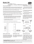
single wall tanks if dimension “B” (see illustration) is
between 3" and 6". If “B” dimension is 5"- 6", push
nipple down until the adaptor meets the collar.
However, the ullage will be affected by the length
of dimension “B”.
For “B” dimensions greater than 6", a different
2" diameter nipple length will need to be determined.
See illustration for determining dimension “C”.
Instructions for installations where the
4" long nipple is adequate, simply proceed
with the following steps:
1. Remove the special adapter from the inlet
of the nipple.
2. Remove the collar and nipple from the inlet
of the valve.
CAUTION! CARE MUST BE TAKEN TO PREVENT
DAMAGE TO THE FLOAT AND LINKAGE.
3. Apply a gasoline-resistant sealant to the outlet end
of the nipple and install it into the inlet of the valve.
4. Apply a gasoline-resistant sealant to the inlet end
of the nipple and thread the adapter in place.
5. Tighten the three (3) set screws in the collar.
6. Stand the valve upright, lift the float and release
it to make sure it works freely.
7. Apply a gasoline-resistant sealant to the threads of
the 4" fitting in the top of the tank. Slide the valve
assembly through the fitting.
8. Thread the collar onto the fitting. The valve is now
ready for operation.
Instructions for installations where a longer, 2"
diameter nipple (dimension “C”) must be used, i.e., a
nipple length greater than 4". See Illustration for
determining length of nipple.
If dimension “B” is greater than 6", proceed
with the following steps:
1. Determine dimension “C” (length of 2" diameter
nipple) by adding dimension “A” and “B” and
subtracting 8": A+B - 8"= C. Note: “A” dimension
must be a minimum of 7".
2. Cut and thread the new nipple which corresponds
to dimension “C”.
3. Remove adapter from the inlet of the existing
nipple and slide the collar off the nipple.
4. Remove the existing nipple from the valve.
5. Apply a gasoline-resistant sealant to one end of the
new nipple and thread it into the inlet of the valve.
6. Apply a liberal amount of grease to the o-ring in the
collar and slide the collar onto the nipple with the
4" threaded end toward the valve for a distance of
11⁄4". Tighten the 3 set screws.
7. Apply a gasoline-resistant sealant to the inlet end of
the nipple and thread the adapter in place.
8. Stand the assembly upright, lift the float and
release it to make sure it works freely.
9. Apply a gasoline-resistant sealant to the threads of
the 4" fitting in the top of the tank and slide the
valve assembly through the fitting.
10. Thread the collar onto the fitting. The valve is
now ready for operation.
Note: OPW recommends using a drop tube, such
as the OPW 61FT Series with all 61ƒSTOPs.
OPERATING PROCEDURES
CAUTION: READ THESE INSTRUCTIONS
CAREFULLY AND COMPLETELY BEFORE
OPERATING THIS DEVICE.
The 61ƒSTOP-1000 “The Stopper” is provided
a special adaptor which requires the appropriate
attachment for connection to achieve a tight fit.
CAUTION! OPERATIONS PROCEDURES CONTINUED
ON NEXT PAGE.
Pistola
equipada
con
acoplador
con bloqueo
de leva
OPW ofrece conector con bloqueo de
leva en nuestra pistola manual estándar
190, para ser usada con “The Stopper”.
Esta nueva conexión con bloqueo
de leva provee alto caudal confiable y
abastecimientos de gran volumen
sin derrames.
Otras características de la pistola
incluyen: cuerpo liviano de aluminio,
obturadores dobles para fácil apertura
contra la presión de entrada, enganche
para mantener abierta la pistola de
cuatro posiciones y área grande en la
palanca para mejor control.
PROCEDIMIENTOS PARA OPERACION
CUIDADO: LEA ESTAS INSTRUCCIONES POR COMPLETO
Y CON ATENCION ANTES DE OPERAR EL DISPOSITIVO.
El 61ƒStop-1000 “The Stopper” viene provista de una
adaptador especial que requiere ser instalado correctamente
para lograr un encaje apretado.
PROCEDIMIENTOS PARA ABASTECIMIENTO:
1. Asegúrese que la pistola esté provista del acoplador
correcto para lograr conexión adecuada.
2. Monte el acoplador al adaptador.
3. Active la bomba.
4. Abra la pistola despacio.
5. Monitoree el indicador de nivel de líquido durante
abastecimiento.
6. Observe la manguera ya que cualquier movimiento
rápido indica que ha ocurrido un cierre.
PROCEDIMIENTOS PARA DESCONEXION:
1. Después de ocurrir corte, cierre la pistola.
© Copyright 2000, OPW Fueling Components
2. Desactive la bomba en el vehículo de transporte.
3. Vuelva a abrir la pistola y espere aproximadamente dos
minutos. Esto permite que se reduzca la presión en la
manguera.
¡CUIDADO! SI SE TRATA DE DESCONECTAR EL
ACOPLADOR CUANDO HAY PRESION EN LA MANGUERA
SE DERRAMARA PRODUCTO.
4. Cierre la pistola y desacople la conexión despacio.
5. Remueva la pistola cuidadosamente y reemplace
la tapa.
OPW
®
FUELING COMPONENTS
A DOVER RESOURCES COMPANY
P.O. Box 405003 Cincinnati, Ohio 45240-5003
(513)870-3219 (800)422-2525 (Sólo órdenes)
(513)870-3100 (Otras Ilamadas)
Intn'l Ph: (513) 870-3315
Intn'l Fax: (513) 870-3157
Printed In USA
Nozzle
equipped
with
cam-lock
coupler
OPW offers a cam-lock connector for
our standard 190 manual nozzle, for use
with “The Stopper”.
This new cam-lock connection provides
for reliable, high flow and mess-free bulk
fuel deliveries.
Additional nozzle features include:
Lightweight aluminum body, dual poppets
for easy opening against inlet pressure,
four position hold-open latch and large
lever area for maximum grip.
FILLING PROCEDURES:
1. Make sure the nozzle is equipped with the appropriate coupler to achieve an adequate connection.
2. Attach the coupler to the adaptor.
3. Turn on the pump.
4. Slowly open the nozzle.
5. Monitor the liquid level gauge during fill.
6. Watch for any quick movement of the hose
which indicates that shut-off has occurred.
CAUTION! ATTEMPTING TO DISCONNECT THE
COUPLER WITH PRESSURE IN THE HOSE WILL
RESULT IN THE RELEASE OF PRODUCT.
4. Close the nozzle and slowly uncouple the
connection.
5. Remove the nozzle carefully and replace the cap.
DISCONNECTION PROCEDURES:
1. After shut-off has occurred, close the nozzle.
2. Turn off the pump at the transport vehicle.
3. Re-open the nozzle and wait approximately
2 minutes. This allows the pressure in the hose
to be reduced.
© Copyright 2000, OPW Fueling Components
Printed In USA
OPW
®
INSTRUCCIONES
PARA
INSTALACION
H-12676-M
OPW 61ƒSTOP-1000 & -100M “THE STOPPER”
La 61ƒSTOP-1000 es una válvula de prevención de sobrellenado para ser usada con tanques exteriores de almacenamiento (AST) donde el producto es bombeado del vehículo de transporte directamente al AST. Ha sido diseñada para
cerrar el flujo de producto cuando el líquido en el tanque
llega a un nivel predeterminado.
ADVERTENCIA: La 61ƒSTOP HA SIDO DISEÑADA
PARA APLICACIONES DE LLENADO HERMETICO Y
DEBE SER USADA CON LAS CONEXIONES APROPIADAS.
SI NO SE CONECTA DEBIDAMENTE LA MANGUERA DE
DESCARGA O SI NO SE DESCONECTA DEBIDAMENTE
UNA LINEA LLENA DE LIQUIDO, SE PUEDE OCASIONAR
UN DERRAME EXTREMADAMENTE PELIGROSO, RESULTANDO EN SERIAS LESIONES PERSONALES Y DAÑOS
MATERIALES, FUEGO, EXPLOSION O CONTAMINACION
DEL SUELO Y EL AGUA.
INSTALACION
La 61ƒSTOP-1000 ha sido empaquetada con un niple de
tubería de 2” de diámetro por 4” de largo, enroscado sin
apretar en la entrada de la válvula. Por encima del niple de
4”, se ha ensamblado sin apretar un collar para conectar la
unidad al tubo de entrada de 4” del tanque. Un adaptador
especial con barra cruzada ha sido enroscado sin apretar en
el extremo de entrada del niple. Este niple puede ser usado
en tanques de pared simple si la dimensión “B” (vea ilustración) es entre 3” y 6”. Si la dimensión “B” es de 5” a 6”,
empuje el niple hacia abajo hasta que el adaptador se
encuentre con el collar. Sin embargo, la merma se verá afectada por el largo de la dimensión “B”.
Para dimensiones “B” mayores de 6”, se necesita
determinar un largo diferente para el niple de 2”. Vea
la ilustración para determinar la dimensión “C”.
Instrucciones para instalaciones en las que el
niple de 4” de largo es adecuado. Proceda con los
pasos siguientes:
1. Remueva el adaptador especial de la entrada
del niple.
2. Remueva el collar y el niple de la entrada
de la válvula.
¡CUIDADO! SE DEBE TENER MUCHO CUIDADO PARA NO
DAÑAR EL FLOTADOR Y LAS UNIONES.
3. Aplique un sellador resistente a la gasolina al
extremo de salida del niple e instálelo en la entrada
de la válvula.
4. Aplique un sellador resistente a la gasolina al extremo
de entrada del niple y enrosque el adaptador.
5. Apriete los tres (3) tornillos en el collar.
6. Posicione la válvula hacia arriba, levante el flotador y
déjelo ir para asegurarse que está trabajando correctamente.
7. Aplique un sellador resistente a la gasolina a los
enrosques de la pieza de unión encima del tanque.
Deslice la válvula a través de la pieza de unión.
8. Enrosque el collar a la pieza de unión. La válvula está
pronta para operación.
Instrucciones para instalaciones en las que se debe usar
un niple de 2” de diámetro más largo (dimensión “C”),
por ejemplo, un niple de más de 4” de largo. Vea la ilustración para determinar el largo del niple.
Si la dimensión “B” es mayor de 6”, proceda
con los pasos siguientes:
1. Determine la dimensión “C” (el largo del niple de
2” de diámetro) sumando la dimensión “A” y “B” y
restando 8”. A+B - 8”=C. Note que la dimensión
“A” debe ser por lo mínimo 7”.
2. Corte y enrosque el nuevo niple que corresponde
a la dimensión “C”.
3. Remueva el adaptador de la entrada del niple
existente y deslice el collar fuera del niple.
4. Remueva el niple existente de la válvula.
5. Aplique un sellador resistente a la gasolina al un
extremo del nuevo niple e enrósquelo en la entrada
de la válvula.
6. Aplique una gran cantidad de grasa al anillo O en el
collar y deslice el collar en el niple con el extremo
enroscado de 4” hacia la válvula a una distancia de
1-1/4”. Apriete los 3 tornillos.
7. Aplique un sellador resistente a la gasolina al extremo
de entrada del niple y enrosque el adaptador en
su lugar.
8. Posicione la válvula hacia arriba, levante el flotador
y déjelo ir para asegurarse que está trabajando
correctamente.
9. Aplique un sellador resistente a la gasolina a los
enrosques de la pieza de unión encima del tanque.
Deslice la válvula a través de la pieza de unión.
10. Enrosque el collar a la pieza de unión. La válvula está
pronta para operación.
Nota: OPW recomienda utilizar un tubo de
ilenado como el de la Serie OPW 61FT
en todos los 61ƒSTOPS
¡CUIDADO! VEA LAS INSTRUCCIONES DE OPERACION.