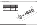
1
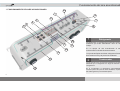
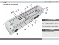
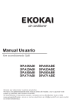
Aire acondicionado
Rodoviario - Urbano
Manual del Proprietario
Certificado de Garantía
CC 305
CC 335
CC 355
Air Conditioner
Road bus - City bus
Owner’s Manual
Warranty Certofocate
Para obtener el mejor rendimiento del aire acondicionado recomendamos
leer atentamente este manual antes de iniciar la operacion.
Tenga este manual en el vehículo para consultas.
To get the best performance out of the air conditioner, we suggest you
carefully this manual before starting the operatin.
Keep this manual handy in the vehicle for consultations.
1° edición/edition: Febrero/February - 2011
Código/Ref. number: 036-00198-000
Terminos de garantía
TERMINOS DE GARANTÍA SPHEROS
LA SPHEROS CLIMATIZAÇÃO DO BRASIL S/A garantiza sus productos por
el período de un año de acordo con los terminos relacionados a seguir:
1 - La garantia tendrá validade por el plazo arriba especificado, empezando a
partir de la fecha de instalación del equipo, que consta en el cetificado de
garantía, mismo que la propiedad del producto canbie de dueño.
2 - Si el equipo es instalado por un tercero la Spheros garantiza solamente el
producto y no la instalacíon.
3 - Durante el período estipulado, la garantia cubre totalmente la mano de
obra y piezas para reparos de defectos debidamente constatados como
siendo de: fabricación del equipo; falla prematura de material y defectos de
componentes utilizados en la fabricación del mismo.
4 - Solamente un técnico de la red de servicio autorizado Spheros está
habilitado a reparar defectos cubiertos por la garantia.
5 - La aprobación de la garantía está acondicionada al analice técnica del
defecto presentado en el componente y las condiciones operacionales a que
el equipo fue sometido.
6 - Ninguna reivindicación será acepta si el vehículo continua siendo usado
después de constatado el defecto, mismo que haya falta de piezas, atraso en
el transporte o cualquier otro incidente.
7 - La garantía de componentes utilizados en montaje de equipos Spheros
que poseen red propia de assistencia técnica será obtenidca junto a sua red
mediante la presentación del cetrificado de garantía Spheros. Como ejemplo
el caso del alternador, que debe ser encaminado para la rede Boch.
8 - LA GARANTÍA PERDERÁ SU VALIDAD:
a)Si la instalación o utilización del producto estuviera en desacuerdo con las
recomendaciones técnicas de la Spheros.
b)Si el producto sufrir cualquier daño provocado por accidente, agente de la
naturaleza, malos tratos , o aún alteraciones y reparos realizados por
personas no autorizadas.
c)Si el certicifado de garantía o el número de serie estuvira adulterado,
rasurado o damnificado.
d)Si defectos y desempeño insatisfactorios sean provocados por la
utilización de piezas no originales y en desacuerdo con las especificaciones
técnicas de la Spheros.
9 - LA GARANTÍA NO CUBRE:
a)Translado del producto para reparos. Si el consumidor desea ser atendido
en sus instalaciones, quedará a criterio del Servicio Autorizado la cobanza o
cortesía de la tasa de visita.
b)La assistencia al consumidor, gratuita o remunerada, en ciudades que no
posseen Servicio Autorizado. Así los costos con traslados son de total
responsabilidad del propietario.
c)Falta de mantenimiento preventivo, conforme descrito en este manul, en el
ítem mantenimiento preventivo.
d)Piezas que sufrieron desgaste considerados naturales. Son considerados
componentes de desgastes naturales: rodamientos, correas, filtro en
general, aceites lubrificante, relees y fusibles.
e)Pérdida o lucros cersantes ocasionados por la parada del vehículo devido
al mal funcionamiento del equipo de aire acondicionado
10 - LA GARANTÍA SOLAMENTE SERÁ VALIDADA MEDIANTE LA
PRESENTACIÓN DEL CERTIFICADO DE GARANTÍA ORIGINAL.
Warranty terms
SPHEROS WARRANT TERMS
SPHEROS CLIMATIZAÇÃO DO BRASIL S/A warrants its products for one
year in accordance with the terms listed below:
1 - The warranty will be valid for the period above specified, counting from the
date when the equipament is installed in keeping with the warrant certificate ,
even after the property there of has ben transfered.
2 - Should the equipamente be installed by a third part , Spheros warrant only
the product and not its istalations.
3 - During the stipulated period, the warranty completely covers the
workmanship and spare parts used to repair defects duly identified as being:
premature failure of material and componentes defects used on its
manufacture.
4 - Only a techinician from the Spheros authorized network of services is
qualified to repair the defects coverd under the warranty.
5 - The warranty approval is subject to the techinical analysis of the defects
shown in the components and operational conditions to which the equipment
has been subjected.
6 - No claims will be accepted if the vehicle is still in use after the defect is
found, even if there is lack of pieces, delay in transportation or any other such
incident.
7 - The warranty of the componentes used in the assembly of Spheros’
equipmente, which have their own technical assistence network, will be
obtained from their own network, by presenting the Spheros warranty
certificate. Taking for exemple the alternator case, it sohould be forwarded to
the Bosch network.
8 - THE WARRANT LOSES ITS VALIDITY
a) If the installation or use of the product is not in accordance with the Spheros
technical recommendations.
b) If the product suffers any damage caused by accident, nature agents,
misuse, or even alterations and repairs performed by unauthorized
personnel.
c) If the warranty certificate and/or the serial number of the product are
adulterated, overwritten or damaged.
d) If defects or unsatisfactory performance are caused by the use of nonoriginal spare parts and in disagreement with the technical sapefications from
Spheros.
9 - THE WARRANTY DOES NOT COVER:
a) Displacement of the bus for repairing of the equipmet. In case the customer
requests to be attended in the same place where products is operating, the
collection or not of the visitation charge will be the criterion of the authorized
service provider.
b) The attending to the consumer, free or paid, in cities that do not have
authorized services providers. So the expenses with displacement are the
sole responsibility of the owner.
c) Lack of proper preventive maintenance, as described in the preventive
maintenance item in this manual.
d) Parts that wear out naturally: bearings, belts, filters in general, lubricanting
oil, relays an fuses.
e) Losses or losses of profits coused by the grounding of the vehicle due to the
equipmente not funcitioning.
10 - THE WARRANTY WILL ONLY BE VALID BY PRESENTING THE
ORIGINAL WARRANTY CERTIFICATE.
Introducciones/Introduction
INTRODUCCIONES
INTRODUCTION
La Spheros desarolla sus productos preocupada en ofrecer a los
pasajeros un ambiente confortable, buscando siempre las mejores
condiciones de climatización.
Spheros develops its products with a view to offering passengers a
comfortable environment, always seeking for the best condition of
weathrization
Los equipos posseen design que proporciona una perfecta integracíon
con el vehículo y que facilita la operación y el mantenimiento. Con un
diseño optimizado, assegura la capacidad de resfriamiento con bajo
nivel de ruido.
The equipmentes boasts a disign that provides seamless integration
with the vehicle, facilitating its operation and maintenence. With
optimized design, high-cooling capacity and low noise assured.
Este manual foi desarollado con la finalidad de presentar aspectos
importantes del funcionamiento, operacíon y mantenimiento, para que
se obtenga el mejor desempeño del equipo de aire acondicionado.
Para asegurar que el equipo tenga un larga vida útil y libre de problemas
es imprescindible que las instrucciones de operación y mantenimiento
descritas en este manual sean seguidas y ejecutadas periódicamente.
Los controles instalados por Spheros y utilizados por el condutor están
debidamente ilustrados y explicados en este manual. Es importante que
el conductor lea atentamente las instrucciones del equipo antes de
iniciar la operación del equipo de aire aconcicionado.
La Spheros mantiene una red de servicio autorizado com herramientas,
aparatos y un equipo de personas entrenadas para ejecutar cualqier tipo
de manutención dentro de los padrones de calidad.
Agradecemos la preferência por los productos Spheros. En caso de
dudas entre en contacto con la red de servicio autorizado Spheros más
próximo o cominíquese con el departamento de asistencia técnica en la
fabrica.
This manual was developed for the purose to presenting some
important aspects of function, operation and maintenece, so as to get
optimum performance out of the air conditioning equipment.
To ensure that the equeipament has a long, useful and trouble free life, it
is essential that the operations and maintenance instructions discribd in
this manual are followed and performed regularlly.
The controls installed by Spheros, which ar used by the driver, are duly
illustrated and explained in this manual. It’s important read the manual
before starting to operate the air conditoning equipment.
Spheros maintains a network of authorized services providers with
tools, equipments and a team of professionals trained to perform any
type of maintenance within the quality standard.
Thank you for choosing Spheros products. For questions please
contact the nearest Spheros authorized services provider or contact the
tecnical assistance departament.
Índice/Index
1 FUNCIONAMIENTO DEL AIRE ACONDICIONADO................................................... 5
1.2 OPERACIÓN DEL CONTROLADOR .................................................... 7
1.2.1 ACCIONAMENTO DEL CONTROLADOR.......................................... 8
1.2.2 LECTURA DE LA TEMPERATURA.................................................... 8
1.2.3 PROGRAMANDO EL SET-POINT...................................................... 8
1.2.4 MODO AUTOMÁTICO........................................................................ 8
1.2.5 MODO VENTILACIÓN........................................................................ 8
1.2.6 MODO REFRIGERACIÓN.................................................................. 9
1.2.7 MODO CALENTAMIENTO.................................................................. 9
1.2.8 CALENTAMIENTO POR CONVECTORES........................................ 9
1.2.9 RENOVACIÓN DEL AIRE................................................................... 9
1.2.10 TEMPERATURA INTERNA E EXTERNA......................................... 9
1.2.11 FALLAS............................................................................................. 9
1.2.11.1 ALARMA DE FALLAS CONTROLADOR GL-W163..... 10
1.2.11.2 ALARMA DE FALLAS CONTROLADOR GL-W210..... 10
2 DESCRIPCIÓN DEL EQUIPO..................................................................................... 11
2.1 ESPECIFICACIONES TÉCNICAS......................................................... 11
2.2 COMPONENTES DEL EQUIPO............................................................ 12
2.3 COMPONENTES DEL COMPRESOR................................................. 13
2.4 COMPONENTES DE LA EMBRAGUE ELECTROMAGNÉTICA........... 14
3 MANUTENCIÓN PREVENTIVA.................................................................................. 15
3.1 ALERTAS DE SEGURIDAD................................................................... 15
3.2 GAS REFRIGERANTE R 134a.............................................................. 16
3.3 ACEITE.................................................................................................. 16
3.4 FILTRO DESHIDRATADOR................................................................... 16
3.5 SELLO DE VEDACIÓN DEL COMPRESOR......................................... 16
3.6 EMBRAGUE ELECTROMAGNÉTICA................................................... 16
3.7 DUCTOS................................................................................................ 16
3.8 NO COMPRE PIEZAS REMANUFACTURADAS.................................. 16
3.9 TABLA DE MANUTENCIÓN PREVENTIVA........................................... 17
3.10 IDENTIFICACIÓN DEL EQUIPO......................................................... 18
4 SISTEMA ELÉCTRICO............................................................................................... 33
4.1 LEYENDAS ELÉCTRICAS.................................................................... 33
4.2 CONECCIÓN DEL CONTROLADOR ................................................... 34
4.3 PLACA COMANDO ELÉCTRICO GL-T046........................................... 35
4.4 ESQUEMA ELÉCTRICO GL-T-046 COM CONTROLADOR GL-W161. 36
4.5 PLACA COMANDO ELÉCTRICO GL-T047........................................... 37
4.6 ESQUEMA ELÉCTRICO GL-T047 COM CONTROLADOR GL-W163.. 38
4.7 ESQUEMA ELÉCTRICO GL-T047 COM CONTROLADOR GL-W210.. 39
1 OPERATION THE AIR CONDITIONER....................................................................
1.2 CONTROLLER....................................................................................
1.2.1 SETTING THE CONTROLLER.........................................................
1.2.2 READING THE TEMPERATURE.....................................................
1.2.3 PROGRAMMING THE SET-POINT..................................................
1.2.4 AUTOMATIC MODE ........................................................................
1.2.5 VENTILATION MODE ......................................................................
1.2.6 COOLING MODE.............................................................................
1.2.7 ROOF HEATING MODE ..................................................................
1.2.8 HEATING BY CONVYORS...............................................................
1.2.9 AIR REFRESHMENT........................................................................
1.2.10 iNTERNAL AND EXTERNAL TEMPERATURE .............................
1.2.11 FAILURES.......................................................................................
1.2.11.1 CONTROLLER GL-W163 ALARM FAILURES .........
1.2.11.2 CONTROLLER GL-W210 ALARM FAILURES .........
2 EQUIPMENT DESCRIPTION...................................................................................
2.1 TECHNICAL DATA SHEET .................................................................
2.2 EQUIPMENT COMPONENTS.............................................................
2.3 COMPRESSOR COMPONENTS........................................................
2.4 MAGNETIC CLUTCH COMPONENTS...............................................
3 PREVENTIVE MAINTENANCE................................................................................
3.1 SECURYTY WARNINGS.....................................................................
3.2 REFRIGERANT GAS R134a...............................................................
3.3 OIL ......................................................................................................
3.4 DRIER FILTER.....................................................................................
3.5 COMPRESSOR SEAL SEALING........................................................
3.6 CLUTCH..............................................................................................
3.7 AIR DUCTS..........................................................................................
3.8 SAY NO TO REMANUFACTURED PARTS.........................................
3.9 FREQUENCY SCHEDULE FOR PREVENTIVE MAINTENANCE......
3.10 EQUIPMENT IDENTIFICATION........................................................
4 ELETRICAL SYSTEM...............................................................................................
4.1 ELETRICAL LEGENDS ......................................................................
4.2 CONTROLLER CONECTIONS...........................................................
4.3 RELAY PLATE GL-T046......................................................................
4.4 ELETRICAL SHEME GL-T-046 WITH CONTROLLER GL-W161.......
4.5 RELAY PLATE GL-T047.....................................................................
4.6 ELETRICAL SHEME GL-T047 WITH CONTROLLER GL-W163........
4.7 ELETRICAL SHEME GL-T047 WITH CONTROLLER GL-W210........
19
21
22
22
22
22
22
23
23
23
23
23
24
24
24
25
25
26
27
28
29
29
30
30
30
30
30
30
30
31
32
33
33
34
35
36
37
38
39
Funcionamento del aire acondicionado
1 FUNCIONAMIENTO DEL AIRE ACONDICIONADO
16
1
2
3
4
5
13
15
7
6
14
11
12
8
17
9
1
Refrigerante
Generalmente, un refrigerante es caulquier cuerpo o
sustancia que actua absorbiendo calor de otro
cuerpo.
En un equipo de aire acondicinado el esta
enclausurado confinado dentro del sistema
Los productos Spheros utilizam refrigerante R134a,
de acuerdo con la ley de proteccíon ambiental.
2
Condensador
La principal funcción es propiciar la disipación del calor
absorbido por el refrigerante a lo largo del sistema de
refregeración.
10
5
En el condensador el refrigerante supercalentado,
mientras perde calor para el medio ambiente, el passa
del estado gaseoso para el estado liquido.
Funcionamento
condicionado
Funcionamiento do
delaraire
acondicionado
3
Filtro deshidratador
Su objetivo es retener las impurezas y/o humedad
que puedan haber en el sistema para evitar que
lleguen en la valvula e expancíón.
4
Válvula termostática de expanción
La válvula de expancíon restringe la entra de
refrigerante que viene del condensador en alta
presión y su funccion es regular el flujo de
refrigerante que passa en el evaporador buscando
mantener estable la presión y la temperatura en la
salida de la serpentina.
5
Evaporador
Es en el evaporador que el refrigerante, ahora en
baja presión, pasa del estado líoquido para el
gaseoso, absorbiendo en este proceso el calor del
ambiente interno del bus.
6
Compresor
Cuando está en funcionamento, el compresor
succiona el refrigerante del evaporador en el estado
gaseoso y en baja presión, lo comprime
aumentando la presión y la temperatura y lo
descarga para el condensador.
7
Accionamento del compresor
El compressor es tracuinado por el motor del
vehiculo a través de un sistema de correas y
accionado por un embrague eletromagnético
cuando el aire acondicionado está funcionado en el
‘modo refrigeración’.
8
Ventilador del condensador
Los ventiladores del condensador, asi como el
compressor , son activados cuando el aire
acondicionado funciona en el ‘modo refrigeracíon’
9
Ventilador del evaporador
Los ventiladores del evaporador son activados en
los modos ventilacíon o refrigeración y puede operar
en dos velocidades.
El controle de velocidade puede ser automático o
manual.
10
Controlador
Instalado en el tablero de instrumentos, permite al
conductor programar la temperatura del set-point y
visualizar el valor de la temperatura interna del
vehículo, ofrecendo el control total del clima interno
del bus.
13
Presostatos
Los presostatos son dispositivos eléctricos que
monitorizan las presiones de operacíon del equipo
del aire acondicionado.
Siempre que occurrir una alteración en las presiones
normales de operación, para previnir daños, el
compresor es apagado inmediatamente.
Obs.: Las pressiones son monitorizadas
continuamente incluso cuando el aire
acondicionado este apagado.
14
Renovación del aire
Permite la entrada de aire exteno con la finalidad de
retirar los olores y impurezas no deseadas en el
interior del vehículo
15
Filtro del aire
Set-point: es el valor de la temperatura deseada en
el interior del vehiculo, ajustada por el operador)
El filtro del retorno de aire retiene las impurezas
suspendidas en el aire evitando la accumulación
de residuos en los serpentins del evaporador.
11
16
Sensor de temperatura
La temperatura interna es detectado por el sensor
de temperatura ubicado en el retorno de aire.
12
Placa de reles
La placa de reles recibe los comandos del
controlador y activa los ventiladores del
condensador, evaporador y el compresor de
acuerdo con el modo de operación seleccionado.
Circulación del aire
El aire, despues de canbiar calor en el evaporador
es distribuido e el interior de bus por ductos.
17
Desague
Sirven para conduzir la umedad condensada en los
serpentins del evaporador acumulada en la bandeja
de condensación hacia fuera del vehiculo
6
Funcionamento del aire acondicionado
1.2 OPERACIÓN DEL CONTROLADOR
CONTROLADOR GL-W210
CONTROLADOR GL-W163
8
1
9 10 11
2
3
8
13
1
7
2
6
4
5
6
4
1 - Display numérico
8 - Indicativo "modo refrigeración/calentamiento’’
2 - Tecla control refrigeración/calentamimento automático (AUTO)
9 - Indicativo "modo automático’’
3 - Tecla control de ventilación (VENT.)
10- Indicativo "modo ventilación velocidad baja’’
4 - Tecla control de renovación del aire (RENOV.)
11- Indicativo "modo ventilación velocidad alta"
5 - Tecla (AUMENTA)
12- Indicativo "modo renovación del aire’’
6 - Tecla (DISMINUYE)
13- Indicativo "verificación de temperaturas interna/externa"
7 - Tecla verificación de temperatura interna/externa (TEMP.)
7
3
12
12
5
9 10 11
Funcionamiento del aire acondicionado
1.2.1 ACCIONAMIENTO DEL CONTROLADOR
1.2.4 MODO AUTMÁTICO
El controlador se prenderá cuando es accionada la llave de ignición del bus.
1- Para seleccionar el "modo automático" presione la tecla (AUTO ).
El display, primeramente mostrará la versión del software del controlador,
después mostrará la temperatura interna del vehículo.
En el "modo automático" el controlador hará el control automatico de las
funcciones disponibles (refrigeración o calentamiento), buscando la mejor
condición de climatización en función de la temperatura del set-poit
Antes de poner el motor en marcha el motor, el display mostrará la falla
minitoreo del alternador. (ver item 1.2.11)
1.2.2 LECTURA DE LA TEMPERATURA
2 - Para desactivar el ‘modo automático’, presione nuevamente la tecla
(AUTO).
El controlador monitorea sensores de temperatura distribuidos en el vehículo
conforme se describe abajo:
a) sensor de temperatura interna:
Ubicado en el retorno de aire a condicionado.
b) sensor de temperatura externa*:
Ubicado en el exterior del equipo de aire acondicionado.
c) sensor de temperatura de los dutos*:
Ubicado en los ductos de aire.
*Solamente en equipos que posseen calentamiento.
1.2.5 MODO VENTILACIÓN
El ‘modo ventilación’ proporciona dos velocidades de operación:
1 - Con el ‘modo automático’ desactivado pressione la tecla (VENT) y el
‘modo ventilación’ entrará en operación a velocidad baja. Para informar este
modo el indicativo (10) quedará encendido.
1.2.3 PROGRAMANDO EL SET-POINT
2 - Para seleccionar la velocidad alta, presione nuevamente la tecla (VENT).
El indicativo (11) encenderá para informar esta funcción.
1 - Para ajustar la temperatura del set-point pressione una de las teclas
(AUMENTA) o (DISMINUYE). La temperatura del set-point aparecerá
parpadeando en el display.
3 - Para desactivar el ‘modo ventilación’ pressione una vez más la tecla
(VENT).
2 - Para programarlo basta presionar la tecla (AUMENTA) para aumentar la
temperatura o la tecla (DISMINUYE) para disminuir la temperatura, hasta
encontrar la temperatura deseada.
Con el ‘ modo automático’ activado la ventilación es normalmente automático
y será informada por el indicativo (9) encendido. Aunque, la velocidad puede
ser alterada manualmente, siguiendo los mismos pasos informados
anteriormente.
3 - Después de la temperatura deseada definida, el display continuará
parpadeando por 5 segundos. Cuando parar, el display mostrará la
temperatura interna del vehículo y la temperatura del set-point estará
reprogramada.
4 - Para volver al control automático, presione la tecla (VENT) hasta que el
indicativo (9) encienda, informando que la ventilación está en modo
automático.
8
Funcionamiento del aire acondicionado
1.2.6 MODO REFRIGERACIÓN
1.2.9 RENOVACIÓN DEL AIRE
Después de seleccionar el ‘modo automático’ conforme item 1.2.4, si la
temperatura intena del vehículo estuviera arriba de set-point el equipo
pasará a trabajar en el ‘modo refrigeración’.
1 - Con el aire acondicionado operando en ‘modo automático’ la renovación
funcionará de acuerdo a la temperatura del set-point buscando la mejor
condición de comodidad para los pasajeros.
Siempre que el sistema inicie en el ‘modo refrigeración’ los ventiladores del
evaporador empezarán en el modo automático. Pero, la velocidad puede ser
alterada manualmente (ver item 1.2.5)
Isso este igual para los dos modos: refrigeración y calentamiento.
Obs.: El accionamiento de los ventiladores del evaporador en el modo
automático es hecho de acuerdo con la programación del set-point.
2 - Durante la refrigeración o calentamiento, la renovación del aire podra se
accionada manualmente presionando la tecla (RENOV). La renovación
permanecerá abierta durante 10 segundos. Después de cumplido el tiempo,
la renovación cerrará y volverá al ciclo automático.
1.2.7
MODO CALENTAMIENTO
1 - Después de seleccionar el ‘ modo automático, conforme item 1.2.4, si la
temperatura interna del vehículo estuviera abajo de la temperatura de setpoint el equipo pasará a operar en el ‘modo calentamiento’.
Obs.: La ventilación en este modo funcionará apenas a baja.
1.2.8 CALENTAMIENTO POR CONVECTORES*
El ‘modo calentamiento por convectores’ es accionado de la misma forma
que en el ‘modo calentamiento’.
a) El indicativo (13) encendido informará cuando la renovación del aire
estuviera abierta.
Obs.: En caso de que la renovación del aire estuviera abierta, cuando el
‘modo refrigeración’ entre en operación la misma será automaticamente
cerrada.
1.2.10 TEMPERATURA INTERNA E EXTERNA
El display normalmente muestra la temperatura interna del vehículo.
1 - para verificar la temperatura externa presione la tecla (TEMP). El display
mostrará la temperatura externa por 5 segundos. Mientras la temperatura
externa aparece en el display el indicativo (13) quedará encendido.
Después de 5 segundos el display volverá a mostrar la temperatura intena y
el indicativo (13) se apagará.
Se la tecla (TEMP) fuera presionada antes del tiempo predefinido de 5
segundos, el display mostrará la temperatura interna nuevamente.
*Convectores – serpentinas de calentamiento instaladas por la montadora.
Normalmente están ubicados en las laterales internas de ómnibus por debajo
de los asientos.
9
Funcionamiento del aire acondicionado
1.2.11.2 ALARMA DE FALLAS CONTROLADOR GL-W210
1.2.11 FALLAS
Cuando ocurriera alguna falla en el sistema del aire acondicionado, el display
mostrará una alarma conforme tabla abajo.
Importante:
Al identificar cualquier falla en el sistema del aire
acondicionado, el vehículo deberá ser llevado a un puesto de servicio
autorizado Spheros.
1.2.11.1 ALARMA DE FALLAS DEL CONTROLADOR GL-W163
FALHA
DESCRIPCIÓN
Falla del alternador
Falla del sensor del retorno del aire
Falla del sensor del ducto
Falla del sensor externo
FALLA
DESCRIPCIÓN
Falla de presostato
Sensor de temperatura abierto
Sensor de temperatura en corto
Falla del alternador
Falla de presostatos
Falla de comunicación
Falla de conección de la válvula
1 - Este controlador posee un parámetro para monitoreo del alternador. En caso de
falla en el alternador el display mostrará la alarma (AI), pero las salidas continuarán
energizadas.
2 - En caso de falla del sensor del retorno del aire, el display mostrará (FI).
1 - Si ocurriera alguna falla de presostato, el display mostratá la alarma (HA) y el
sistema apagará el compresor. Después de corregida la falla, el sistema aguardará 3
minutos para accionar nuevamente el compresor.
2 - Como el sistema opera en función de la temperatura interna, el controlador posee
dos códigos de falla para monitorear el sensor de temperatura:
a) Si el sensor de temperatura estuviera abierto el display mostrará (OP).
b) Si el sensor de temperatura estuviera en corto circuito el display mostrará (SC)
3 - Este controlador posee un parámetro para monitorear el alternador. Caso el
alternador no estuviera cargando el, display mostrará el código (AL).
3 - En caso de falla del sensor del ducto, el display mostrará (F3).
4 - En caso de falla del sensor externo, el display mostrará (F5).
5 - Si ocurriera falla de presión, el display mostrará la alarma (FP) y el sistema
apagará el compresor. El sistema aguardará 3 minutos para accionar nuevamente el
compresor después de corregida la falla.
6 - En caso de falla de comunicación el display mostrará (FC) y funcionará solamente
en modo refrigeración.
7 - En caso de falla eléctrica en la válvula de calefaccíon el display mostrará (EI).
10
Descripción del equipo
2 DESCRIPCIÓN DEL EQUIPO
2.1 ESPECIFICACIONES TÉCNICAS
AIRE ACONDITIONADO
Modelo
Capacidad de refrigeración
GAS REFRIGERANTE
Tipo
Cantidad
CC 305
108.000 BTU/h
CC 335
120.000 BTU/h
CC 355
136.500 BTU/hR
R 134a
6 kg*
R 134a
6 kg*
134a
7 kg*
EVAPORADOR
Modelo de ventiladores
Cantidad de ventiladores
Volumen de aire
Corriente nominal
centrífugo
4
4200 m3/h
46 A
centrífugo
6
6300 m3/h
69 A
centrífugo
6
6300 m3/h
69 A
CONDENSADOR
Modelo de ventiladores
Cantidad de ventiladores
Volumen de aire
Corriente nominal
axial
3
6800 m3/h
27 A
axial
3
6800 m3/h
27 A
axial
4
9120 m3/h
36 A
COMPRESOR
Modelo (Tipo alternativo)
Deslocacíon
Max. revolución por minuto
Aceite lubricante
Cantidad de aceite
Bitzer 4TFCY
470 cm3
3500 RPM
027-00002-000
2500 ml
Bitzer 4PFCY
558 cm3
3500 RPM
027-00002-000
2500 ml
Bitzer 4NFCY
647 cm3
3500 RPM
027-00002-000
2500 ml
electromagnética
24 v
electromagnética
24 v
electromagnética
24 v
EMBRAGUE
Tipo
Voltaje
* La cantidad de gas refrigerante está sujeta a alteraciones de acuerdo a la aplicación e instalación.
11
Descripción del equipo
2.2 COMPONENTES
DEL EQUIPO
3.2.1 Componentes
do Equipamento
1
2
7
10
8
3
11
4
9
5
CC 305
6
CC 335
CC 355
ITEM
DESCRIPTIÓN
CÓDIGO
1
Ventilador condensador 12” 24v
021-00015-000
021-00015-000
021-00015-000
2
Serpentín condensador
006-00157-000
006-00157-000
006-00142-000
3
Filtro deshidratador
012-00086-000
012-00086-000
012-00086-000
4
Válvula de servicio
012-00082-000
012-00082-000
012-00082-000
5
Tanque recibidor
038-00020-002
038-00020-002
038-00020-002
6
Ventilador evaporador 24V
021-00014-000
021-00014-000
021-00014-000
7
Válvula expanción
012-00081-000
012-00081-000
012-00081-000
8
Serpentín evaporador izquierdo
006-00138-000
006-00138-000
006-00134-000
9
Serpentín evaporador derecho
006-00139-000
006-00139-000
006-00135-000
10
Placa de relees
007-00017-000
007-00017-000
007-00017-000
11
Sensor de Temperatura
007-00042-000
007-00042-000
007-00042-000
12
Descripción del equipo
2.3 COMPONENTES DEL COMPRESOR
4TFCY
ITEM
11
17
19
20
14
13
1
12
9
16
L
R
10
15
7
8
18
4
2
6
3
13
5
DESCRIPCIÓN
4PFCY
4NFCY
CÓDIGO
CTD.
1
Bloco
014-00069-000
014-00069-000
014-00069-000
1
2
Cigueñal
014-00018-000
014-00018-000
014-00018-000
1
3
Balance delantero
014-00070-001
014-00071-000
014-00071-000
1
4
Balance trasero
014-00071-001
014-00070-000
014-00070-000
1
5
Kit guarnición
014-00054-001
014-00054-001
014-00054-002
1
6
Carter
014-00072-000
014-00072-000
014-00072-000
1
7
Filtro del aceite
014-00015-000
014-00015-000
014-00015-000
1
8
Conjunto pistón/biela
014-00052-000
014-00052-000
014-00053-000
4
9
Camisa pistón izquierdo
014-00073-003
014-00073-001
014-00073-002
2
10
Camisa pistón derecho
014-00074-003
014-00074-001
014-00074-002
2
11
Válvulas de servicio
014-00075-001
014-00075-001
014-00075-001
1
12
Conjunto placa de válvula
014-00168-000
014-00050-000
014-00051-000
2
13
Bomba del aceite
014-00076-000
014-00076-000
014-00076-000
1
14
Tapa trasera
014-00079-000
014-00077-000
014-00077-000
1
15
Tapa delantera
014-00077-000
014-00079-000
014-00079-000
1
16
Rodamiento
014-00078-000
014-00078-000
014-00078-000
1
17
Cabeza
014-00080-000
014-00080-000
014-00080-000
2
18
Sello mecânico
014-00013-000
014-00013-000
014-00013-000
1
19
Válvula de Alívio
014-00116-000
014-00116-000
014-00116-000
1
20
Mufla de descarga
014-00175-000
014-00175-000
014-00175-000
1
Descripción del equipo
2.4 COMPONENTES DA EMBREAGEM ELETROMAGNÉTICA
ITEM
DESCRICÍON
CÓDIGO
CTD.
1
Conjunto embreague
041-00226-000
1
2
Polea 2A/2B
014-00097-000
1
3
Kit embreague
029-00073-000
1
4
Magneto
029-00052-000
1
5
Rodamiento
029-00008-000
1
6
Tornillo
017-00104-000
1
200mm
4
5
2
3
6
1
14
Manutención Preventiva
3 MANUTENCIÓN PREVENTIVA
Para garantizar el perfecto funccionamiento del aire acondicionado es
necesario la realización de algunos precedimientos de manutención preventiva.
Esto evitará la perdida de capacidad; aumetará la vida útil de los componentes
del equipo y disminuirá los gastos con paradas innecessarias del vehículo.
3.1 ALERTA DE SEGURIDAD
1) Protección personal
El sistema del aire acondicionado ofrecen riesgos químicos,
mecánicos y eléctricos. De esta forma es indispensable la utilización
de EPPs (equipos de proteción personal) para se proteger del ácido
de la batería, refrigerante, aceites de refrigeración, detritos
lanzados, altas temperaturas de los motores y ruidos.
2) Alta presión
El gas refrigerante en forma líquida y alta presión, representa un
riesgo en potencial. El gas refrigerante liberado para el ambiente
puede causar daños serios a los ojos y piel.
3) Manguera
Verifique si las mangueras del manómetro están en buen estado y
en condiciones de uso. Apartelas de correas, poleas e superfícies
calientes.
6) Superficies calientes
La descarga de los compresores, los escapamamientos y otros
componentes del motor pueden estar extremamente calientes.
15
7) Componentes en rotacíon
Los ventiladores, poleas y correas pueden ser inperceptibles en
determinadas condiciones. Un cuidado especial se debe tomar al
aproximar las manos.
5) Soldadura
Las soldaduras deben ser practicadas con cautela, pues pueden
causar quemaduras y producir gases tóxicos. Utilice ambientes
arejados.
4) Gas tóxico
El gas refrigerante en la presencia de llama produce un gas tóxico
y puede causar serias irritaciones respiratorias. Cuidado especial
en ambientes cerrados, donde la fuga de refrigerante puede
causar falta de aire.
Otros Cuidados:
? Se debe tomar cuidado al utilizar escaleras y plataformas, ellas puedem
resbalar o quebrar.
? Utilice arnes siempre que trabajar en alturas arriba de 1,5 metros
? Nunca aplique calor en recipientes o lineas presurizadas.
? Nunca opere el equipo con la valvula de servicio de descarga con el
acento bloqueando el flujo de refrigerante.
? El aceite de refrigeración puede causar irritaciones en la piel y a los ojos,
evite contato prolongado.
? Verifique se todos los tornillos estan con el tamaño correcto y con el
apreto correcto.
? Todos los componentes que no están en perfectas condiciones
devem ser reemplazado por razones de seguridad.
Manutención preventiva
3.2 GAS REFRIGERANTE R134a
3.6 EMBRAGUE ELECTROMAGNÉTICA
Los productos Spheros utilizan gas refrigerante R134a. El uso de gas refrigerante
con características diferentes; baja calidad o procedencia dudosa causará baja
eficiencia de enfriamento y también dañará componentes del equipo.
Al realizar limpiezas en la embrague electromagnetica, cuidado para que la
suciedad no se quede entre el disco de fricción.
Atención! En ninguna circunstancia gases refrigerantes devem ser descargados
a la atmósfera.
3.7 DUCTOS
3.3 ACEITE
El aceite del compresor debe ser sustituido siempre que presentar un cambio en
su color.
a) Amarillo = aceite normal;
b) Negro = aceite carbonizado;
c) Marrón = ataque de cobre, debido a humedad en el sistema.
d) Gris metálico = partículas metálicas en suspensión.
Recomendamos el cambio preventivo del aceite cada 2 años o 10000 horas de
trabajo, lo que ocurra primero.
3.4 FILTRO DESHIDRATADOR
La limpieza de los ductos del aire debe ser realizada con periodicidad trimestral,
este tiempo puede ser reducido, dependendo del uso del sistema de aire
acondicioando, de la cantidad de personas transportadas y de la agresividad
del medio donde el vehiculo transita. Esta limpieza es de responsabilidad
exclusiva del propietario del vehículo, a el le cabrá toda la responsabilidad de la
mala calidad de aire ofrecido a sus pasajeros.
Nota: los ductos son partes de la carroceria.
3.8 NO COMPRE PIEZAS REMANUFACTURADAS
El uso de piezas remanufacturadas disminuirá la eficiencia del aire
acondicionado, puede sobrecargar el sistema electrico y puede causar la
ruptura prematura del compresor con alto riesgo de incendio.
El filtro deshidratador deberá ser sustituido siempre que ocurrir una manutención
donde el sistema pierda la carga de gas y se quede expuesto a contaminaciones.
Recomendamos el cambio preventivo del filtro una vez al año.
3.5 SELLO DE VEDACIÓN DEL COMPRESOR
El fieltro de retención del aceite del sello se debe lavar o reemplazar siempre que
estea saturado.
Para prevención contra fugas en el sello mecánico del compresor, prenda el aire
acondicionado en el modo refrigeración por 15 minutos una vez a cada 15 días.
IMPORTANTE: Las acciones de manutención
preventiva deberán ser realizadas por el
propietario del vehículo. La no realización de
estos servicios podrá ser encuadrada como
negligencia, rechazando la garantía.
ATENCIÓN: En caso que ocurra un problema en el circuito de refrigeración, el
mismo deberá ser reparado por un taller autorizado, o por un profesional
capacitado.
16
Manutención Preventiva
3.9 TABLA DE MANUTENCIÓN PREVENTIVA
SEMANAL
1 - Limpiar o sustituir el filtro de retorno del aire;
2 - Inspeccionar las condiciones de tención y alineación de las correas del compresor y alternador verificando señales de desgastes.
1 - Hacer los procedimientos de manutención preventiva semanal
MENSUAL
2 - Limpiar el serpetín del condensador; (Usar solamente agua e jabón neutro para que no corroa el cobre y el aluminio)
3 - Verificar el cerramiento de las tapas del evaporador para evitar la entrada de aire falso en el equipo.
4 - Verificar la carga de gas refrigerante: después de 15 min de funcionamiento, la mirilla debe estar limpia sim borbujas.
5 - Verificar el nivel del aceite del compresor: después 15 mim de fincionamiento el nivel deve estar entre 3/4 hasta 1/4 de la mirilla de aceite;
6 - Chequee el funcionamiento de los modos de operación del equipo: refrigeración/ ventilación(velocidad alta e baja)/calentamiento/renovación del aire;
1 - Hacer los procedimientos de manutención preventiva mensual
TRIMESTRALES
2 - Medir las presiones de succión y descarga, temperatura y condiciones de la linea de succión;
3 - Reapretar los cables de potencia del alternador, fusible general, placa eléctrica y del arranque
4 - Medir el consumo de corriente de los ventiladores del condensador y de los ventiladores del evaporador. (verificar el flujo de aire)
5 - Medir la resistencia de la bobina de la embrague electromagnética.
6 - Medir Tensión y corriente del alternador.
1 - Hacer los procedimientos de manutención preventiva trimestrales
SEMESTRAL
2 - Limpiar el serpentín del evaporador; (Use solamente agua y jabón para que no corroa el cobre y el aluminio)
3 - Limpiar los desague del evaporador
4 - Chequear el feltro de retención de aceite del sello del compresor.
3 - Inspeccionar visualmente si hay componentes del aire acondicionado que presentam señal de: fuga de aceite; fuga de gas refrigerante.
Observar se hay piezas sueltas; dañadas; rotas o presentando senãl de desgaste, oxidación; deterioro y roce con la carroceria
1 - Hacer los procedimientos de manutención preventiva semestral
ANUALES
2 - Haga la prueba de eficiencia del compresor.
3 - Registrar las presiones de la bomba del aceite del compresor en una revolución de 1000 RPM.
3 - Verificar las presiones de trabajo de los presostatos de alta e baja.
4 - Reapretar todos los tornillos del soporte parafusos del compresor, y de la unidad observando los torques aplicados.
5 - Limpiar el equipo de aire acondicionado para eliminar impurezas ubicadas en los componentes: evaporador; condensador; compresor/embrague,
alternador; controlador e placa de relees.
Las acciones de manutención preventiva aquí descriptas fueran consideradas para condiciones operacionales normales.
Caso las condiciones sean de grande solicitación e contaminacíon ambiental, las acciones preventivas debrán ser mas frecuentes.
17
Manutención preventiva
3.10 IDENTIFICACIÓN DEL EQUIPO
Es de fundamental imporatancia, en casos de pedidos de piezas de reposición, y demás correspondencias, que el cliente identifique el modelo del equipo de
aire acondicionado, informando el número de serie, modelo y fecha de fabricación del mismo.
Estas informaciones podrán ser encontradas en el certificade de garantía del aire acondicionado y en la tarjeta de identificación.
En la tarjeta consta también el tipo de gas refrigerante utilizado y la cantidad necesaria para el equipo.
Informaciones referente a aplicaciones como: n° de serie y modelo de la carroceía; serie y modelo del chasis, también son importantes para la identificación de
piezas que componen el equipo de aire acondicionado. Para identificacíon de la carrocería y chasis los manuales de los mismos deberán ser consusltados.
SPHEROS CLIMATIZAÇÃO DO BRASIL SA
AV. RIO BRANCO NRO 4688 - B SÃO CRISTÓVÃO
95060-650 - CAXIAS DO SUL - RS - BRASIL
Fone (54) 2101 5700 Fax 9540 2101 5747
E-mail: [email protected]
Equipamento
Modelo.......:
Codigo.......:
No. Serie....:
Data.........:
CC355
110-00000-000
99999999999
00/00/00
GAS
Tipo.: R 134 a
Qtd.:8,0Kg
18
Operating the air conditioner
1 OPERATING THE AIR CONDITIONER
16
1
2
3
4
5
13
15
7
6
14
11
12
8
17
9
1
Fluid refrigerant
Generally, a refrigerant is any body or substance that
soak up heat from another body.
In an air conditioning system it is confined to the
inside of the system.
Spheros products use only R134a refrigerant, in
keeping with the protection of environmental low.
2
Condenser
Its main function is to dissipate thet heat absorbed by
the refrigerant throghout the system.
10
19
In the condenser, the overheat refrigerant, while
shedding heat to the envirionment, change its gassy
state into a liquid.
Funcionamento
ar condicionado
Operating the airdo
conditioner
3
Dryer filter
Used to retain some dross and/or humidity that might
be in the system to avid reaching the expansion
valve
4
Thermostatic expancion valve
The expansion valve restricts the enty of the highpresure refrigerant that is coming from the condeser
and its function is to regulate the refrigerant flowing
through the evaporator so as maintain the pressure
and temperature at the coil outlet
5
Evaporator
In the evaporator the refrigerant fluid, now at low
pressure, change its state from liquid to gas,
absorbing heating in this process from the bus’s
internal environment.
6
Compressor
When it is functioning, the compressor draws the
refrigerant fluid from the evaporator at it gassy state
and loow pressure, compresses raising the pressure
and temperature and, discharges it into the
condenser
7
Clutch
The compressor is powered by the veihicle engine
with a belt transmission power system and a
magnetc clutch whenever the air conditinioner is
operating in ‘cooling mode’
8
Condenser fan
The condenser fans, as well as the compressor, will
only be on when the air conditioner operates in
‘cooling mode’
9
Evaporator blower
The evaporator blowers are on in both mode
ventilation and cooling modes and can operate at
two speeds.
13
Pressure switch
The pressure switch are electrical devices the
monitors the working pressures air-conditioner.
Whenever there is change in the normal operational
pressure the compressor will shut down immediately
so to avoid breaking
Note: The working pressures are monitored
continuously even when the air conditioner is off
The speed control can be automatic or manual
10
14
Controller
Installd on the bus dashboard, the controller enables
the driver choose the set-point temperature and view
the internal bus temperature, thereby giving the
driver complet climate control inside the bus.
Air refrechment
This permits the entry of the exernal in order to expel
unwanted odors and impurities from the vehicle.
15
Air filter
Set-point: Is the value of the disired temperature
inside of the vehicle. Regulated by the operator
(driver).
The air return filter retains the dross suspended in
the air so as to avoide the accumulation of waste
in the evaporator coils.
11
16
Temperature sensor
The internal temperature is detected by the
temperarure sensor located in the returnig air.
12
Relay plate
The relay plate receives the orders from the
controller and turns on the condenser fans;
evaporator blowers and the compressor according
to the seletec operation mode.
Air circulation
The air, after being cooled in the evaporator is
distributed inside of the bus throgh some ducts.
17
Drains
These are used to conduct the condensate humidity
in the evaporator coils from the evaporator tray to
outside of the vehicle.
20
Operating the air conditioner
1.2 CONTROLLER
CONTROL GL-W210
CONTROL GL-W163
8
1
9 10 11
2
3
8
13
1
7
2
12
12
5
6
4
5
6
4
1 - Numeric Display
8 - Indicator "cooling mode/heating mode’’
2 - Automatic control key cooling/heating (AUTO)
9 - Indicator "automatic mode’’
3 - Ventilation control key (VENT.)
10- Indicator "low-speed ventilation mode’’
4 - Air-refreshment control key (RENOV.)
11- Indicator "high-speed ventilation mode"
5 - Key (INCREASE)
12- Indicator "ai- refreshment mode’’
6 - Key (DECREASE)
13- Indicator "Internal/external temperature’’
7 - Internal/external temperature check key (TEMP.)
21
9 10 11
3
Operating the air conditioner
1.2.1 SET THE CONTROLLER
1.2.4 AUTOMATIC MODE
The controler will turn on setting the ignition of the bus.
1- to select the ‘automatic mode’ press the key (AUTO).
The display, will first show the controller’s software version, right after, the
internal termperature of the vehicle.
In the ‘automatic mode’ the controller will automatically chose one of the
available functions (cooling or heating), searching for a better climate
condition according to the set-point temperature.
Before starting the engine, the display will show the alarm code of monitoring
operation of the alternator. (see item 1.2.11)
2 - To desable the ‘’automatic mode’’, press once again the key (AUTO)
1.2.2 TEMPERATURE READING
The controller monitors temperature sensors, arrenged in a vehicle as
discribed below:
a) Internal temperature sensor:
Located in the air returnig air of the equipment.
b) External temperature sensor*:
Located outside the air-conditioning equipment.
c) Duct temperature sensor *:
Located in the air ducts.
1.2.5 VENTILATION MODE
The ‘ventilation mode’ provides two operation speeds:
1 – With the ‘automatic mode’ disabled, press the key (VENT) and the
‘ventilation mode’ will start to operate at low speed. The indicator (10) will be
on to display this mode.
*Only in systems that have heating mode.
2 – To select high speed, press once again the key (VENT). The indicator (11)
will be turned on to dispaly this funcition.
1.2.3 PROGRAMMING THE SET-POINT
3 - To turn the ‘ ventilation mode’ off, press the key (VENT) one more time.
1 - To adjust the set-point press on of the keys (INCREASE) or (DECREASE).
The set-point temperature will blink on the display.
When the ‘automatic mode’ is on, the ventilation speed is usually automatic,
and will be displayed by the indicator (9) turned on. However, the ventilation
speeds can be altered manually, following the seme steps described above.
2 - To program its simply press the key (INCEASE) to increase the
temperature or the key (DECREASE) to decrease the temperature, until the
desired temperature is found.
4 - to return to the automatic control, press key (VENT) until the indicator (9)
turns on, which will display the ventilation in automaitc mode.
3 - After the desired temerature is selected, the display will keep flashing for 5
secondes. When it stops flashing, it will show the new internal temperature of
the vehicle and the set-point temperature will be reprogrammed.
22
Operating the air conditioner
1.2.6 COOLING MODE
1.2.9 AIR REFRESHMENT
After selecting the ‘automatic mode’ according to item 1.2.4 and if the internal
temperature of the vehicle is above the set-point, the equipment will start iate
operating in the ‘cooling mode’ automatically
1 - With the air conditioner running on ‘automatic mode’, the refreshment will
work according to the set-point temprature, searching for the most
comfortable conditions for passengers.
Whenever the systems starts up in ‘cooling mode’ the evaporator’s blowers
will start on ‘automatic mode’. Houever, the ventilation speeds may be
changed manually (see item 1.2.5).
This is both ‘cooling mode’ as well as ‘heating mode’.
Note: The evaporator’s blowers are activated in the automatic mode,
according to the set-point programming.
2 - During the cooling or heating, the air refreshment can be manually
activeted pressing the key (RENOV). It will remain open for 10 seconds. After
this period it will close automatically, going back to the automatic cycle.
1.2.7
ROOF HEATING
1 - After selecting the ‘automatic mode’ according to item 1.2.4, and providing
the internal temperature of the vehicle is below the set-point, the equipment
will start operating in the ‘roof-reating mode’.
Note: In this mode, the ventilation will operate only at low speed.
a) The indicator (12) will turn on to display when the refreshment is open and
will turn off to diaplay when it is closed.
Note: Should the air refreshment be open when the ‘cooling mode’ starts to
work, it will be automatically closed.
1.2.10 INTERNAL AND EXTERNAL TEMPERATURE
The display will normally show the internal temperature of the vehicle.
1.2.8 HEATING BY CONVEYORS*
The ‘heating mode by conveyors’ is activated in the same way as the ‘roofheating mode’.
1 - to verify the external temperature press key (TEMP). The display will show
the external temperature for 5 seconds. While the external temperature is
shown on the dispay, the indicator (13) will be on.
After 5 seconds the display will return showing the internal temperature and
the indicator (13) will be of.
If the key (TEMP) is pressed before the pre-determined period of 5 seconds,
the display will show the internal temperature again.
*Conveyors – Heating coils installed by the body manufactures. They ar normally located along the side
passenger’s saloon, below the seat.
23
Operating the air conditioner
1.2.11.2 CONTROLLER GL-210 ALARM FAILURES
1.2.11 FAILURES
When any failure occurs in the air conditioning system, the display will show a
message as shown below
Important: Whenever a failure to the air conditioner system is identified, the
vehicle must be sent to a Spheros authorixed sevice station.
1.2.11.1 CONTROLLER GL-W163 ALARM FAILURES
FAILURES
DESCRIPTION
Alternator failure
Air return sensor failure
Duct sensor failure
External sensor failure
FAILURE
DESCRIPTION
Pressure Switch failure
Temperature sensor open
Pressure Switch failure
Communication failure
Valve connection failure
Temperature sensor in shock
Alternator failure
1 - This controller has a parameter to monitoring the alternator. In case of failure in the
alternator the display will show (AL), however the controller outlets will continue to be
on
2 - Should there be a failure in the air return sensor, the display will show (FI).
1 - If any failures occurs to the pressure switch, the display will show the massage
(HA) and de system will shut the compressor off. The controller will wait for 3 minutes
before turning the compressor again, once the failure is corrected.
2 - As the system operates according to the internal temperature, the controller has
two failure codes to monitor the temperature sensor:
a) If the temperature sensor is open, the display will show (OP)
b) If the temperature sensor is in shock, the display will show (SC)
3 - This controller has a paremeter to monitoring the alternator. In case of failure in the
alternator the display will show (AL).
3 - Should there be a failure in the air duct sensor, the display will show (F3).
4 - Should there be a failure in the external sensor, the display will show (F5).
5 - Should a pressure failure occurs, the display will show the massage (FP) and the
system will shut the compressor off. The system will wait for 3 minutes before turning
on the compresor again, once the failure is corrected.
6 - Should there be a communication failure the display will show (FC) and only the
cooling mode will work.
7 - Should the heating system valve connection fail, the display will show (EI).
24
Equipment description
2 EQUIPMENT DESCRIPTION
2.1 TECHINICAL DATA SHEET
AIR CONDITIONING
Model
Capacity
CC 305
108.000 BTU/h
CC 335
120.000 BTU/h
CC 355
136.500 BTU/hR
REFRIGERANT GAS
Type
Quantity
R 134a
6 kg*
R 134a
6 kg*
R 134a
7 kg*
EVAPORATOR
Blowers model
Quantity of blowers
Air flaw (free blowing)
Nominal current
centrifugal
4
4200 m3/h
46 A
centrifugal
6
6300 m3/h
69 A
centrifugal
6
6300 m3/h
69 A
CONDENSER
Fan model
Quantity of fans
Air flaw (free blowing)
Nominal current
axial
3
6800 m3/h
27 A
axial
3
6800 m3/h
27 A
axial
4
9120 m3/h
36 A
Model (type alternative)
Displacement
Max. Rotation
Lubricating oil
Quantity of oil
Bitzer 4TFCY
470 cm3
3500 RPM
027-00002-000
2500 ml
Bitzer 4PFCY
558 cm3
3500 RPM
027-00002-000
2500 ml
Bitzer 4NFCY
647 cm3
3500 RPM
027-00002-000
2500 ml
Type
Voltage
eletromagnetic
24 v
eletromagnetic
24 v
eletromagnetic
24 v
COMPRESSOR
CLUTCH
* The quantity of refrigerant gas can vary according to the application and installation.
25
Equipment description
2.2 EQUIPMENT
COMPONENTSdo
3.2.1 Componentes
Equipamento
1
2
7
10
8
3
11
4
9
5
CC 305
ITEM
6
DESCRIPTION
CC 335
CC 355
REFERENCE NUNBER
1
Condenser fan 12” 24v
021-00015-000
021-00015-000
021-00015-000
2
Condenser coil
006-00157-000
006-00157-000
006-00142-000
3
Filter drier
012-00086-000
012-00086-000
012-00086-000
4
Glob valve 3/4”
012-00082-000
012-00082-000
012-00082-000
5
Receiver
038-00020-002
038-00020-002
038-00020-002
6
Evaporator blower 24V
021-00014-000
021-00014-000
021-00014-000
7
Expansion valve
012-00081-000
012-00081-000
012-00081-000
8
Left evaporator coil
006-00138-000
006-00138-000
006-00134-000
9
Right evaporator coil
006-00139-000
006-00139-000
006-00135-000
10
Relay plate
007-00017-000
007-00017-000
007-00017-000
11
Temperature sensor
007-00042-000
007-00042-000
007-00042-000
26
Description equipment
2.3 COMPRESSOR COMPONENTS
4PFCY
4TFCY
ITEM
11
17
19
20
14
13
1
12
9
16
L
R
10
15
7
8
18
4
2
6
3
27
5
DESCRIPTION
4NFCY
REFERENCE NUNBER
QNTY.
1
Body
014-00069-000
014-00069-000
014-00069-000
1
2
Eccentric shaft
014-00018-000
014-00018-000
014-00018-000
1
3
Front balance
014-00070-001
014-00071-000
014-00071-000
1
4
Back balance
014-00071-001
014-00070-000
014-00070-000
1
5
Gasket set
014-00054-001
014-00054-001
014-00054-002
1
6
Bottom plate
014-00072-000
014-00072-000
014-00072-000
1
7
Oil strainer
014-00015-000
014-00015-000
014-00015-000
1
8
Connection rod/piston complete
014-00052-000
014-00052-000
014-00053-000
4
9
Cilinder line left
014-00073-003
014-00073-001
014-00073-002
2
10
Cilinder line right
014-00074-003
014-00074-001
014-00074-002
2
11
Shut-off valve
014-00075-001
014-00075-001
014-00075-001
1
12
Valve plate
014-00168-000
014-00050-000
014-00051-000
2
13
Oil pump
014-00076-000
014-00076-000
014-00076-000
1
14
Bearing cap
014-00079-000
014-00077-000
014-00077-000
1
15
Shaft seal cover
014-00077-000
014-00079-000
014-00079-000
1
16
Cylinder roller bearing
014-00078-000
014-00078-000
014-00078-000
1
17
Cilinder read
014-00080-000
014-00080-000
014-00080-000
2
18
Shaft seal with o-ring
014-00013-000
014-00013-000
014-00013-000
1
19
Pressure relief valve
014-00116-000
014-00116-000
014-00116-000
1
20
Discharge muffle
014-00175-000
014-00175-000
014-00175-000
1
Equipment description
2.4 MAGNETIC CLUTCH COMPONENTS
ITEM
DESCRIPTION
REF.: (nr)
QNTY.
1
Electro-magnetic clutch
041-00226-000
1
2
Pully 2A/2B
014-00097-000
1
3
Rotor
029-00073-000
1
4
Magnet
029-00052-000
1
5
Bearing
029-00008-000
1
6
Screw
017-00104-000
1
200mm
4
5
2
3
6
1
28
Preventive maintenance
7) Components in rotation
The fans, pulleys and belts may not be visible under certain
conditions. Special care must be taken in approaching with hands.
3 PEVENTIVE MAINTENANCE
To ensure the perfect performance of the air conditioner is necessary to perform
same preventive maintenance routines. This will avoid loss of cooling capacity,
extend the life of equipament’s parts and reduce spending on unnecessary
stops the vehicle.
5) Weld
The welding should be made with caution, because it can cause
burns and emit some toxic gases. Make sure you are in a
ventilatilated space.
3.1 SECURITY WARNING
1) Personal protection
The air conditioning system offer same chemical, mechanical and
electrical hazards. So it is essential to the use of PPE (personal
protective equipment) to protect yoursels from: refrigerant, oil,
baterry acid, thrown parts and engine noise.
2) High pressure
The refrigerant in liquid form under high pressure is a potential risk.
The refrigerant released to the environment can couse serious
damage to the eyes and skin.
4) Toxic gas
The refrigerant gas in the presence of flame produces a toxic gas
that can cause severe respiratory irritation. Take special care
indoors, where the refrigerant can cause shortness of breath.
Other precautions
? Care should be taken using ladders and platforms, as there is a danger of
3) Hoses
Check the manometer hoses are able to use and move away from
the belts, pulleys and hot surfaces.
?
?
?
6) Hot surfaces
The compressor discharge, exhaust and other engine
components can be very hot.
29
?
?
?
slipping and breaking.
Use full body harness whenever it’s necessary to work in places over 1.5
meters
Never apply heat in containers or pressurized lines.
Never turn the equipment on with the discharge shut-off valve blocking
the refrigerant flow.
The refregeration oil can cause irritation to the skin and eyes, so avoid
prolonged contact.
Make sure that all scews are the right length and with the correct grip.
All components that are not in perfect condition should be replaced
for security reasons.
Preventive maintenance
3.2 REFRIGERANT GAS R134a
3.6 CLUTCH
Spheros products only use refrigerant R134a. Using gas refrigerant with different
characteristics, low quality or doubtful provenance could cause low capacity and
damage other equipment components.
When perform cleaning in the clutch take care to avoid dirt depositing
between the faces of friction disc.
Attention! Under no circumstance can refrigerant be discharged into the
atmosphere.
3.7 AIR DUCTS
3.3 OIL
The compressor oil must be repleaced every it shows a chage in color.
a) Yellow = normal oil;
b) Bleck = carbonized oil;
c) Brown = cooper attack, due humidity in the system;
d) Metalic gray = suspended metallic particles.
We recomend the preventive oil repleced every 3 years or 12000 hours of work,
whichever occurs before.
3.4 DRIER FILTER
The air duct cleaning must be carried out every thee months, such time may be
reduced in accordance with the use of the air-conditioner system, the nuamber
of people to be transported as well as haw harsh the environmental conditions
are. The owners of the vehicles ar entirely responsible for the cleaning process;
they will account for any cost resulting from the bad quality of air offered to their
passengers.
Nota: ducts are body components.
3.8 SAY NO TO REMANUFACTURED PARTS
The use of remanufactured parts will decrease the efficiency of air conditioner,
overload the electrical system may cause premature compressor failure and
even cause fire.
The drier filter must be repleaced every time a maintenence is done and the
syistem lost gas load or was exposed to contamination.
We recomend the preventive filter replaced once a year.
3.5 COMPRESSOR SEAL SEALING
IMPORTANT: The preventive maintenance actions
should be undertaken by the vehicle owner. The
failure to carry out these events may be classified
as negligence, thereby cancelilng the warranty.
The retention of oil felt seal must be cleaned or replaced whenever be saturated.
To avoid leaking in the compressor mechanical seal by lack of lubrication the airconditioner system must be in the cooling mode once every 15 days at least 15
minutes.
ATTENTION: Should any problem in the cooling system occurs, the repair must
be carried out by an authorized service station, or an expert.
30
Preventive maintenance
3.9 FREQUENCY SCHEDULE FOR PREVENTIVE MAINTENANCE
WEEKLY
1 - Clean or change the air return filter.
2 - Inspect the conditions, tencioning and alingment of the compressor and alternator belts.
1 - Perform the weekly preventive maintenance routines
MONTHLY
2 - Clear the condensr coil. (Use only mild soap and water, not abrasive to cooper and aluminum.)
3 - Check the evaporator hoods’ closure to prevent the entry of false air into the equipment.
4 - Check the refrigerant gas load: After 15 minutes of operation the refrigerant gas must flow throgh the sight glass without bubbles.
5 - Check the compressor level oil: After 15 minutes of operation it must be between 3/4 and 1/4 of the sight glass oil.
6 - Test whether the equipament functions operation: cooling mode/ ventilation mode (high an low speed)/ heating/ air refreshment.
1 - Perform the monfly preventive manintenance routines
QUATERLY
2 - Measure the suction and discharge pressure and check the temperature and condition of the suction line.
3 - Tighten the alternator power cables, main fuse, relay plate, and starter.
4 - Measure the current consumption of the condenser fans and the evaporator blower. (check the air flow)
5 - Measure the magnet resistence of the clutch.
6 - Measure the voltage and current of the alternator.
1 - Perform the quaterly preventive maintenance routines
EVERY SIX
MONTHS
2 - Clean the evaporator coil. (Use only mild soap and water, not abrasive to cooper and aluminum.)
3 - Clean the evaporator drains.
4 - Chek the retention of oil felt of compressor seal sealing.
3 - Visually check the air conditioner components that show sings of: leaking refrigerant and oil
Observe if there are loose parts, damaged, broken or showing sings of wear, rust, deterioration and friction with the body.
1 - Perform the every six monfhs preventive maintenance routines
ANNUAL
2 - Test compressor efficiency at 1500RPM.
3 - Register the compressor oil pump pressure at 1000RPM.
3 - Check the open and closure pressure of the high and low pressure switches.
4 - Tighten all screws from the compressor support and the unit, observing the applied torques.
5 - Clean the air conditioner equipment to remove dirt deposited on the components: evaporator; condenser; compressor/clutch, altenator; controller
and the relay plate.
All preventive maintenance described in this manual is considered for operating under normal conditions.
Should the conditions be other than expected and environmental contamination a possibility, the frequency of actions must be more intense.
31
Preventive maintenance
3.10 EQUIPMENT IDENTIFICATION
It is estremely important, whem ordering spare parts and sending other correspondences, that the custmer identifies the air conditioner model, mentioning serial
number, model and manufacturing date.
This information may be found on the air conditioner’s warranty certificate and on the identification tag.
On this tag you will also find listed the refrigerant gas to be used and the necessary quantity for the model.
Information regarding the application such as: body serial number and model; chassi serial number and model, ar also important to identify the spare parts that
comprise the air conditioner system. To identify the body and the chassis, their manuals should be consulted
SPHEROS CLIMATIZAÇÃO DO BRASIL SA
AV. RIO BRANCO NRO 4688 - B SÃO CRISTÓVÃO
95060-650 - CAXIAS DO SUL - RS - BRASIL
Fone (54) 2101 5700 Fax 9540 2101 5747
E-mail: [email protected]
Equipment
Model.........:
Code..........:
Serial No.....:
Date..........:
CC355
110-00000-000
99999999999
00/00/00
GAS
Tipo.: R 134 a
Qnty.:8,0Kg
32
Sistema eléctrico/Eletrical system
4.1 LEYENDAS ELÉCTRICAS / ELETRICAL LEGENDS
ALTERNADOR
E-ALTERNATOR
S-ALTERNADOR
PLACA DE RELÉS
E-RELAY BOARD
S-TABLERO DEL RALAIS
PRESSOSTATO ALTA
E-HIGH PRESSURE SW
S-PRESSOSTATO ALTA
CONVECTOR PISO
E-CONVECTOR
S-CONVECTOR
TERMOSTATO ICE
E-ICE THERMOSTAT
S-TERMÓSTATO ICE
GND
E-GROUND
S-TIERRA
PRESSOSTATO BAIXA
E-LOW PRESSURE SW
S-PRESSOSTATO BAJA
COM 1
E-COMUNICATION 1
S-COMUNICACIÓN 1
SOLENÓIDE L. LIQUIDO
E-SOLENOID LINE LIQUID
S-SOLENOIDE L.LIQUIDO
SENSOR EXTERNO
E-EXTERNAL SENSOR
S-SENSOR EXTERNO
CHAVE IGNIÇÃO
E-IGNITION KEY
S-LLAVE DE IGNICIÓN
SENSOR DE RETORNO
E-RETURN SENSOR
S-SENSOR DE VUELTA
RELÉ
E-RELAY
S-RELAI
SENSOR DE DUTO
E-DUCT SENSOR
S-SENSOR DEL DUCTO
+15 ( + PÓS IGNIÇÃO)
E- + POS IGNITION
S- + POS IGNICIÓN
33
D+
B+ B-
VÁLVULA CALEFAÇÃO
E-HEATING VALVE
S-VÁLVULA DEL CALEFAC.
BATERIA
E-BATTERY
S-BATERÍA
M
1
2
COM 2
E-COMUNICATION 2
S-COMUNICACIÓN 2
B
BOMBA CALEFAÇÃO
E-HEATING PUMP
S-BOMBA CALEFACCIÓN
COM 3
E-COMUNICATION 3
S-COMUNICACIÓN 3
EVAPORADOR MÉDIA
E-AVERAGE EVAPORATOR
S-EVAPORADOR MEDIO
EMBREAGEM
E-CLUTCH
S-EMBRAGUE
FUSÍVEL
E-FUSE
S-FUSIBLE
EVAPORADOR BAIXA
E-LOW EVAPORATOR
S-EVAPORADOR BAJA
CORRENTE MÁXIMA
E-MAXIMUM CURRENT
S-CORRIENTE MAXIMA
RENOVAÇÃO DE AR
E-FRESH AIR
S-RENOVACIÓN DEL AIRE
CONDENSADOR
E-CONDENSER
S-CONDENSADOR
EVAPORADOR ALTA
E-HIGH EVAPORATOR
S-EVAPORADOR ALTA
LÂMPADA EXCITAÇÃO
E-EXCITEMENT LAMP
S-EXCITACIÓN LAMP
CORTINA DE AR
E-AIR CURTAIN
S-CORTINA DE AIRE
POSITIVO DIRETO
E- POSITIVE (DIRECT)
S- POSITIVO (DIRECTO)
EVAPORADOR
E-EVAPORATOR
S-EVAPORADOR
3
Legenda de cores/Colours Legend
Abreviaç“o PortuguŒs
English
Espaæol
BR
Branco
White
Blanco
PR
Preto
Black
Negro
VM
Vermelho
Red
Rojo
AZ
Azul
Blue
Azul
MA
Marrom
Brown
Marrón
LA
Laranja
Orange Anaranjado
VE
Verde
Green
Verde
AM
Amarelo
Yellow
Amarillo
CI
Cinza
Gray
Gris
LI
LilÆs
Violet
Violeta
Sistema eléctrico/Eletrical system
4.2 CONECCIÓN DEL CONTROLADOR / CONTROLLER CONNECTIONS
9
5
1-AQUECIMENTO
(CONVECTOR)
2-RENOVAÇÃO
DE AR
3
6
9
2
8
7
1-EVAP.BAIXO 7-+12V/+24V
2-GND
8-PRESS.
3-COND.
9-TEMP.
4-EVAP. ALTO
5-TEMP.
6-ALTERNADOR
5
1
4
CN2
2
1
CN2
CN1
8
+
7
1A
2
1
3
4
6
-
12/24v
CN1
*
(CONVECTOR)
2-RENOVAÇÃO
DE AR
9
2
5
8
7
GL-D012
4
3
1-AQUECIMENTO
1-EVAP.BAIXO 7-+12V/+24V
2-GND
8-PRESS.
3-COND.
9-TEMP.
4-EVAP. ALTO
5-TEMP.
6-ALTERNADOR
1
CN2
6
CN1
D+
B+
B-
P-Características Elétricas
E-electriccharacteristics
S-característicaseléctricas
3
P-Faixa de tenção de operação
E-tensionrange Fixa de operação
S-Vendadelatensióndelaoperación
1-EVAPORADORVEL.BAIXA
2-GND
3-CONDENSADOR/EMBREAGEM
4-EVAPORADORVELOCIDADEALTA
5-SENSORDETEMPERATURA
6-ALTERNADOR(D+)
7-+12/24VCCAPÓSIGNIÇÃO
8-PRESSOSTATO
9-SENSORDETEMPERATURA
P-Tensão Maxima
E-maximumtension
S-Tensiónmáx.
P-Corrente máxima por saida
E-maximumoutputcurrent
S-Corrientemax.porsalida
P-Curto-circuito nassaídas
E-outputshortcircuit
S-curtocircuitodelasalida
P-Polaridade reversa
E-polarityreverse
S-revésdelapolaridad
2
1
5
1
32V DC Durante5min.
E-during5mi.
S-durante5min.
P-Temperatura de operação
E-temperaturerange
S-temperaturadefuncionamiento
P-Sensor de temperatura
E-temperaturesensor
S-sensordetemperatura
6
2
9
P-protegido
E-protected
S-protegido
P-protegido
E-protected
S-protegido
8
7
6,3
CONECTOR2VIASMACHOTE
REF.AMP180907-0
4
CONECTOR9VIASFÊMEA
REF.AMP880125-0
6,3
TERMINALMACHO
P/CABOS0,5-2,5mm
REF.AMP:880685-2
TERMINALFEMEA
P/CABOS0,5a2,5mm
REF.AMP735432-2
2
2
P-Grau de proteção NBR IEC 60529
E-protectiondegree
S-gradodelaprotección
P-Todas as medidas estão em milimetros.
E-Allthemeasuresareinmm
S-Todaslasmedidasestánenelmm
CONTROLADOR GL-W163
GL-W163 DASH CONTROL
DATA
DATE
24/01/08
007-00089-000
34
Sistema eléctrico/Eletrical system
4.3 PLACA COMANDO ELÉCTRICO GL-T046 / RELAY PLATE GL-T046
OBS:
Por
tratar-se
de equipamento
elétrico
com
comutação
de
alta
corrente,
é
indispensável
que
este
seja
instalado
e m
local
ventilado, não
enclausurado,
longe
de tubulações
de
combustíveis ou inflamáveis, sob risco de
incêndio/explosão. O
equipamento não
tem
proteção contra água, jatos ou respingos
PS: Because this is an electrical controlequipment
with high commuting current, it isvery important to
be installed atavented, openspace, far from fuel/
flammable material pipe lines under the risk of fire /
explosion.This equipment is not protected against
water, jets or splashes of water may damage it.The
power screw must be tighten up so that the risk of
fire because of a bad electrical contact may be
avoid.
PS: Como esto es un equipo eléctrico del control
con la corriente que con muta del colmo,es muy
importante ser instalado en un espacio expresado,
abierto, lejos del combustible/de las tuberías
materiales inflamables, riesgo del fuego/de la
explosión.Esteequiponoseprotegecontraelagua.Los
salpican del agua pueden dañarla. El tornillo de la
energía debe ser aprieta para arriba de modo que
el riesgo del fuego debido a un mal contacto
eléctrico pueda ser evite.
35
3
2
1
5
9
8
7
4
6
PLACACOMANDOELÉTRICOGL-T046/24V
CONECTOR9VIASFÊMEA
REF.AMP880125-0
GL-T046/24VRELAYBOARD
TERMINALMACHO
P/CABOS0,5-2,5mm
REF.AMP:880685-2
2
DATA
DATE
24/01/08
007-00016-000
Sistema eléctrico/Eletrical system
4.4 ESQUEMA ELÉCTRICO GL-T046 CON CONTROLADOR GL-W161
ELETRICAL SCHEME RELAY PLATE GL-T046 WITH CONTROLLER GL-W161
(VM/1,5)
(MA/1,5)
(VE/1,5)
VM/1,5
(LA/1,5)
(LI/1,5)
(PR/1,5)
(BR/1,5)
(MA/1,5)
PS:
*
Dependendo da combinação
CHASSI x ALTERNADOR,
não ligar em paralelo
Depending on the combination
CHASSIS xALTERNATOR,do
not connect in parallel
CI/1,5
VM/25,0
VM/35,0
+VALT
VM/35,0
AZ/1,5
Dependiendo de lacombinación
ALTERNADOR x CHASIS,
no atar en paralelo
4
3
5
2
2
1
4
5
6
3
MA/1,5
6
1
PLACACOMANDOELÉTRICOGL-T046/24V
GL-T046/24VRELAYBOARD
DATA
DATE
24/01/08
007-00016-000
36
Sistema eléctrico/Eletrical system
4.5 PLACA COMANDO ELÉCTRICO GL-T047 / RELAY PLATE GL-T047
GL-D012
RENOVAÇÃO
RENOVAÇÃO
1
2
6,3
CONECTOR2VIASMACHOTE
REF.AMP180907-0
6,3
TERMINALFEMEA
P/CABOS0,5a2,5mm
REF.AMP735432-2
OBS:
Por
tratar-se
de equipamento
elétrico
com
comutação
de
alta
corrente,
é
indispensável
que
este
seja instalado em local ventilado,não enclausurado, longe
de tubulações de combustíveis ou inflamáveis, sob risco
de incêndio/explosão. O equipamento não tem proteção
contra água, jatos ou respingos
PS: Because this is an electrical control equipment with
high commuting current, it isvery important to be installed
atavented, openspace, far from fuel/ flammable material
pipe lines under the risk of fire / explosion.This equipment
is not protected against water, jets or splashes of water
may damage it.The power screw must be tighten up so
that the risk of fire because of abad electrical contact may
beavoid.
PS: Como esto es un equipo eléctrico del control
con la corriente que c on muta del colmo, es muy
importante ser instalado en un espacio expresado,
abierto, lejos del combustible/de las tuberías
materiales inflamables, riesgodelfuego/delaexplosión.Este
equipo no se protege contra el agua. Los salpican del agua
pueden dañarla. El tornillo de la
energía debe ser aprieta para arriba de modo que
el riesgo del fuego debido a un mal contacto
eléctrico pueda ser evite.
2
RENOVAÇÃO
3
2
1
5
9
8
7
4
6
CONECTOR9VIASFÊMEA
REF.AMP880125-0
TERMINALMACHO
P/CABOS0,5-2,5mm
REF.AMP:880685-2
2
PLACACOMANDOELÉTRICORODOVIÁRIOGL-T047/24V
GL-T047/24V RELAYBOARD
DATA
DATE
26/08/08
37
007-00017-000
Sistema eléctrico/Eletrical system
4.6 ESQUEMA ELÉCTRICO GL-T047 CON CONTROLADOR GL-W163
ELETRICAL SHEME RELAY PLATE GL-T047 WITH CONTROLLER GL-W163
(BR/1,0)
(AZ/1,5)
(VM/1,5)
2
1
(VM/1,5)
(MA/1,5)
Dependendo da combinação
CHASSI x ALTERNADOR,não
ligar em paralelo.
PS:
Depending on the combination
CHASSIS x ALTERNATOR, do
not connect in parallel.
(LA/1,5)
(BR/1,5)
(LI/1,5)
(PR/1,5)
*
VM/1,0
Dependiendo de lacombinación
ALTERNADOR x CHASIS,no
atar en paralelo.
GL-D012
VM/35,0
VM/35,0
AZ/1,5
+VALT
CI/1,5
MA/1,0
(MA/1,5)
GL-W163
(VE/1,5)
PLACACOMANDOELÉTRICORODOVIÁRIOGL-T047/24V
GL-T047/24V RELAYBOARD
DATA
DATE
23/06/08
007-00017-000
38
Sistema eléctrico/Eletrical system
4.7 ESQUEMA ELÉCTRICO GL-T047 CON CONTROLADOR GL-W210
ELETRICAL SHEME GL-T047 WITH CONTROLLER GL-W210
3
(AZ/1,5)
4
(BR/1,0)
1
(VM/1,5)
(MA/1,5)
(VM/1,5)
(MA/1,5)
3
7
C
N
3
1
2
3
4
C
N
1
5
6
7
8
C
N
2
8 16
7 15
6 14
5 13
4 12
3 11
2 10
19
1
10
9
2
3
6
2
4
3
1
A
M
8
6
B
(LA/1,5)
(BR/1,5)
(LI/1,5)
(PR/1,5)
MA/1,0
VM/1,0
1
5
4 1
52
63
*
PS:
Dependendo da combinação
GL-D012
CHASSI x ALTERNADOR,
não ligar em paralelo
+ VALT
Depending on the combination CHASSIS x
ALTERNATOR, do not connect in parallel
VM/35,0
VM/35,0
CZ/1,5
AZ/1,5
Dependiendo de la
combinaciónALTERNADOR x CHASIS,
no atar en paralelo
PLACACOMANDOELÉTRICORODOVIÁRIOGL-T047/24V
GL-T047/24V RELAYBOARD
DATA
DATE
23/06/08
39
007-00017-000
Participe de nuestros entrenamientos.
Para obtener más informaciones consulte el reglamento en el site:
www.spheros.com.br
Join our treining.
For more information see the regulations at site:
www.spheros.com.br
Spheros Climatização do Brasil
Av. Rio Branco, 4688 |São Cristóvão |CEP 95060-650 | Caxias do Sul - RS |Brasil
+55 (54) 2101.5700 |+55 (54) 2101.5747 |www.spheros.com.br |[email protected]
Las informaciones contenidas en este manual estan sujetas a alteraciones sin aviso previo
All the information in this manual can be changed without previous warning