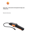
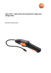
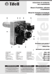
1
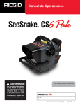
English
Español
OPERATING INSTRUCTIONS
MODEL#–55900
INSTRUCCIONES DE OPERACION
DETECTOR DE REFRIGERANTES
MODELO#–55900
DESIGN CERTIFIED BY INTERTEK TO MEET SAE J2791, J2913 &
EN14624
DETECTS ALL REFRIGERANTS (CFC’s, HCFC’s, H
FC’s & HFO’s including blends)
DISEÑO CERTIFICADO POR INTERTEK PARA CUMPLIR CON SAE J2791, J2913 & EN14624
DETECTA TODOS LOS REFRIGERANTES (CFC’s, HCFC’s. HFC’s, & HFO’s incluyendo mezclas)
www.mastercool.com
1
English
55900
REFRIGERANT LEAK DETECTOR INSTRUCTIONS
PRODUCT OVERVIEW
You have purchased an intelligent electronic leak detector model 55900. At the heart of this leak
detector is a new low power metal oxide gas sensor with superior performance properties such
as lower current consumption and sensor longevity. The new sensor is characterized by high sensitivity and a fast response in detecting the presence of extremely small levels of chlorofluorocarbon gases. For this reason, this sensor was selected and integrated into the 55900 Leak Detector.
A powerful microprocessor automatically selects the best operating condition for the sensor to
ensure optimum performance throughout the life of the product. Upon turn on, the unit momentarily displays the option(s) that were in use when the unit was turned off. This information is
displayed by one or more of the six (6) LEDS. Following this, the sensor is prepared for readiness
in a warm up sequence that lasts a minute or less. The warm up sequence is displayed by six
green vertical LEDs that are extinguished sequentially down until only one green (READY) LED is
lighted. This indicates the end of the warm-up sequence is reached and the unit is ready for use.
The color of the LED indicators indicate the sensitivity range that is selected by the user; green is
for the least sensitive level, yellow for medium sensitivity level and red is for the most sensitive
level. The default sensitivity level of the unit is GREEN upon initial turn-on.
WARNING
This symbol is intended to alert the user of the presence of important operating and maintenance or servicing instructions in the literature accompanying this product.
IMPORTANT GUIDELINES FOR AUTOMOTIVE TECHNICIANS
The following SAE Recommended Practice applies to this instrument and to the use of generally
available leak detection methods to service motor vehicle passenger compartment air conditioning systems.
1. The 55900 leak detector shall be operated in accordance to the equipment manufacturer’s
operating instructions.
2. Leak test with the engine OFF.
3. The AC system shall be charged with sufficient refrigerant to have a gauge pressure of at least
50 PSI (340 Kpa) when not in operation. At ambient pressures below 15˚C (59˚F), leaks may
not be measurable because the pressure may not be reached.
4. A high degree of caution shall be used whenever cleaning agents or solvents are employed to
clean refrigerant lines. The table in this manual identifies the automotive chemicals that can
potentially contaminate the probe tip and the surfaces that are exposed to such chemicals.
Always wipe away dirt or potential false triggering chemicals, using towels or shop air.
5. Visually trace the entire refrigerant system and inspect for signs of air conditioning lubricant
leakage, damage and corrosion on all lines, hoses and components. Each questionable area
shall be carefully checked with the detector probe as well as fittings, hose-to-line couplings,
refrigerant controls, service ports with caps in place, brazed or welded areas and areas around
attachment points and hold-downs on lines and components. If looking for an apparently
larger leak, check first at the Medium 7g/yr or Low 14 g/yr sensitivity setting.
6. Always follow the refrigerant system around in a continuous path so that no area of potential
leaks is missed. If a leak is found, always continue to test the remainder of the system.
7. Recheck service valves with caps removed. Blow shop air over service valve to clear
immediate area and then check with the detector set at 7 g/yr (0.25 oz/yr) Medium sensitivity.
8. Move the detector at a rate of no more than 75 mm/sec (3 in/sec) and as close as possible
to 9.3 mm (3/8 in) from the surface, completely encircling each test position (switch, sensor,
refrigerant tubing connection etc).
9. Slower movement and closer approach of the probe improves the probability of finding a leak.
However, detectors made to meet this standard are required to air sample and detect a leak
from a distance of 9.5mm (3/8 in) distance. Therefore, retest is advised at the most sensitive
setting, when a leak appears to be found, particularly if the probe was in a static position on a
joint or making physical contact with a joint as it was moving. Repeat with a moving probe test
at that location, taking care to maintain a small gap (9.5 mm or 3/8 in) to confirm that the leak
is of a repairable size. Using a 7 g/yr (0.25 oz/yr) Medium sensitivity setting on the detector,
after finding an apparent leak with the 4 g/yr (0.15 oz/yr) High sensitivity setting, may also be
very helpful.
SPECIFICATIONS
Sensing Element:
Tin Oxide Element
Sensor Life: 2000 hours
Refrigerants: Detects all refrigerants (HFC, CFC, HCFC, and blends)
Sensitivity Levels:
HIGH: 0.15 oz/yr (4 g/yr) LED Color: Red
MEDIUM: 0.25 oz/yr (7 g/yr) LED Color: Yellow
LOW:
0.50 oz/yr (14g/yr) LED Color: Green
Response Time: Less than 1 second
Battery: 2 C Alkaline 6000 mAh batteries
Battery Life: 30 Hours
Operating Temperature Range: 0˚F to 120˚F
Weight:1.08 Lbs
“Super Sensitive Function” allows the unit further sensitizing beyond the standard settings for
locating small leaks with gases such as R1234yf and R407C.
2
www.mastercool.com
Probe Properties
• Intelligent tip, with environment sensing
• Flexible 15.5 inch probe length
• Warm-Up Status: Initially, all (6) vertical LED indicators are ON during the
warm-up stage and gradually sequence down to one GREEN LED. The
warm-up sequence takes less than 1 minute.
L
SENSITIVITY:
M
HR
5
LR
4
INT/WT
3
CA
2
1
READY
H
HIGH
6
DETECTION
Display Properties
• Status Indicators: Three (3) vertical LED indicators display the condition
and state of the unit immediately after the unit is turned ON. Status
display duration is approximately 3 seconds.
• LED #6: Identifies a LOW BATTERY condition
• LED #5: Identifies HIGH RANGE (HR) setting is enabled
• LED #4: Identifies LOW RANGE (LR) setting is enabled
LOW
LED Indicators
DEFINITION OF DISPLAY LEGENDS
• BATTERY SYMBOL:
The battery symbol LED #6 is illuminated when the battery reaches a near end of life condition.
• HR: The High Range (HR) should be selected for the detection of hard to detect refrigerant gas, such as R1234yf.
• LR: The Low Range (LR) should be selected for the detection of easy to detect refrigerants, such as R134a.
• INT/WT: Conditions such as excessive air turbulence, or the accidental touching of the probe or by blowing one’s breath at the probe, trigger the
interference (INT/WT) detector.
• CA: The Contaminated Atmosphere (CA) LED will turn on when the
presence of contamination is detected for a period of time.
• READY: Indicates that the unit is ready for use.
KEYPAD FUNCTIONS
• ON/OFF: Turns the unit ON and OFF in a push on and push off sequence.
• PEAK/HR/LR: The PEAK/HR/LR key serves a dual purpose:
(1) To assist the user in locating the “largest leak” in a system with
multiple leaks present.
(2) To enable the user to switch between HR (high range) and LR (low
range) modes.
VOLUME
MUTE
PEAK
HR/LR
H M L
• VOLUME/MUTE: The VOLUME/MUTE key sequentially selects the audible “beep” level forKeypad
the
unit. The choices are: normal, low or mute. All alarms are heard at the maximum level, even in
mute.
• HML (HIGH/MEDIUM/LOW SENSITIVITY): The HML key selects the sensitivity range of the unit.
The color of the LED and the tone of the “beep” change for each sensitivity selected. (High=Red, Medium=Orange, Low=Green)
DISPLAYING THE STATUS SETTINGS
• Depress the ON/OFF key, upon initial turn-on, the unit will momentarily display the status
conditions of the unit. This information will be displayed for approximately 3 seconds. One or
more LED’s will be ON during this brief time to display the following information:
1. If LED #6 is ON, the battery is reaching end-of life and should be replaced before the unit’s
operation is affected.
2. If LED #5 is ON, the unit is in the High Range setting which enables the
unit to detect refrigerants that are difficult to detect. (R1234yf & R407C)
3. If LED #4 is ON, the unit is in the Low Range setting which enables the
unit to detect easy to detect refrigerants. (R134a, R410A, etc.)
DISPLAYING THE WARM-UP STATUS
• All six (6) LEDS turn ON and sequentially become extinguished until only one GREEN LED
remains. At this point, the audible “beep” begins (unless the unit is muted), which is an
indication that the unit is ready for use. This process takes less than 1 minute.
• The unit always defaults to LOW sensitivity upon initial turn-on, as indicated by the
GREEN LED.
CHANGING THE AUDIBLE LEVEL
• The Volume/Mute key enables the user to change the audible “beep” level in a
sequential manner. Successive depression alters the audible level from Normal, Low and
Mute. Upon each depression, the unit visually displays (for less than 1 second) the
selected audible level as follows:
1. In Normal, six LED’s are flashed briefly and the “beep” resumes at the maximum
audible level
2. In Low, three LED’s are flashed briefly and the “beep” resumes at a lower audible level
3. In Mute, only the READY LED stays ON and the audible is muted.
4. The selected audible level will remain stored in the unit unless changed.
CHANGING THE SENSITIVITY
• Depressing the HML key alters the sensitivity of the unit sequentially in the following manner:
1. When in High Sensitivity, the LED #1 (READY) changes to RED
2. When in Medium Sensitivity, LED #1 changes to YELLOW
3. When in Low Sensitivity, LED #1 changes to GREEN.
www.mastercool.com
3
4. During the detection of a leak, all the LED’S follow the color of the READY light.
CHANGING THE OPERATING RANGE FROM HR TO LR
• After the unit has warmed up and the READY indicator is ON, press and hold down the PEAK/
HR/LR key until all LED’s are off. Release the key. The unit will perform a new warm-up
sequence with the new operating range.
REDUCING FALSE LEAK DETECTION
Under Adverse Conditions
To discriminate between false alarms and actual leak detection that may occur in the presence of
excessive air turbulence or accidental touching of the probe tip, the interference detector creates
a momentary interruption in the leak detector for several seconds, resulting in the following:
• When interference is detected, the audible beep stops and the INT/WT light LED #3 and the
READY LED #1 begin to flash briefly. When the unit is ready to resume operation, LED #3
extinguishes, the READY LED #1 turns ON and the audible resumes.
In a Contaminated Environment
When a contaminated area is detected by the unit lasting for a duration of time during a leak
search, the sensor detects the change and will respond in the following manner:
• The READY indicator LED #1 will extinguish, the audible will stop (unless muted) and the INT/
WT indicator LED #3 will turn ON.
• The unit performs a re-calibration for the contaminated environment. When done, the CA
indicator LED #2 turns ON, the READY indicator LED #1 turns ON and the audible returns,
indicating that the unit is ready for use to detect leaks in a contaminated environment.
QUICK START TIPS ON HOW TO FIND LEAKS
A sudden whipping action of the probe or blowing into the sensor may cause the leak detector
to false alarm. Electronic sensors are incorporated into the product to detect such activity and
to reduce and minimize such false alarm. In the event such interference is detected, the LED #3
will begin to flash indicating interference then normal operation can resume after the READY LED
appears.
1. When starting the search for leaks, without a general knowledge of the magnitude of the leak,
set the instrument sensitivity to LOW. The LOW sensitivity will enable the unit to locate
medium as well as large size leaks.
2. Slowly move the probe approximately 3/8 inch (9 mm) above the area of suspected leaks.
Move the probe past the leak to allow the probe to clear if a leak is detected. Do not hold the
probe at the site of a leak. For verification, return the probe to the same area where a leak was
detected.
3. In the event no leaks were found with a LOW sensitivity setting, increase the sensitivity to
MEDIUM and repeat step (2) above.
4. For locating extremely small leaks; 0.1 oz/yr (2.8 grams) or less, the HIGH sensitivity scale
should be used. Due to the extremely small leak size, the tip of the probe should be moved as
close to the surface as possible (without physically touching any object). Physical touching
of an object will be detected by the probe sensors resulting in a brief interruption in the leak
detector. When probing for a leak in an contaminated environment, the sensor will detect the
contaminated area and will automatically adjust for the new conditions.
MAINTENANCE
To Install or Replace the Alkaline Batteries
Remove the battery cover as shown in Figure 1 and remove the existing batteries. It may be
beneficial to turn the unit vertically and shake out both batteries. Install two C size alkaline
batteries with the polarities shown in Figure 1. Re-install the battery cover and secure with the
cover screw.
Cover
Screw for
removing
or securing
the battery
cover
-
+
Figure 1
Replacing the Sensor
To replace the sensor, firmly grasp the flexible probe near the end with one hand and use the
other hand to unscrew the nozzle portion from the threaded probe tip in a counter-clockwise direction. Next, remove the metal washer, the rubber washer and the sensor in that order. Observe
the orientation of the key on the sensor being removed. It would be advisable to replace the filter
inside the nozzle at the same time. To remove the micro-filtration membrane from inside the
nozzle, the assistance of a long thin object such as an o-ring pick or equivalent will be required.
Probe
Rubber Metal
Key Sensor Washer Washer Filter
Nozzle
Figure 2
When installing a new sensor, orient the tab key on the sensor with the keys slot on the probe,
making certain that the 3 pins of the sensor are inserted into the appropriate pins inside the
probe end. Verify that the sensor has been properly inserted into the probe. Next install the
rubber washer as shown in Figure 2, followed by the metal washer. Insert new filter and screw
4
www.mastercool.com
on the nozzle while firmly holding the probe end with the other hand. DO NOT USE ANY TOOLS in
tightening the tip assembly, firmly hand tighten only.
LEAK TEST VIAL
A Leak Test Vial is supplied with your leak detector to verify that the leak detector is operating
correctly.
1. Turn the leak detector ON and wait until the unit completes its warm-up sequence. The READY
LED will be displayed and the audible “beep” will begin, unless muted. Set the sensitivity level
to MEDIUM.
2. Remove the vinyl cap from the vial to expose the small leak hole as shown in Figure 3A below.
DO NOT UNTWIST THE BLACK CAP FROM THE BOTTLE.
Figure 3A
Figure 3B
3. Briefly place the probe tip close to the small hole, as shown in Figure 3B until an audible alarm
is generated. This will be an indication that the unit is operating properly. Reseal the vial with
the previously removed vinyl cap and return to the case.
PRECAUTION!
If the test vial is held in close proximity of the probe tip for an extended period of time, the probe
sensor can saturate. The leak detector will interpret this as a contaminated atmosphere associated with a large refrigerant leak.
This precaution also applies when locating leaks. Refer to Quick Start Tips On How To Find
Leaks, step #2 for further clarification.
If the above precaution is not followed, the CA (contaminated atmosphere) LED may appear on
the display, after a self-calibration process. The unit can be used to detect leaks provided the
READY LED appears on the display. The CA LED indication will eventually disappear when the unit
returns to a non-contaminated environment and undergoes a self-calibration process.
SENSITIVITY TO AUTOMOTIVE CHEMICALS
Due to the chemical similarity between the miscellaneous automotive products listed below and
the chemical properties of refrigerants, some of these chemicals will interfere with the effort of
isolating refrigerant leaks in automobiles. For this reason, the chemicals that the leak detector
responds to should not be present in close proximity of the suspected leak location.
BRAND OR CHEMICAL NAME
RESPONSE
CLEARS IN 20 SEC
Windshield Washer Solvent
Motorcraft Spot & Stain Remover
Motorcraft Metal Brake Parts Cleaner
Motorcraft Penetrating and Lock Lubricant
Motorcraft Break Parts Cleaner
Motorcraft Clear Silicone Rubber
Antifreeze/Coolant
Gunk Liquid Wrench
Motorcraft Natural Citrus Hand Cleaner
Motorcraft DOT3 Brake Fluid
Motorcraft Spray Carburetor Tune-Up Cleaner
Motorcraft Door Latch Grease
Loctite Biodegradable Cleaner & Degreaser
Dexron ATF
Mineral Engine Oil
Silicon Brake Grease
3M Gasket Adhesive
Yes
Yes
Yes
Yes
Yes
Yes
Yes
Yes
Yes
No
Yes
No
Yes
No
No
Yes
Yes
Yes
Yes
Yes
Yes
Yes
Yes
Yes
Yes
Yes
N/A
Yes
N/A
Yes
N/A
N/A
Yes
Yes
REPLACEMENT PARTS
Replacement parts and accessories for the 55900 Leak Detector are available through the same
dealer from whom you purchased the instrument or from Mastercool Inc.
REF. #
1.
2.
3.
4.
5.
6.
7.
DESCRIPTION
Blow Molded Plastic Box
Leak Test Vial
Battery Cover
Sensor
2 “C” Batteries
Sensor Protector
Replacement Filters (3)
MC PART #
55800-PB
55800-VL
55900-BATCOV
55800-SEN
BATTERY “C”
55100-10042
55800-FILTER
www.mastercool.com
5
1
7
2
5
4
3
6
WARRANTY AND LIABILITY
Mastercool Inc. warrants your 55900 Refrigerant Leak Detector to be free from defects of material and workmanship for a period of 2 years from the date of purchase. Mastercool Inc. does not
warrant items that deteriorate under normal use, including batteries, sensor and filter. In addition,
Mastercool Inc. does not warrant this product that shows evidence of misuse. Any evidence of
accident, unauthorized repair or alteration shall also void the stated warranty.
Mastercool’s liability is limited to the product returned to Mastercool, transportation prepaid, not
later than 30 days after the warranty expires and which Mastercool determines to have malfunctioned because of material or workmanship defects. Mastercool’s liability is limited as an option
to repairing or replacing the defective product or part. 6
www.mastercool.com
Español
55900
INSTRUCCIONES DE DETECTOR DE REFRIGERANTES
DESCRIPCION GENERAL DEL PRODUCTO
Usted adquirió un detector inteligente de fugas, modelo ACT825. El corazón de este avanzado
detector de fugas, es un nuevo sensor de gas de óxido de metal de baja potencia, con propiedades de rendimiento superiores como un menor consumo de energía y mayor durabilidad del
sensor. El nuevo sensor se caracteriza por la alta sensibilidad y rápida respuesta en la detección
de presencia de niveles extremadamente pequeños de gases de clorofluorocarbono. Por esta
razón, este sensor fue seleccionado e integrado en el detector de fugas 55900
Un potente microprocesador selecciona automáticamente la mejor condición de funcionamiento
del sensor, garantizando un óptimo rendimiento para el resto de la vida del producto. A su vez,
la unidad momentáneamente muestra la opción (es) que estaban en uso cuando la unidad se
apagó. Esta información se muestra por uno o más de los seis (6) LEDS. Después de esto, el sensor está preparado para la disposición en una secuencia de calentamiento que dura un minuto
o menos. La secuencia de calentamiento se muestra por los seis LEDs verticales verdes que se
desaparecen secuencialmente hacia abajo hasta que sólo un LED verde (LISTO) se enciende.
Esto indica que el ciclo de calentamiento finalizó y la unidad está lista para usar. El color de los
indicadores LED indican el rango de sensibilidad seleccionado por el usuario: el verde para el
nivel de menor sensibilidad, amarillo para el nivel de sensibilidad media y rojo para el nivel de
sensibilidad más alto. El nivel de sensibilidad por defecto de la unidad es VERDE en el encendido
inicial.
ADVERTENCIA
Este símbolo se utiliza para advertir al usuario de la presencia de operaciones importantes y
mantenimiento, o el servicio de instrucciones en la literatura que acompaña este producto
PAUTAS IMPORTANTES PARA LOS TÉCNICOS AUTOMOTORES
La siguiente práctica recomendada SAE, aplica a este instrumento y para el uso de métodos de
detección de fugas en general disponibles para los sistemas de aire acondicionado del compartimiento del vehículo de motor
1. El detector de fugas 55900 deberá ser operado de acuerdo con las instrucciones de
funcionamiento del fabricante del equipo.
2. La prueba de fugas se realizan con el motor apagado.
3. El sistema de aire acondicionado deberá ser cargado con suficiente refrigerante para tener
una presión manométrica de al menos 50 PSI (340Kpa) cuando no esté funcionando. En
presiones ambientales por debajo de 15˚C (59˚F), las fugas no podrán ser medidas debido a
que no se puede alcanzar la presión.
4. Un alto grado de precaución debe ser utilizado siempre que se empleen productos de limpieza
o disolventes para limpiar las líneas de refrigerante. La tabla A de este manual identifica los
productos químicos para automotores que potencialmente pueden contaminar la punta de
la sonda y las superficies que están expuestas a estos productos químicos. Siempre limpie la
suciedad o los posibles disparos químicos no deseados en la superficie. Utilice toallas o aire
de taller.
5. Rastree visualmente todo el sistema de refrigeración y revise si hay signos de fuga del
refrigerante del aire acondicionado, daños y corrosión en todas las líneas, mangueras y
componentes. Cada área cuestionable deberá ser cuidadosamente comprobada con la sonda
detectora, al igual que los accesorios, los acoplamientos de la manguera y los controles de
refrigerante, los puertos de servicio con las tapas en su lugar, zonas soldadas y áreas
alrededor de los puntos de fijación y pisadores en las líneas y componentes. Si busca por
una fuga aparentemente larga, compruebe primero en 7g/año o Bajo 14g/año, en ajustes de
sensibilidad.
6. Siempre siga el sistema del refrigerante por un camino continuo, para que no se pierda una
posible fuga en esa área. Si se encuentra una fuga, siempre continúe con la prueba en el resto
del sistema.
7. Vuelva a revisar el sistema con las capas removidas. Sople con aire de taller sobre la válvula
del sistema para limpiar el área y luego verifique con el detector ajustado en 7g/año (0.25oz/
año). Sensibilidad media.
8. Mueva el detector en un rango no mayor de 75mm/seg (3 pulgadas/seg) y lo más cerca
posible a 9.3mm (3/8 pulgadas) de la superficie, rodeando por completo cada posición de
prueba (interruptor, sensor, conexión del tubo del refrigerante, etc).
9. Movimientos lentos y un mayor acercamiento de la sonda mejora la probabilidad de encontrar
una fuga. Sin embargo, los detectores creados para cumplir con esta norma requieren que
la muestra de aire y la detección de una fuga sea a una distancia de 9.5mm (3/8 pulgadas).
Por lo tanto, una segunda prueba es sugerida incluso en el ajuste más sensible, cuando una
fuga parece encontrarse, particularmente si la prueba fue en una posición quieta en un punto
de contacto o haciendo contacto físico con uno de los puntos de conexión al momento que
se movía. Repita con una prueba de movimiento en la locación, teniendo cuidado de mantener
una pequeña distancia (9.5mm o 3/8 pulgadas) para confirmar que la fuga es de un tamaño
reparable. Usando una sensibilidad media en los ajustes del detector de 7gr/año (0.25 oz/año),
luego de encontrar una aparente fuga, con 4g/año(0.15 oz/año) en los ajustes de sensibilidad
alta, puede ser de gran ayuda.
ESPECIFICACIONES
Elemento Sensible:
Vida del sensor:
Elemento de Dióxido de Estaño.
2000 horas.
www.mastercool.com
7
Refrigerantes:
Niveles de Sensibilidad:
Tiempo de Respuesta:
Batería:
Vida de la Batería:
Rango de temperatura:
Peso:
Detecta todos los refrigerantes (HFC, CFC, HCFC y derivados).
ALTA: 0.15 oz/yr (4g/año)
Color LED: ROJO
MEDIA: 0.25 oz/yr (7g/año).
Color LED: AMARILLO
BAJA: 0.50 oz/yr (14g/año).
Color LED: VERDE
Menos de un segundo.
2 Baterías alcalinas tamaño C, 6000 mAH.
30 horas
0 a 120˚F
1.08 Lbs
“Función súper sensible “ permite que la unidad sea más sensible de los ajustes estándar para la
localización de pequeñas fugas de gases como R1234yf y R407C.
Propiedades de la sonda
• Punta inteligente, con sensor de ambiente
• Longitud de la sonda flexible de 15,5 pulgadas
Indicadores de estado
L
SENSITIVITY:
6
HR
5
LR
4
INT/WT
3
CA
2
1
READY
M
H
HIGH
DETECTION
Propiedades de pantalla
• Indicadores de estado: Tres (3) indicadores verticales LED muestran la
condición y el estado de la unidad inmediatamente después de que la
unidad está encendida. La visualización del estado es de
aproximadamente 3 segundos.
• LED # 6: Indica batería baja
• LED # 5: Indica que el rango alto (RA) está activado
• LED # 4: Indica que el rango bajo (RB) está activado
• Estado de Calentamiento:Inicialmente, todos (6)los indicadores verticales
LED están encendidos durante la fase de calentamiento desaparecen
secuencialmente hacia abajo hasta que sólo un LED verde (LISTO) se
enciende. La secuencia de calentamiento tarda menos de 1 minuto
LOW
DEFINICION DE LAS LEYENDAS DE PANTALLA
• Símbolo de batería: El símbolo de la batería LED # 6 se ilumina cuando la batería se acerca al final de su ciclo de vida.
• RA: El rango alto (RA) debe ser seleccionado para la detección de gases refrigerantes difíciles de detectar como R123yf
• RB: El rango bajo (RB) debe ser seleccionado para la detección de gases refrigerantes fáciles de detectar como R134a
• LED # 4: Indica que el rango bajo (RB) está activado
• Estado de Calentamiento:
Inicialmente, todos (6)los indicadores verticales LED están
encendidos durante la fase de calentamiento desaparecen secuencialmente hacia abajo hasta que sólo un LED verde (LISTO) se enciende. La secuencia de calentamiento tarda menos de 1 minuto
• INT/WT: Las condiciones tales como la turbulencia del aire excesivo, o el
contacto accidental de la sonda o soplar la sonda activa el
detector de interferencia
• AC: La Atmósfera Contaminada (AC) LED se encenderá cuando se
detecta la presencia de contaminación por un período de tiempo.
• LISTO: Indica que la unidad está lista para su uso.
Teclado
FUNCIONES DEL TECLADO
• ON/OFF: Enciende y apaga la unidad, presionando ON y OFF.
VOLUME
MUTE
PEAK
HR/LR
• Peak/HR/LR: La tecla PICO / RA / RB tiene un doble propósito: (1) Para
ayudar al usuario en la localización de la “fuga más grandes” en un
H M L
sistema con múltiples fugas presentes. (2) Para que el usuario pueda
cambiar entre RA (Rango alto) y RB (Rango Bajo) modos.
• VOLUMEN/MUTE: La tecla volumen/mute (silencioso) selecciona el nivel de sonido del “bip”
para la unidad. Las opciones son: normal, baja o silencioso. Todas las alarmas se escuchan en
el nivel máximo, incluso en mudo.
• HML (alta/media/baja sensibilidad): La tecla HML selecciona el rango de sensibilidad de la
unidad. El color del LED y el tono “pitido” para cada sensibilidad seleccionada cambia. (Alto =
rojo, media = Naranja, bajo = verde)
VISUALIZACION DE AJUSTES DE ESTADO
• Presionar la tecla ON / OFF, al encendido inicial, la unidad mostrará momentáneamente el
estado de la condición de la unidad. Esta información se mostrará durante unos 3 segundos.
uno o más LEDs se encenderán durante este breve tiempo para mostrar la siguiente
información:
1. Si el LED # 6 está en ON (encendido), la batería está llegando al final de su ciclo de vida y
debe ser reemplazado antes que la operación de la unidad se vea afectada.
2. Si LED # 5 está en ON (encendido), la unidad está en el ajuste de rango alto que permite a
la unidad detectar refrigerantes que son difíciles de detectar. (R1234yf y R407C)
3. Si LED # 4 está en ON (encendido), la unidad está en el ajuste de rango bajo que permite a la
unidad detectar refrigerantes que son fáciles de detectar (R134a, R410A, etc.)
VISUALIZACION ESTADO DE CALENTAMIENTO
• Los (6) LEDs se encienden y desaparecen secuencialmente hasta que sólo un LED verde queda
encendido. En este punto, el “bip” audible comienza a sonar (a menos que la unidad este
silenciada) indicando que la unidad esta lista para usar. Este proceso toma menos de un
minuto.
• Siempre la unidad por defecto va a estar en el nivel de sensibilidad bajo en el encendido inicial.
8
www.mastercool.com
Indicado con el LED verde.
MODIFICACIÓN DEL NIVEL SONORO
• La tecla Volumen / Mute permite al usuario cambiar el nivel de sonido del “bip” de manera
secuencial. Depresión sucesiva altera el nivel sonoro de Normal, Bajo y Silencio. A cada
depresión, la unidad muestra visualmente (por menos de 1 segundo) el nivel audible
seleccionado de la siguiente manera:
1. En Normal, seis LED parpadean brevemente y el “bip” se reanuda en el máximo nivel audible
2. En baja, tres LED parpadean brevemente y el “bip” se reanuda en un nivel inferior audible
3. En silencio, sólo el LED LISTO permanece encendido y el audible se silencia.
4. El nivel audible seleccionado permanecerá almacenado en la unidad a menos que se
modifiquen.
MODIFICACION DE LA SENSIBILIDAD
• Presionando la tecla AMB altera la sensibilidad de la unidad de manera secuencial de la
siguiente manera:
1. Cuando esté en alta sensibilidad, el LED # 1 (listo) cambia a ROJO
2. Cuando esté en la sensibilidad media, LED # 1 cambia a amarillo
3. Cuando esté en la sensibilidad baja, LED # 1 cambia a verde
4. Durante la detección de una fuga, todos los LED siguen el color de la luz LISTO.
CAMBIO DEL RANGO DE OPERACIÓN DE RA A RB
• Después de que la unidad se haya calentado y el indicador Listo está encendido, presione y
mantenga presionada la tecla PICO/ RA / RB todos los LED están apagados. Suelte la tecla. La
unidad realizará una nueva secuencia de calentamiento con el nuevo rango de operación.
REDUCCIÓN DE DETECCIÓN DE FUGAS FALSO
Bajo condiciones adversas
Para discriminar entre falsas alarmas y la detección de fugas actuales que pueden ocurrir en
la presencia de turbulencias de aire excesiva o contacto accidental de la punta de la sonda, el
detector de interferencia crea una interrupción momentánea en el detector de fugas durante
varios segundos, dando como resultado lo siguiente:
• Cuando se detecta interferencias, los “bip” audibles se detienen y la luz LED #3 INT / WT y el
LED LISTO # 1 comienzan a parpadear brevemente. Cuando la unidad está lista para reanudar
la operación, el LED # 3 se apaga, el LED LISTO # 1 se enciende (ON) y los “bip” audibles se
reanudan.
En un ambiente contaminado
Cuando un área contaminada se detecta por la unidad durante una búsqueda de fugas, el sensor
detecta el cambio y responderá de la siguiente manera:
• El indicador LED listo # 1 se apagará, el “bip” audible se detendrá (a no ser que este
silenciado) y el indicador INT/WT LED # 3 se encenderá.
• La unidad realiza una re-calibración para el ambiente contaminado. Cuando haya terminado,
el indicador LED # 2 AC se enciende (ON), el indicador LED LISTO # 1 se enciende (ON) y los
“bip” audibles vuelven, lo que indica que la unidad está lista para detectar fugas en un
ambiente contaminado.
CONSEJOS DE INICIO RÁPIDO SOBRE CÓMO ENCONTRAR FUGAS
Una acción de movimiento repentina de la sonda o de soplado en el sensor puede hacer que
el detector de fugas de una falsa alarma. Los sensores electrónicos están incorporados en el
producto para detectar dicha actividad y para reducir y minimizar tales falsas alarmas. En el caso
de que se detecte una interferencia, el LED # 3 comenzará a parpadear indicando interferencia
entonces la operación normal puede reanudarse después de que aparezca el LED LISTO.
1. Al iniciar la búsqueda de fugas, sin un conocimiento general de la magnitud de la fuga, ajustar
la sensibilidad del instrumento en BAJA. La BAJA sensibilidad permitirá a la unidad localizar
fugas medianas así como fugas de gran tamaño.
2. Mueva lentamente la sonda aproximadamente 3/8 de pulgada (9 mm) por encima de la zona
con posibles fugas. Mueva la sonda más allá de la fuga para permitir que la sonda se disipe si
se detecta una fuga. No mantenga la sonda en el lugar de la fuga. Para la verificación, devuelva
la sonda a la misma zona donde se detectó la fuga.
3. En caso de que no se encuentren fugas con un ajuste de sensibilidad bajo, aumente la
sensibilidad a MEDIO y repita el paso anterior (2).
4. Para localizar figas extremadamente pequeñas fugas; 0,1 oz / año (2,8 gramos) o menos, la
escala de sensibilidad ALTA debe ser utilizada. Debido al tamaño extremadamente pequeño
de fugas, la punta de la sonda debe ser movida lo más cerca posible de la superficie (sin tocar
físicamente cualquier objeto). El contacto físico de un objeto será detectado por los sensores
de la sonda teniendo como resultado una breve interrupción en el detector de fugas. Cuando el
sondeo de una fuga es es un ambiente contaminado, el sensor detectará el área contaminada y
se ajustará automáticamente para las nuevas condiciones.
MANTENIMIENTO
Instalar o reemplazar las baterías alcalinas
Remueva la tapa de la batería, como se muestra en la figura 1 y extraiga las baterías existentes.
Puede ser beneficioso voltear la unidad en posición vertical y agitarla hasta que salgan las dos
baterías. Instale dos baterías alcalinas tamaño D con las polaridades como se muestran en la
figura 1. Coloque nuevamente la tapa y asegure con el tornillo se cierre.
www.mastercool.com
9
figura 1
Reemplazo del sensor
Para reemplazar el sensor, sujete con firmeza la sonda flexible cerca del final y con la otra mano
para desenroscar la parte de la boquilla de la punta de la sonda, con rosca en sentido contrario
a las agujas del reloj. Luego, quite la arandela de metal, la arandela de goma y el sensor, en este
orden. Observe que la orientación de la llave en el sensor haya sido removida. Es aconsejable
reemplazar el filtro dentro de la boquilla al mismo tiempo. Para quitar la membrana de micro
filtración desde el interior de la boquilla se requiere un objeto largo y delgado, como un extractor
de juntas tóricas o un equivalente.
figura 2
Cuando instale un Nuevo sensor, oriente la tecla de tabulación en el sensor con la ranura de
las teclas en la sonda, asegurándose que los 3 pin del sensor son insertados en los pasadores
adecuados en el interior del extremo de la sonda. Verifique que el sensor haya sido insertado
correctamente dentro de la sonda. Luego instale la arandela de goma como se muestra en la
figura 2 seguido por la arandela de metal. Inserte el nuevo filtro y enrosque la boquilla mientras
sujeta firmemente el extremo de la sonda con la otra mano.
PRUEBAS DE FUGAS EN VIAL
Una prueba de fugas Vial se suministra con su detector de fugas para comprobar que el detector
de fugas está funcionando correctamente.
1. Encienda el detector de fugas y espere hasta que la unidad complete su secuencia de
calentamiento. El LED LISTO se visualizará y el sonido de “bip” se iniciará, a no ser que esté
silenciado. Ajuste el nivel de sensibilidad a MEDIO.
2. Retire la tapa del vinilo del vial para exponer el agujero de fuga pequeña, como se muestra en
la Figura 3A a continuación. NO DESENROSQUE LA TAPA NEGRA DE LA BOTELLA.
figura 3A
figura 3B
3. Coloque suavemente la punta de la sonda cerca del agujero pequeño, como se muestra en
la figura 3B hasta que se genere una alarma audible. Esta será una indicación de que la
unidad está funcionando correctamente. Volver a sellar el vial con la tapa de vinilo eliminado
previamente y volver al caso.
PRECAUCIÓN!
Si la prueba de fuga vial se mantiene en una proximidad estrecha de la punta de la sonda
durante un período prolongado de tiempo, el sensor de la sonda se puede saturar. El detector
de fugas lo interpretará como un ambiente contaminado asociado con una fuga de refrigerante
grande. Esta precaución se aplica también al localizar fugas. Consulte la Guía de CONSEJOS
DE INICIO RÁPIDO SOBRE CÓMO ENCONTRAR FUGAS, paso # 2 para más aclaraciones. Si la
precaución anterior no se sigue, puede aparecer el LED de AC (atmósfera contaminada) en la
pantalla, después de un proceso de auto-calibración. La unidad se puede utilizar para detectar
fugas siempre que aparezca el LED LISTO en la pantalla. El indicador LED AC eventualmente
desaparecerá cuando la unidad vuelve a un ambiente no contaminado y se somete a un proceso
de auto-calibración.
SENSIBILIDAD A LOS QUÍMICOS DE AUTOMOTORES
Debido a la similitud química entre los diversos productos de automoción en listados a continuación y las propiedades químicas de los refrigerantes, algunos de estos productos químicos
interfieren con el esfuerzo de aislar la fuga del refrigerante en los automóviles. Por esta razón, los
químicos al que el detector de fugas responde, no deben estar presentes en las proximidades de
la zona donde se sospecha que hay una fuga.
MARCA O NOMBRE QUIMICO
Windshield washer Solvent (Líquido para lavar el parabrisas)
Motorcraft® Spot and Stain Remover (Motorcraft® Spot y
Quitamanchas)
Motorcraft® Metal Brake Parts Cleaner (Motorcraft® Limpiador de piezas de frenos de metal)
10
www.mastercool.com
Respuesta Limpia en 20 seg
Yes
Yes
Yes
Yes
Yes
Yes
Motorcraft® Penetrating and Lock Lubricant (Motorcraft®
Penetrante y bloqueo lubricante)
Motorcraft® Brake Parts Cleaner (Motorcraft® Limpiador de
piezas de frenos)
Motorcraft® Clear Silicone Rubber (Motorcraft® Limpiador
caucho de silicona)
Antifreeze/Coolant (Anticongelante/Refrigerante)
Gunk® Liquid Wrench
Motorcraft® Natural Citrus Hand Cleaner (Limpiador cítrico
natural para manos)
Motorcraft DOT 3 brake Fluid (DOT 3 Líquido de frenos)
Motorcraft® Spray Carburetor Tune-up Cleaner (limpiador de
carburador en espray )
Motorcraft® Door Latch Greased (Motorcraft® grasa para
cierre de puerta)
Loctite Biodegradable Cleaner & Degreaser (Loctite Limpiador
Biodegradable y Desengrasante)
Dextron ATF, heated ( Dextron ATF, climatizado)
Mineral engine oil ( aceite mineral de motor)
Grasa de silicona para freno
3M Gasket Adhesive (3M Junta Adhesiva)
Yes
Yes
Yes
Yes
Yes
Yes
Yes
Yes
Yes
Yes
Yes
Yes
Yes
No
Yes
N/A
Yes
Yes
No
N/A
No
No
N/A
N/A
PIEZAS DE REPUESTO
Las piezas de repuesto y accesorios para el detector de fugas 55900, están disponibles a través
del mismo vendedor a quién le compro el instrumento.
REF. #
1.
2.
3.
4.
5.
6.
7.
DESCRIPCION
MOLDEADO POR SOPLEADO CAJA PLASTICA
PRUEBA VIAL DE FUGA
TAPA DE LA BATERIA
SENSO
2 BATERIAS “C”
PROTECTOR DE SENSOR
FILTRO DE REPUESTO (3)
MC PARTE #
55800-PB
55800-VL
55900-BATCOV
55800-SEN
BATTERY “C”
55100-10042
55800-FILTER
1
7
2
5
4
3
6
GARANTIA Y RESPONSABILIDAD
Mastercool garantiza su Detector de Fugas 55900 contra defectos de material y fabricación por
un periodo de 2 años a contar de la fecha de su compra. Mastercool no cubre la garantía de
este producto causado por su uso normal, incluyendo baterías sensores o filtros. Adicionalmente
Mastercool no garantiza este producto que muestre evidencias de mal uso. Cualquier evidencia
de accidente, reparación no autorizada o alteración cancela automáticamente esta garantía.
La responsabilidad de Mastercool está limitada al producto que se devuelve a Mastercool,
transporte pre-pagado, no más allá de 30 días después de que la garantía haya vencido y que
Mastercool haya determinado que el defecto se debe al material y/o fabricación. La responsabilidadde Mastercool está limitada a la opción de reparar o reemplazar el producto o parte.
www.mastercool.com
11
USA
PH (973) 252-9119
Belgium
TELEFON +32 (0) 3 777 28 48
Brasil
TELEFONE +55 (11) 4407 4017
12
www.mastercool.com
55900-INT-INST