1
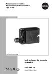
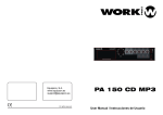
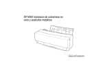
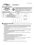
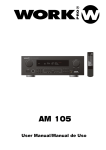
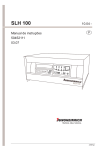
Equipson, S.A.
www.equipson.es
[email protected]
WPE 500
User Manual / Manual de uso
MODEL WPE-500
MULTI-EFFECT PROCESSOR
PROCESADOR MULTIEFECTOS
ENGLISH
Page 1
CASTELLANO
Página 14
ATTENTION!
All WORK products are carefully packed and designed to protect the units from rough handling
before shipping out from the factory. Examine your good before using, to ensure no damage during transportation.
Any damage claim should be inform & notify to relative dealer within 14 days of good received. The dealer
will not except failing of such. The consignee must make all shipping claims.
The WPE-500 fits into a standard 19" rack unit of space (1 3/4" ). Allow at least an additional 4" depth for the
connectors on the back panel. Be sure that there is enough air space around the unit for cooling and ventilation.
DO NOT place the WPE-500 on high temperature devices like power amplifiers etc. to avoid overheating.
Using a main cable and a standard IEC receptacle makes the main connection of the WPE-500. It meets all of the
international safety certification requirements.
Please make sure that all units have a proper ground connection. For your own safety, do not remove the ground
connection within the unit or at the supply, or fail to make this connection at all.
Before switching voltage for local supply requirement, correct fuse type and rate must be installed. Refer to
Appendix, 5.1 for specifications.
This machine is only intended for qualified personnel to operate & install. Do not attempt to repair and service
yourself but referred to qualified technical service personnel. The user must have sufficient electrical contact
to earth. Electrostatic charges might affect the operation of the WPE-500.
NOTICE: Before switching voltage for local supply requirement, correct fuse type and rate must be installed.
When the power supply is 230V, fuse is 125mA; and the power supply is 115V, fuse is changed
to 250mA. The switch is preseted to 230V in the factory.
CAUTION
115V
230V
230V
THE POWER
SUPPLY CORD
SHOULD BE
DISCONNECTED
BEFORE
CHANGING
THE VOLTAGE
SELECTOR
This symbol on the product or on its packaging indicates that this product
shall not be trated as household waste. Instead it shall be handed over to
the applicable collection point for the recycling of electrical an electronic
equipment. By ensuring this product is disposed of correctly, you will help
prevent potential negative consequences for the environment and human
health, which could otherwise be caused by inappropriate waste handling
of this product. The recycling of amterials will help to conserve natural
resources. For more detailed information sabout recycling of this product,
please contact your local city office, your household waste disposal service
or the shop where you purchased the product.
WPE 500
MULTI EFFECT
USER MANUAL/ MANUAL DE USO
PAG. 26
WPE 500
MULTI EFFECT
USER MANUAL/ MANUAL DE USO
PAG. 1
Tab 5.2.5
MODEL WPE-500
NAME
MIX(%)
DEl(ms)
DEPTH(%) RATE(%)
FB(%)
28
SLOW CHORUS
61
16
29
14
5
29
MEDIUM CHORUS
61
16
45
8
0
30
FAST CHORUS
61
8
16
26
0
31
SPECIA CHORUS
61
74
100
2
37
32
SLOW LESLIE
45
24
45
8
20
33
FAST LESLIE
33
24
4
81
20
3 band parametric equalizer
34
MEDIUM FLANGER
61
24
27
4
85
48 kHz sampling rate
35
77
32
53
6
77
61
74
69
6
29
61
100
29
12
45
48 Factory preset effects, 48 user editable programs & memories
768 types of effects, suitable for all environments
43
Soft touch power on operation
44
16x2 back light LCD display
BRIGHT FLANGER
CHORUS&M.DELAY
CHORUS&L.DELAY
Tab 5.2.6
Full MIDI capability allows real time parameter control and program selection
NAME
REV
Internal power supply design for professional application
REV
TIME(s)
MIX(%)
High quality components and exceptionally rugged construction ensures durability
H FREQ(%)L FREQ(%) REV
REV
DEL
DEL
DEL
REV
REV
DENS(%)LPF(kHz) MIX(%) TIME(ms) FB(%)
37
DELAY&REVERB
45
1.1
91
100
37
8
45
1000
0
38
RE.DELAY&REVERB
45
1.1
91
100
37
8
45
1000
37
Tab 5.2.7
NAME
REV
MIX(%)
REV H FREQ(%) L FREQ(%) REV REV
CHO
CHO
CHO
CHO
CHO
TIME(s)
DENS(%)
LPF(kHz) MIX(%) DEL(ms) DEPTH(%)RATE(%)FB(%)
REV
REV
39
CHORUS&M.REV.24
2.5
75
100
0
12.5
61
32
69
8
20
40
CHORUS&L.REV. 24
3.4
75
100
0
12.5
61
40
16
20
0
FLG
FLG
FLG
FLG
Tab 5.2.8
NAME
REV
MIX(%)
REV
H FREQ(%)L FREQ(%) REV
TIME(s)
REV
REV
REV
FLG
DENS(%)LPF(kHz) MIX(%) DEL(ms) DEPTH(%) RATE(%) FB(%)
41
FLANGER&M.REV.45
2.5
75
100
0
12.5
61
24
24
8
24
42
FLANGER&L.REV. 45
3.4
75
100
0
12.5
77
32
53
6
37
Tab 5.2.9
NAME
REV
MIX(%)
WPE 500
MULTI EFFECT
USER MANUAL/ MANUAL DE USO
PAG. 2
REV
TIME(s)
H FREQ(%) L FREQ(%)
REV
REV
REV
REV
DIST
DIST DIST
DENS(%) LPF(kHz) DEPTH(%) LPF(%)
45
L.DISTORTION&REV.
20
2.1
87
6
24
8
46
M.DISTORTION&REV.
20
1.8
87
6
24
8
37
45
ON
47
H.DISTORTION&REV.
20
3.4
87
6
24
8
100
37
ON
WPE 500
MULTI EFFECT
USER MANUAL/ MANUAL DE USO
10
PAG. 25
45
ON
5.2 Configuracion pot defecto
TABLE OF CONTENTS
Tab 5.2.1
NAME
MIX(%) TIME(s) H FREQ(%)L FREQ(%)DENS(%) PLF(kHz)
1. Description
4
2. Control panel
5
2.1 Menu Functions
5
01
CATHEDRAL 1
70
8
70
100
30
4
02
CATHEDRAL 2
70
6
70
100
30
4
03
MEDIUM PLATE
70
3
60
100
50
2
2.2 Function buttons & Program Knobs
5
04
BRIGHI PLATE
70
4
70
100
50
2
2.3 Combination Button
7
05
SMALL HALL
70
1
50
40
30
2.5
06
07
70
2
70
90
30
2.5
2.4 Rear panel
MEDIUM HALL
7
LARGE HALL
33
7.8
91
100
37
4
08
ROOM 1
8
2.7
91
100
37
4
3. MIDI Control
37
09
10
ROOM2
37
4.7
69
100
37
2.5
MED.STUDIO
2.4
75
100
100
2.5
4. Application
20
9
11
12
LARGE CONCERT
20
4.6
75
100
100
2.5
4.1 Connecting Aux bus with WPE-500
9
MED.CONCERT
20
2.7
87
100
100
2.5
4.2 Connecting MIDI system with WPE-500
9
13
14
LARGE CONCERT
20
6.2
87
100
100
2.5
20
2.7
75
100
100
2.5
15
VOCAL
30
2.6
87
100
100
2.5
16
PERCUSSION
20
5.4
87
100
100
2.5
STAGE
5. Appendix
10
5.1 Effect lists
10
5.2 Preset lists
11
5.3 Technical Specifications
13
Tab 5.2.2
NAME
MIX(%) TIME(ms) FB(%)
17
DELAY
45
560
26
18
SHORT DELAY
45
70
0
19
MEDIUM DELAY
45
470
0
20
MULTI TAP DELAY
45
380
16
21
PANING DEALY
45
1000
0
22
ECHO
50
140
22
Tab 5.2.3
NAME
MIX(%) TIME(ms) DENS(%) LPF(kHz)
23
SHORT GATE REV.
37
130
24
10
24
MED.GATE REV.
18
530
37
10
25
LONG GATE REV.
18
1000
37
10
26
REVERSE GATE
18
460
37
10
27
L TO R GATE
16
1000
37
10
Tab 5.2.4
NAME
MIX(%) LEFT COAR(%) RIGHT COAR(%) L TUNE(%) R TUNE(%)
36
PITCH
100
-12
+12
0
0
48
PITCH&DELAY100
-12
-12
0
0
WPE 500
MULTI EFFECT
USER MANUAL/ MANUAL DE USO
DEL TIME(ms)
DEL FB(%)
10
380
PAG. 24
0
21
WPE 500
MULTI EFFECT
USER MANUAL/ MANUAL DE USO
PAG. 3
5.Apéndice
1. Introduction
5.1 Tabla de Efectos
WPE-500 is a multi-effects processor designed with flexibility & user friendly for all venues & events.
Available 48 factory preset effects for instant operation (P1 ~P48). Also available 48 effects for user program
(U1~U48). All parameters are editable with memory function, included:
Effect Mode
01
02
03
04
05
06
07
08
09
10
11
12
13
14
15
16
17
18
19
20
21
22
23
24
25
26
27
28
29
30
31
32
33
34
35
36
37
38
39
40
41
42
43
44
45
46
47
48
(1) Reverb parameter:
"MIX"- Reverb effect-mixing level
"TIME"- Reverberation Time
"H FREQ REV"- High frequency Reverberation ratio
"L FREQ REV"- Low frequency Reverberation ratio
"DENS"- Reverb density
"PLF"- Pre lowpass filter
(2) Delay group parameter:
"MIX"- Delay mixing level
"TIME"- Delay Time
"FB"- Feedback
(3) Chorus / Flanger parameters:
"MIX"- Chorus / Flanger mixing level
"DEL"- Chorus / Flanger delay time
"DEPTH"- Chorus / Flanger depth
"RATE"- Chorus / Flanger rate
"FB"- Chorus / Flanger feedback
(4) Noise/Gate parameters:
"GATE MIX"- Noise Gate mixing level
"GATE TIME"- Noise/Gate Time
"GATE DENS"- Noise / Gate Density
"GATE PLF"- Gate pre lowpass filter
(5) Pitch parameters:
"PITCH MIX"- Pitch mixing level
"L COARSE"- Left channel detune
"R COARSE"- Right channel detune
"L FINE TN"- Left channel fine tuning
"R FINE TN"- Right channel fine tuning
"DEL TIME"- Delay time
"DEL FB"- Delay feedback
(6) Distortion parameters:
"DISTORTION ON"- ON / OFF Distortion select
"DIST DEPTH"- distortion depth
"DIST LPF"- Distortion Low Pass Filter
(7) Delay + Reverb
(8) Chorus + Reverb
(9) Flanger + Reverb
(10) Chorus + Delay
(11) Distortion + Reverb
(12) Pitch + Delay etc. combine effect parameters.
WPE 500
MULTI EFFECT
USER MANUAL/ MANUAL DE USO
PAG. 4
WPE 500
MULTI EFFECT
Name
CATHEDRAL 1
CATHEDRAL 2
MEDIUM PLATE
BRIGHT PLATE
SMALL HALL
MEDIUM HALL
LARGE HALL
ROOM 1
ROOM 2
MED.STUDIO
LARGE STUDIO
MED.CONCERT
LARGE CONCERT
STAGE
VOCAL
PERCUSSION
DELAY
SHORT DELAY
MEDIUM DELAY
MULTI TAP DELAY
PANNING DEALY
ECHO
SHORT GATE REV.
MED.GATE REV.
LONG GATE REV.
REVERSE GATE
L TO R GATE
SLOW CHORUS
MEDIUM CHORUS
FAST CHORUS
SPECIAL CHORUS
SLOW LESLIE
FAST LESLIE
MEDIUM FLANGER
BRIGHT FLANGER
PITCH
DELAY&REVERB
RE.DELAY&REVERB
CHORUS&M.REV.
CHORUS&L.REV.
FLANGER&M.REV.
FLANGER&L.REV.
CHORUS&M.DELAY
CHORUS&L.DELAY
L.DISTORTION&REV.
M.DISTORTION&REV.
H.DISTORTION&REV.
PITCH&DELAY
婬晊奀睿髦砒
磁釭睿笢脹晊奀
笢脹囮淩睿髦砒
USER MANUAL/ MANUAL DE USO
PAG. 23
4. APLICACIONES
2. CONTROL PANEL ELEMENT
4.1 Usando WPE 500 como bus auxiliar
Usando el WPE 500 como bus auxiliar de su consola de mezclas, puede alimentar la señal de un canal,
varios o algunos de todos los canales de su consola dentro del WPE 500, p.e. En varios sonidos de batería es
posible aplicar reverb a uno de los ellos y reducir la intensidad del resto, para usarlo como bus auxiliar, la
unidad debe ser conectada como sigue:
Fig 2.1: WPE-500 Front Control Panel
There are 6 function buttons for control & editing purpose and 1 LCD display screen in the WPE-500 Front Panel.
In L
Out
In R
AUX
1(&2)
2.1 Menu Function Display
1
AUX
Retum
CLIP
L
PO1:
CLIP
CATHEDRAL1
2
REV MIX:33%
R
3
Fig.2.2: Menu Function Display
(1) 2 LED light for left/right input/output indication
(2) 1st line to display effect modes
(3) 2nd line to display parameters
(4) " : " blinking to indicate editable program is activated
Fig.4.1: Cableando bus auxiliar
4.2 Usando WPE 500 en un sistema MIDI
Con el interface MIDI incorporado, el WPE 500 puede ser integrado dentro de cualquier sistema MIDI
Puede transmitir y recibir cambios de programa y control de información via MIDI desde un secuenciador
u otro dispositivo MIDI. Cablee y configure el WPE 500 como se muestra abajo:
2.2 Function Buttons & Program Knob
1
4
PROGRAM
LOCK
BYPASS
PARAM
EQ
STORE
RESET
MIDI
5
7
MIDI In
3
MIDI Thru
MIDI In
8
POWER
I
0
Fig.2.3: Function & Program Buttons
MIDI Out
MIDI Out
6
2
MIDI Out
MIDI
Sequencer
DIGISYNTHETIC
MIDI In 1
(1) To edit parameter values, turning clockwise to increase and anti-clockwise to decrease values, "SV" blinking
to indicate edited parameter is in progress for memory.
(2) PROG- Press this button to select program and LCD screen will display program effect (as Fig. 2.4), and
this " : " symbol blinks to indicate program from P1-P48 is ready for use. Press this button again to select
USER PROGRAM EFFECT (as Fig 2.5). User is able to select any program memory from U1-U48 by
turning Knob.
CLIP
L
MIDI In 2
PO1:CATHEDRAL1
CLIP
R
FIG.4.2:Conectando el WPE 500 via MIDI a un secuenciador/ordenador o un teclado.
WPE 500
MULTI EFFECT
USER MANUAL/ MANUAL DE USO
PAG. 22
REV MIX:33%
Fig.2.4: Factory preset Default program
WPE 500
MULTI EFFECT
USER MANUAL/ MANUAL DE USO
PAG. 5
(3) PARAM-PARAMETER BUTTON
Press this button to display second line information of present program parameter. " : " blinks to allow
parameter adjustment by Knob. Repeat pressing this button to select different parameter items and
turning Knob to increase or decrease value. While "SV" blinks and display on top right or bottom right
screen means parameter has been edited and reminding user to save changes or not. Press button 7 (STORE)
to store and save edited value. Example: To edit "P 02" entire parameter value. Press this button shortly to
show "REV MIX: 50%" on second line of LCD Screen. " : " symbol will blink, turning Knob clockwise
to increase "MIX : 50%" to "MIX : 70%", hold "PARAM" button shortly again to display second line
information with "REV TIME: 7.0s". " : " symbol blink, turn Knob anti-clockwise to decrease "7.0s"
to "6.8s". Press " PARAM" button, "REV H FREQ" will display in second line, " : " symbol blinks, turning
Knob clockwise or anti-clockwise to increase or decrease parameter value respectively.
CLIP
L
UO2:CATHEDRAL2
CLIP
R
REV MIX:60%
Fig.2.5: USER PROGRAM
(4) LOCK- First hold this button for longer seconds to display first line information with the last " " symbol,
this shows Function Button is in LOCK mode situation ( as Fig 2.6). Other than this button, the rest of the
nd
st
button is not functioning. 2 time holding this button for longer seconds to disable the 1 line last " " symbol,
this means the LOCK mode function is disable, all buttons resume to its original function.
CLIP
L
2.4 Panel trasero
4
5
OUT
THRU
IN
IN: REPLACE WITH SAME TYPE FUSE AND RATING
ATTENTION: RISK OF ELECTRIC SHOCK
DO NOT OPEN THE COVER OR BACK
CHINA:
160-250VAC T100mA
DIGISYNTHETIC PLUS MODEL DSP PDAC
CONCEIVED AND DESIGNED BY DIGISYNTHETIC CHINA
ALL INPUTS & OUTPUTS
FULLY BALANCED
TIP/PIN2 +
RING/PIN3 SLEEVE/PIN1
INPUT LEVEL
20dB
MIDI
INPUT LEVEL
20dB
+4dB
2
SERIAL NUMBER
1
+4dB
2
3
1
3
DATE CODE
OUTPUTS 2
INPUTS 2
OUTPUTS 2
INPUTS 1
(1)NIVEL DE ENTRADA Desde -20 dB hasta +4 dB.
(2) ENTRADA - Cada unidad posee entradas y salidas XLR y TSR, éstas están en paralelo y pueden ser
usadas tanto en modo balanceado o desbalanceado
(3) SALIDAS - Cada unidad posee entradas y salidas XLR y TSR, éstas están en paralelo y pueden ser
usadas tanto en modo balanceado o desbalanceado.
(4) MIDI A través de estos conectores (MIDI OUT/THROUGH/IN)es posible el control remoto.
(5) CONECTOR DE RED/FUSIBLE/SELECTOR DE TENSION antes de conectar la unidad, asegúrese que
la tensión mostrada es la correcta.
3. Control MIDI
Use las teclas BYPASS y STORE para entrar en modo MIDI. Todos los parámetros son editables
con el mando y las teclas BYPASS. El menú MIDI incluye 2páginas que puede seleccionar presionando
BYPASS varias veces.
En la primera página se selecciona el canal MIDI. La pantalla muestra “CH-XX” La rueda ajusta un canal
desde OFF a 1 hasta 16. Para apagar la función MIDI, seleccione OFF.
PO1:CATHEDRAL
CLIP
R
La segunda página da acceso al programa que puede ser seleccionado con la rueda, tal como sigue:
REV MIX:60%
Fig.2.6: Function Button LOCK mode
(5) PEQ/RESET- Parametric EQ & Reset Button. Press this button shortly to activate Parametric EQ Octave,
2nd line will display frequency & gain. " : " indicates editable program item is in use ( as Fig 2.7). First press
this button, " : " will blink in 1st line display, turning Knob to select any item from "LOW BAND EQ",
"MID BAND EQ", "HIGH BAND EQ", Press this button again, "F" from the 2nd line display will blink,
able to select frequencies from "250Hz~16kHz " by Knob. Press this button again, " : " from the last
will blink, at this time the user is able to select GAIN from "-12dB~+12dB". Press this button again to go
back to the 1st line function. Hold this button for more than 3 seconds to RESET function. Present program
will be reset to factory default settings (as Fig 2.4).
CLIP
L
:LOW BAND EQ
CLIP
R
SV
:6.3KHZ:+12dB
Fig.2.7: Equalizer programs
(6) BYPASS- Press this button shortly to disable sound effect (as Fig 2.80). Press this button again shortly to
resume to effect program again. If hold this button for longer seconds, signal will send out directly with out
any sound effect (as Fig 2.9). Hold this button again for longer period to resume to program function.
Pantalla
Program0
Program1
Program2
Program3
Modo
Program cambia a no transmitido
Program cambia a recibibo pero no transmitido
Program cambia a transmitido pero no recibido
Program cambia a transmitido y recibido
ENTRADA MIDI
Cualquier dato MIDI enviado a la unidad (secuenciador, pedal MIDI, etc) es recibido por el jack MIDI IN.
Por ejemplo, si desea usar la unidad como un dispositivo de efectos para su guitarra, puede conectar el jack
t
MIDI
IN a un pedal MIDI que le permite seleccionar la configuración de programa. Si su rack incluye
otro dispositivo MIDI (ej. Procesador multiefectos), los datos enviados desde el pedal MIDI puede ser
redirigidos a traves del jack MIDI THRU a su procesador multiefectos.
MIDI THRU
El jack MIDI THRU se usa para enlazar a través de la entrada de datos MIDI. Cualquier dato de control
recibido en la entrada MIDI puede ser transmitido a través de MIDI THRU hacia otro dispositivo MIDI
SALIDA MIDI
El jack MIDI OUT permite la transmisión de datos MIDI desde el origen a la unidad.
CLIP
L
P01:CATHEDRAL1
CLIP
R
:BYPASS OK
Fig.2.8: Effect off indication
WPE 500
2
1
3
MULTI EFFECT
USER MANUAL/ MANUAL DE USO
PAG. 6
WPE 500
MULTI EFFECT
USER MANUAL/ MANUAL DE USO
PAG. 21
Cuando se pulsa la tecla largo tiempo, efectos y EQ son pasadas por alto (fig. 2.9) Cuando se pulsa otra vez por
largo tiempo, efecto y EQ se reanudan.
CLIP
L
BYPASS
CLIP
R
(7) STORE- Press this button to SAVE editing parameter values. Able to STORE to any User program from
U1- U48. If "U01" blink, SV blinks, this indicates user is able to select any user program from U01 ~U48
by Knob (as Fig. 2.9). Press this button again, "STORE" will blink (as Fig. 2.5), go back to USER
PROGRAM mode and the previous changes has been SAVED.
OK
CLIP
L
Fig 2.9: Modo Bypass
(7)STORE(almacenar)Le permite almacenar programas de usuario desde U1-U48. Si “SV” parpadea, indicando
que se puede seleccionar el programa desde U01-U48 (Fig. 2.10). Presione la tecla otra vez, “STORE” parpadea
(Fig. 2.5) y vuelve al modo de usuario, grabando los cambios previos.
CLIP
L
REV MIX:70%
SV
Fig 2.10: Modo store
(8) Alimentación on/off.
Fig 2.9: SAVE MODE
(8) AC Power Switch- To ON/OFF WPE-500 main supplies.
2.3 Combinación de teclas
(1)Pulsando “BYPASS” y “STORE” simultáneamente, entrará en el estado edición MIDI, la pantalla muestra
“MIDI:CH-” (Fig. 2.11) gire el mando para elegir “OFF, 1-16”. Cuando pulse “BYPASS” otra vez, la segunda
línea del LCD mostrará “Programx”. Entonces gire la rueda para elegir “0-3” y pulse las tecla “PROGRAM”
, entonces la comunicación MIDI estará lista, cuando pulse “BYPASS” otra vez, saldrá del modo MIDI.
CLIP
L
P01:CATHEDRAL1
CLIP
R
CLIP
L
P01:CATHEDRAL 1
P01:CATHEDRAL1
CLIP
R
CLIP
MIDI:CH-01
R
(2) Communication between 2 units (or more) of WPE-500.
Set 1 unit WPE-500 following step (1) to MIDI:CH-01 MIDI: PROGRAM 3, then press PROGRAM button,
able to control another WPE-500 setting the same step as (1) by "MIDI IN" & "MIDI OUT" connected.
Turning Knob of the MIDI OUT connected unit to control the programs from P1~P48 or U1~U48 of
the other WPE-500 connecting to MIDI IN.
CLIP
P01:CATHEDRAL 1
CLIP
R
MIDI:PROGRAM 0
Fig 2.11: MIDI program control
Fig 2.11:Selección del canal MIDI
L
MIDI:CH-01
Fig 2.10: MIDI channel selection
CLIP
L
REV MIX:70% SV
2.3 Combination Keys & buttons
(1) Press BYPASS & STORE buttons together ( or press BYPASS first, then STORE) to enter MIDI program
function. LCD screen will display "MIDI: CH-" (as Fig 2.10) and entering MIDI channel mode. Able to
select "OFF, 1-16". Press BYPASS again (as Fig 2.12) to select four types of program from 0-3. Press
PROGRAM button to enter MIDI communication. You may have MIDI control now. Press BYPASS button
again to exist MIDI program.
U01:CATHEDRAL1
CLIP
R
U01:CATHEDRAL1
CLIP
R
MIDI:PROGRAM 0
Fig 2.12: Control del programa MIDI
2.3 REAR PANEL
(2) Comunicación entre 2 unidades o más WPE 500
Configure una de las unidades como lo indicado en el paso 1 a MIDI:CH-01 MIDI:PROGRAM 3, entonces
presione PROGRAM para controlar otro WPE 500 configurado como el paso 1 con “MIDI IN” y “MIDI OUT”
conectados, gire el mando de la conexión MIDI OUT para controlar los programas desde P1-P48 o U1-U48 de
otro WPE 500 conectado a MIDI IN.
6
5
4
3
1
2
3
(1) INPUT LEVEL ADJUSTER: From -20dB ~ +4dB
(2) ANALOG INPUT: XLR or TRS input socket, Parallel between XLR & TRS input. Balance & Unbalance
configuration.
WPE 500
MULTI EFFECT
USER MANUAL/ MANUAL DE USO
PAG. 20
WPE 500
MULTI EFFECT
USER MANUAL/ MANUAL DE USO
PAG. 7
(3) ANALOG OUTPUT: XLR or TRS output socket, Parallel between XLR & TRS input. Balance & Unbal
-ance configuration.
(4) MIDI OUT/THROUGH/IN: Able for total Remote Control via MIDI Channel.
(5) AC VOLTAGE-SELECTOR: Make sure that the selector is properly set.
(6) MAIN CONNECTOR/FUSE HOLDER/VOLTAGE SELECTOR: Before you connect the unit, please
make sure that the displayed voltage corresponds to your Mains supply, Please note that the AC voltage
selection is defined by the position of the Fuse Holder. If you intend to change the two markers monitors
the selected voltage, Please note that, depending on the mains voltage supplied to the unit, the correct fuse
type and rate must be installed (see 5.1 Technical Specifications). Please use the enclosed main cable to
connect the unit to the mains power supply.
(3) PARAM - Cuando se pulsa la tecla, la segunda línea muestra el parámetro actual, si parpadea “:”
le permite ajustar los parámetros con el mando. Sucesivas pulsaciones seleccionarán diferentes parámetros.
Mientras “SV” parpadea y aparecen en pantalla, indica que el parámetro ha sido editado y está a la espera de
salvar los cambios o no, si parpadea en pantalla “SV” indicará el cambio. Ejemplo: Para editar “P02”, pulse
la tecla por un corto periodo para almacenar el valor , la segunda linea en el LCD mostrará “REV MIX:50%”
con “:” parpadeando gire el mando a la derecha para cambiar a 70%, pulse la tecla “PARAM”, la segunda linea
en el LCD mostrará “REV TIME 7.0s”, parpadeando “:” use el encoder para ajustar los parámetros a la izquierda
“7.0s” decrecerá hasta “6.8s”, pulse “PARAM” otra vez y la segunda línea muestra “REV H FREQ” “:”
parpadeando, el mando puede ajustar el valor libremente
CLIP
L
UO2:CATHEDRAL 2
CLIP
3. MIDI Control
R
Press BYPASS & STORE button to enable MIDI control mode. All parameters can be edited with the jog
wheel & BYPASS button. MIDI manual includes 2 pages, which you can select by pressing BYPASS button:
On the 1st page you can select MIDI channel. The display reads "CH-XX". Turning Knob to select a
channel from OFF & 1~16. To switch off the MIDI function, simply select "OFF".
REV MIX:60%
Fig 2.5: Programa de usuario
(4) LOCK (tecla de bloqueo). Cuando se pulsa esta tecla durante mas de 3 segundos, la primera linea
muestra " “, indica que las teclas de función están bloqueadas excepto esta tecla. Cuando se pulsa
otra vez el simbolo " “ desaparecerá, significa que desaparece el bloqueo y todo vuelve a la normalidad.
nd
On the 2 page allows for configuring controller commands. LCD reads "PROGRAMX". You may select 4
controller modes:
CLIP
L
Display
Program0
Program1
Program2
Program3
Mode
Program changes are not transmitted
Program changes are received but nog transmitted
Program changes are transmitted but not received
Program changes are transmitted and received
Chart 3.1 Controller Settings
WPE-500 has total command of MIDI ability and able to combine & work with any MIDI system.
MIDI IN
Any MIDI data sent to the WPE-500 (sequencer, MIDI footswitch, etc) are received via the MIDI
IN jack. For example, when you wish to use the WPE-500 as an effects devices for our guitar
rack, you can connect the MIDI IN jack to a MIDI footswitch that allows for selecting program presets. If
your rack includes another MIDI effects devices (e.g. a multi-effects processor), the data sent from the
MIDI footswitch can be routed via the WPE-500 MIDI THRU jack to your multi-effects processor.
PO1:CATHEDRAL
CLIP
R
Fig 2.6: Tecla de función de bloqueo
(5) PEQ/RESET(param. Ecualiz./reset) Al pulsar la tecla, la segunda muestra la frecuencia y la ganancia “:”
indica la caracteristica editable. Si se pulsa la tecla la primera línea “:” parpadea, girando el mando puede
elegir entre “LOW BAND EQ” ,“MID BAND EQ” “HIGH BAND EQ”. Cuando se pulsa otra vez la segunda
linea “:” después de “F” parpadeará. En ese momento gire el mando, puede elegir “250Hz-16kHz”, cuando
pulse “:” , gire la rueda y podrá elegir la ganancia “-12dB - + 12dB” como valor de ganancia. Al pulsar otra
vez, volverá a la primera linea. Si la tecla es pulsada mas de 3 segundos, volverá a la función reset. Todos
los parámetros volverán a los valores prefijados (Fig. 2.4).
CLIP
L
:LOW BAND EQ
CLIP
MIDI THRU
The MIDI THRU jack is used to loop through incoming MIDI data; i.e. any control received at the MIDI IN
of the WPE-500 can be transmitted via MIDI THRU jack to other MIDI devices or instruments.
REV MIX:60%
R
SV
:6.3KHZ:+12dB
Fig 2.7:Modo PEQ
(6)BYPASS(bypass),cuando se pulsa, el efecto desaparece (fig. 2.8), pulsando otra vez el efecto se reanuda.
MIDI OUT
The MIDI OUT jack allows for transmitting MIDI data that originate from the WPE-500.
CLIP
L
CLIP
EFFECT
OFF
R
Fig 2.8: Indicación de efecto apagado
WPE 500
MULTI EFFECT
USER MANUAL/ MANUAL DE USO
PAG. 8
WPE 500
MULTI EFFECT
USER MANUAL/ MANUAL DE USO
PAG. 19
4. Application
2.Panel de control
4.1 Using WPE-500 in the Aux bus
By using the WPE-500 in an aux bus of your mixing console, you can feed the channel signals of aux busses
to separately determine the reverb levels, for instance, various drum sounds: while lots of reverb is applied
to the snare drum, the effect intensity could be reduced in the channels assigned to the tom-toms. To use the
WPE-500 in the aux bus, the unit must be wired as follows:
Fig 2.1: Panel frontal
Hay 6 teclas de función para control y edición y una pantalla LCD.
In L
2.1 Menu de funciones:
1
Out
In R
4
Aux
1(&2)
Aux
Return
CLIP
L
CLIP
R
PO1: CATHEDRAL
1
2
REV MIX:70%
3
Fig 2.2: Pantalla de menu de funciones
(1) 2 LED indicando niveles izquierda/derecha entrada/salida.
(2) Muestra modo de efecto en pimera línea en la pantalla LCD
(3) Parámetros mostrados en segunda línea de la pantalla LCD
(4) “ : “ parpadeante, significa que el programa editable está activado.
Fig 4.1 : Wiring Aux busses
2.2 Teclas de función y botón de programa
4
6
PROG
LOCK
BYPASS
PARAM
EQ
STORE
2
1
4.2 Using the WPE-500 in a MIDI system
With its built-in MIDI interface the WPE-500 can be integrated into any MIDI system, where it transmits and
receives both program change and controller change information to perform program changes via MIDI
from a sequencer or any other MIDI device. MIDI connection set up as Fig 4.2.
8
0N
OFF
REST
MIDI
I
0
MIDI In
3
5
7
Fig 2.3: Teclas de función y botón de programa
MIDI Thru
MIDI Out
MIDI In
MIDI Out
(1) Para editar valores de parámetros, en sentido horario incrementa y antihorario lo reduce. “SV”
parpadea para indicar que el parámetro editado está en memoria.
(2) PROGRAM - selecciona programas de efectos, la pantalla muestra el efecto actual (ej. Fig. 2.4) si
“:” parpadea, indica que la selección de efectos P1-P48 preparados, si pulsa otra vez, selecciona el efecto
de usuario (fig. 2.5) pudiendo seleccionar cualquier efecto (U1-U48) girando el mando.
PO1:CATHEDRAL1
CLIP
R
MIDI
Sequencer
WORK
CLIP
L
MIDI Out
MIDI In 1
REV MIX:70%
MIDI In 2
Fig 2.4:Modo de preajustes de fábrica
Fig 4.2 : Connecting WPE-500 via MIDI to a sequencer/computer and a keyboard
WPE 500
MULTI EFFECT
USER MANUAL/ MANUAL DE USO
PAG. 18
WPE 500
MULTI EFFECT
USER MANUAL/ MANUAL DE USO
PAG. 9
5. Appendix
5.1 Effect Lists
Effect Mode
01
02
03
04
05
06
07
08
09
10
11
12
13
14
15
16
17
18
19
20
21
22
23
24
25
26
27
28
29
30
31
32
33
34
35
36
37
38
39
40
41
42
43
44
45
46
47
48
WPE 500
MULTI EFFECT
Name
CATHEDRAL 1
CATHEDRAL 2
MEDIUM PLATE
BRIGHT PLATE
SMALL HALL
MEDIUM HALL
LARGE HALL
ROOM 1
ROOM 2
MED.STUDIO
LARGE STUDIO
MED.CONCERT
LARGE CONCERT
STAGE
VOCAL
PERCUSSION
DELAY
SHORT DELAY
MEDIUM DELAY
MULTI TAP DELAY
PANNING DEALY
ECHO
SHORT GATE REV.
MED.GATE REV.
LONG GATE REV.
REVERSE GATE
L TO R GATE
SLOW CHORUS
MEDIUM CHORUS
FAST CHORUS
SPECIAL CHORUS
SLOW LESLIE
FAST LESLIE
MEDIUM FLANGER
BRIGHT FLANGER
PITCH
DELAY&REVERB
RE.DELAY&REVERB
CHORUS&M.REV.
CHORUS&L.REV.
FLANGER&M.REV.
FLANGER&L.REV.
CHORUS&M.DELAY
CHORUS&L.DELAY
L.DISTORTION&REV.
M.DISTORTION&REV.
H.DISTORTION&REV.
PITCH&DELAY
婬晊奀睿髦砒
磁釭睿笢脹晊奀
笢脹囮淩睿髦砒
USER MANUAL/ MANUAL DE USO
PAG. 10
WPE 500
MULTI EFFECT
USER MANUAL/ MANUAL DE USO
PAG. 17
TABLA DE CONTENIDOS
5.2 Preset values
1. Descripción
17
2. Panel de control
18
2.1 Menú de Funciones
18
Chart: 5.2.1
NAME
2.3 Combinación de teclas
2.4 Panel trasero
3. Control MIDI
70
100
30
4
6
70
100
30
4
MEDIUM PLATE
70
3
60
100
50
2
04
BRIGHI PLATE
70
4
70
100
50
2
05
SMALL HALL
70
1
50
40
30
2.5
MEDIUM HALL
70
2
70
90
30
2.5
LARGE HALL
33
7.8
91
100
37
4
ROOM 1
37
2.7
91
100
37
4
ROOM2
37
4.7
69
100
37
2.5
MED.STUDIO
20
2.4
75
100
100
2.5
11
LARGE CONCERT
20
4.6
75
100
100
2.5
CATHEDRAL 2
03
20
20
06
07
08
21
4. APLICACIONES
22
4.1 Usando el WPE 500 como Bus auxiliar
22
4.2 Usando el WPE 500 como sistema MIDI
8
70
CATHEDRAL 1
02
18
2.2 Teclas de Función y Botón de programa
MIX(%) TIME(s) H FREQ(%)L FREQ(%)DENS(%) PLF(kHz)
70
01
09
10
22
5. Apéndice
23
12
MED.CONCERT
20
2.7
87
100
100
2.5
5.1 Tabla de efectos
24
13
14
LARGE CONCERT
20
6.2
87
100
100
2.5
STAGE
20
2.7
75
100
100
2.5
15
VOCAL
30
2.6
87
100
100
2.5
16
PERCUSSION
20
5.4
87
100
100
2.5
25
5.2 Valores Preseleccionados
27
5.3 Especificaciones
Tab 5.2.2
NAME
MIX(%) TIME(ms) FB(%)
17
DELAY
45
560
26
18
SHORT DELAY
45
70
0
19
MEDIUM DELAY
45
470
0
20
MULTI TAP DELAY
45
380
16
21
PANING DEALY
45
1000
0
22
ECHO
50
140
22
Tab 5.2.3
NAME
MIX(%) TIME(ms) DENS(%) LPF(kHz)
23
SHORT GATE REV.
37
130
24
10
24
MED.GATE REV.
18
530
37
10
25
LONG GATE REV.
18
1000
37
10
26
REVERSE GATE
18
460
37
10
27
L TO R GATE
16
1000
37
10
Tab 5.2.4
NAME
WPE 500
MULTI EFFECT
USER MANUAL/ MANUAL DE USO
PAG. 16
MIX(%) LEFT COAR(%) RIGHT COAR(%)
L TUNE(%)
R TUNE(%) DEL TIME(ms)
36
PITCH
100
-12
+12
0
0
48
PITCH&DELAY100
-12
-12
0
0
WPE 500
MULTI EFFECT
USER MANUAL/ MANUAL DE USO
DEL FB(%)
10
380
PAG. 11
0
21
MODEL WPE - 500
Tab 5.2.5
NAME
MIX(%) DEl(ms) DEPTH(%) RATE(%) FB(%)
28
SLOW CHORUS
61
16
29
14
5
29
MEDIUM CHORUS
61
16
45
8
0
30
FAST CHORUS
61
8
16
26
0
31
SPECIA CHORUS
61
74
100
2
37
32
SLOW LESLIE
45
24
45
8
20
33
FAST LESLIE
33
24
4
81
20
34
MEDIUM FLANGER
61
24
27
4
85
77
32
53
6
77
61
74
69
6
29
61
100
29
12
45
35
43
44
BRIGHT FLANGER
CHORUS&M.DELAY
CHORUS&L.DELAY
- 48 efectos predeterminados de fábrica. 48 memorias de preconfiguración para
almacenar variaciones de parámetros.
- Más de 768 variaciones de efecto de diferente condición.
- Ecualizadador paramétrico de 3 bandas.
Tab 5.2.6
- Frecuencia de muestreo 48kHz
NAME
REV
MIX(%)
REV H FREQ(%)L FREQ(%) REV
REV
DEL
DEL
DEL
REV
REV
TIME(s)
DENS(%)LPF(kHz) MIX(%) TIME(ms) FB(%)
37
DELAY&REVERB
45
1.1
91
100
37
8
45
1000
0
38
RE.DELAY&REVERB45
1.1
91
100
37
8
45
1000
37
Tab 5.2.7
NAME
REV
MIX(%)
REV H FREQ(%) L FREQ(%) REV REV
CHO
CHO
CHO
CHO
CHO
TIME(s)
DENS(%)
LPF(kHz) MIX(%) DEL(ms) DEPTH(%)RATE(%)FB(%)
REV
REV
39
CHORUS&M.REV.24
2.5
75
100
0
12.5
61
32
69
8
20
40
CHORUS&L.REV. 24
3.4
75
100
0
12.5
61
40
16
20
0
- Funciones anti-clipping y puerta de ruido. Encendido suave.
- Pantalla LCD 16x2
- Total control via MIDI
- Componentes de alta calidad y construcción excepcionalmente robusta que le
aseguran una gran durabilidad.
- Alimentación interna diseñada para aplicación profesional.
Tab 5.2.8
NAME
REV
MIX(%)
REV H FREQ(%)L FREQ(%) REV REV FLG
FLG
FLG
FLG
FLG
REV
TIME(s) REV
DENS(%)
LPF(kHz)MIX(%) DEL(ms) DEPTH(%)RATE(%)FB(%)
41
FLANGER&M.REV.45
2.5
75
100
0
12.5
61
24
24
8
24
42
FLANGER&L.REV. 45
3.4
75
100
0
12.5
77
32
53
6
37
Tab 5.2.9
NAME
MIX(%)
REV
REV
TIME(s)
REV
DIST
DIST
H FREQ(%) L FREQ(%) REV
DIST
REV
REV
DENS(%) LPF(kHz) DEPTH(%) LPF(%)
45
L.DISTORTION&REV.
20
2.1
87
6
24
8
46
M.DISTORTION&REV.
20
1.8
87
6
24
8
47
H.DISTORTION&REV.
WPE 500
20
3.4
MULTI EFFECT
87
6
24
8
USER MANUAL/ MANUAL DE USO
10
37
100
PAG. 12
45
ON
45
ON
37
ON
WPE 500
MULTI EFFECT
USER MANUAL/ MANUAL DE USO
PAG. 15
ATENCION:
5.3 Technical Specifications
Esta unidad viene cuidadosamente embalada de fabrica, estando el embalaje diseñado para proteger la unidad
de una manipulacion deficiente. A pesar de eso, le recomendamos que examine el embalaje y su contenido en
busca de algun signo de daño, el cual ha debido de ocurrir durante el transporte.
Si la unidad se encuentra dañada, por favor notifiquelo inmediatamente a su proveedor y a la empresa encargada
del transporte, de otra manera, la reclamacion por daño o su cambio no estaran garantizadas. La reclamacion por
el transporte debera ser hecha por el consignatario.
La unidad puede ser instalada en un rack de 19”. Recomendamos una profundidad de 4” con el fin de poder
instalar el panel de conexiones trasero. Deberia estar situado en una zona suficientemente ventilada. No deberia
ser colocado junto a amplificadores u otros componentes que generen calor.
La conexion de red de esta unidad debera hacerse usando un cable de red estandard IEC que cumpla los requisitos
internacionales de seguridad.
Por favor asegurese de que todas las unidades disponen de una apropiada conexión a tierra entre estas y la
alimentación.
Si la unidad debe enchufarse a otra tensión de red. El valor del fusible debe ser cambiado. Por favor lea las
especificaciones técnicas en el apéndice.
Solo a personal cualificado deberá permitirsele instalar y hacer funcionar la unidad, no trate de repararlo por si
mismo, diríjase a personal cualificado. Debe ser instalado en un lugar con el suficiente contacto eléctrico de
toma de tierra, las cargas electrostáticas podrían afectar al WPE 500.
NOTA: Antes de conmutar al valor de red local, tenga presente que debe estar colocado el fusible del valor
adecuado. Para 230 V uno de 125 mA y para alimentación de 115V uno de 250 mA.
CAUTION
115V
230V
230V
THE POWER
SUPPLY CORD
SHOULD BE
DISCONNECTED
BEFORE
CHANGING
THE VOLTAGE
SELECTOR
MULTI EFFECT
USER MANUAL/ MANUAL DE USO
XLR and 1/4" jack
RF filtered, servo balanced , 20kOhms unbalanced
40kOhms balanced, 20kOhms unbalanced
-20dB to +4dB
+16dB at +4dB nominal level, +2dB at -20dB nominal level
Analog Outputs
Connectors
Type
Impedance
Max. Output Level
XLR and 1/4" jack
Electronically servo-balanced output stage
66Ohms balanced, 33Ohms unbalanced
+16dB at +4dB nominal level, +2dB at -20dB nominal level
System specifications
Bandwidth
S/N
THD
Crosstalk
20Hz to 20KHz
98dB, A weighted, 20Hz to 20KHz
0.065%typ. 1KHz, 0dB INPUT
-95dB, 20Hz to 20KHz
MIDI Interface
Type
5-Pin-DIN-Socket IN/OUT/THRU
Digital Processing
Converters
Sampling Rate
24-bit Sigma-Delta, 64/128-times Over-sampling
48KHz
Display
Type
LCD-Display
Power Supply
Mains Voltages
Fuse
Este símbolo en su equipo o embalaje, indica que el presente producto
no puede ser tratado como residuos domésticos normales, sino que deben
entregarse en el correspondiente punto de recogida de equipos electrónicos
y eléctricos. Asegurándose de que este producto es desechado
correctamente, Ud. está ayudando a prevenir las consecuencias negativas
para el medio ambiente y la salud humana que podrían derivarse de la
incorrecta manipulación de este producto. EL reciclaje de materiales
ayuda a conservar las reservas naturales. Para recibir más información,
sobre el reciclaje de este producto, contacte con su ayuntamiento, su
punto de recogida más cercano o el distribuidor donde adquirió el producto.
WPE 500
Analog Inputs
Connectors
Type
Impedance
Nominal Operating Level
Max. Input Level
PAG. 14
Power Consumption
Mains Connection
General Export Model 115 VAC, 230 VAC, 50-60Hz
115 VAC:250mA(slow-blow)
230VAC:125mA(slow-blow)
10 Watts
Standard IEC receptacle
Physical
Dimensions(H*W*D)
Shipping Weight
45mm¡482mm¡152mm
3kg
All technical specifications in WORK products are subject to changes for product improvement
with or without NOTICE.
WPE 500
MULTI EFFECT
USER MANUAL/ MANUAL DE USO
PAG. 13