1
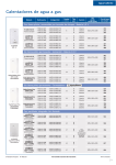
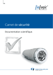
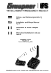
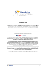
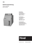
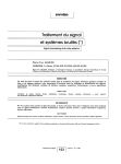
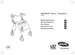
16-653-01
Dit product is deel van het GOOZE-systeem. Voor een beschrijving van het volledige systeem verwijzen wij naar de GOOZE-catalogus of naar www.niko.be.
1. WETTELIJKE WAARSCHUWINGEN
- Lees de volledige handleiding vóór installatie en ingebruikname.
- De installatie dient te worden uitgevoerd door een erkend installateur en met inachtname van de geldende voorschriften.
- Deze handleiding dient aan de gebruiker te worden overhandigd. Zij moet bij het dossier van de elektrische installatie worden gevoegd en dient te worden
overgedragen aan eventuele nieuwe eigenaars. Bijkomende exemplaren zijn verkrijgbaar via de Niko-website of -supportdienst.
- Bij de installatie dient rekening gehouden te worden met (lijst is niet limitatief):
- de geldende wetten, normen en reglementen;
- de stand van de techniek op het ogenblik van de installatie;
- het feit dat een handleiding alleen algemene bepalingen vermeldt en dient gelezen te worden binnen het kader van elke specifieke installatie;
- de regels van goed vakmanschap.
- Bij twijfel kan u de supportdienst van Niko raadplegen of contact opnemen met een erkend controleorganisme.
Support België:
Support Nederland:
tel. + 32 3 760 14 82
tel. + 31 183 64 06 60
website: http://www.niko.be
website: http://www.niko.nl
e-mail: [email protected]
e-mail: [email protected]
In geval van defect kan u uw product terugbezorgen aan een erkende Niko-groothandel samen met een duidelijke omschrijving van uw klacht (manier van
gebruik, vastgestelde afwijking…).
2. BESCHRIJVING
Met het U SEE ONE pakket kan u het beeld van uw bezoeker aan uw GOOZE-buitenpost op uw pc zien.
Terwijl u op uw pc werkt, staat het programma in standby op de achtergrond. Als iemand aanbelt, komt het programma op de voorgrond en verschijnt het
beeld van de bezoeker op het scherm. U kan met uw bezoeker communiceren via een normale telefoon (optioneel aansluitbaar). U kan ook de elektrische
sloten via uw pc bedienen. U kan het beeld van uw bezoeker opslaan tijdens het gesprek of het beeld automatisch opslaan telkens iemand aanbelt. De
weergaveresolutie is instelbaar. Het U SEE ONE pakket bevat de software voor installatie op een pc, een USB-convertor, de UNIVERSAL MODULE (16-65601), de nodige kabels en deze handleiding.
3. INSTALLATIE
Volg de instructies op in de volgorde die staat aangegeven!
3.1. Bekabeling
- Leg een UTP-kabel met RJ45-connectoren aan weerszijden van de splitter of switcher naar de UNIVERSAL MODULE (16-656-01) van het U SEE ONE
pakket.
- Sluit de coaxkabel met BNC-connectoren rechtstreeks aan op de UNIVERSAL MODULE en via het bijgeleverde passtuk (BNC naar cinch) op de videoingang (geel) van de USB-convertor.
3.2. De drivers voor de USB-convertor installeren
Installeer de drivers vóór u de hardware aan de pc koppelt! Plaats de cd die bij de USB-convertor zit in de computer. Voor de details en installatie van de
USB-convertor, zie handleiding van de USB-convertor.
Installatieprocedure
Nadat u de Quick installation Guide van de USB-convertor doorlopen hebt, komt u in het auto-run hoofdscherm. Kies ‘install drivers’. Dubbelklik op ‘next >’.
In het derde scherm moet de cd-rom drive aangevinkt zijn. Klik vervolgens opnieuw op ‘next >’.
Opgelet: Als u met WINDOWS XP werkt, zal u een viertal keer een waarschuwing krijgen dat de software niet compatibel is (zie fig. 2). Dit is een verplichte
waarschuwing omdat de software niet door MICROSOFT geschreven werd. Klik op ‘Continue anyway’. Dit houdt geen risico’s in. Klik uiteindelijk op ‘Finish’.
De drivers zijn nu geïnstalleerd.
Opmerking:
De installatie van de drivers is voldoende om de GOOZE-pc-oplossing te laten functioneren! Als u gebruik wil maken van de andere mogelijkheden die de
USB-convertor biedt, moet u nog meer installeren. Verdere installatie wordt NIET ondersteund door Niko NV.
3.3. De GOOZE-gebruikerssoftware installeren
Plaats de GOOZE-cd-rom in de computer. De installatie start automatisch op (*). Het volgende scherm verschijnt (fig.1). Via ‘Browse Contents’ kan u de verschillende bestanden
van de cd-rom bekijken. Start de installatie op via ‘Install Products’. U kan een rechtsreekse link naar andere Niko-producten of de Niko-website creëren. Klik op ‘contact us’
voor de contactgegevens van Niko. Wenst u de installatie later uit te voeren, dan kan u
via de ‘Exit’-knop de installatieprocedure verlaten!
fig.1: startscherm van de GOOZE-software
1
16-653-01
STAP 1:Onder de eerste stap van ‘Install Products’ wordt nog eens vermeld dat u eerst de drivers voor de USB-convertor moet installeren.
Dit is normaal reeds in punt 3.2. gebeurd.
Opgelet: Als u met WINDOWS XP werkt, zal u een viertal keer een waarschuwing krijgen dat de software
niet compatibel is (zie fig. 2). Dit is een verplichte waarschuwing omdat de software niet door MICROSOFT geschreven werd. Klik op ‘Continue anyway’. Dit houdt geen risico’s in. Klik uiteindelijk op ‘Finish’.
Rechts onderaan het scherm verschijnt: ‘New hardware is installed and ready to use’. De hardware werd
succesvol geïnstalleerd.
fig.2: waarschuwingsscherm bij een pc met WINDOWS XP
STAP 2: de hardware aan de pc koppelen
Gebruik een vrije USB-poort en COM-poort voor de convertor en de RS232-kabel van de UNIVERSAL MODULE. Als de COM-poort (**) niet gelijk is aan
COM 1 (op uw pc), stel dan de juiste poort in (zie ‘4. WERKING EN GEBRUIK’).
Opgelet: Het is mogelijk dat u de hardware 2x moet installeren. Dit hangt af van de gebruikte WINDOWS-versie!
STAP 3: de U SEE ONE SOFTWARE installeren
Lees eerst de overeenkomst en accepteer ze. Klik op ‘next>’ om naar het volgende scherm
te gaan.
Vul in het volgende scherm de naam van de installateur en de naam van het bedrijf van de
installateur in. Klik op ‘next>’. Selecteer dan de map waarin u de bestanden wil opslaan. Klik
op ‘next>’. Klik op ‘install’ en vervolgens op ‘Finish’. De installatie is voltooid!
Als u reeds een deel geïnstalleerd had, kies dan in het
eerste scherm voor ‘repair’
(fig.3). Klik vervolgens op
‘Finish’. De installatie is voltooid!
fig.3: selecteer ‘repair’ om verder te gaan met de installatie
STAP 4: DIRECTX9 installeren
Lees eerst de overeenkomst en accepteer ze. Enkel zo kan het systeem correct geïnstalleerd worden.
Opgelet! De pc zal nu automatisch afsluiten en opnieuw opstarten. Is dit niet het geval, doe dit dan zelf. De U SEE ONE pc-oplossing is nu klaar voor
gebruik. Voor meer informatie over het gebruik van dit programma, zie ‘4. WERKING EN GEBRUIK’.
(*) Als de installatie niet automatisch opstart, open de cd-rom dan via ‘My Computer’!
(**) Als u geen (vrije) RS232-poort op uw pc heeft, kan u ook een tweede vrije USB-poort met een USB/RS232 adapter/omzetter gebruiken.
16-670
16-672
16-676-01
De bijgeleverde voetjes (4) kan u onderaan de UNIVERSAL MODULE (16-656-01) kleven.
2
PC
16-653-01
4. WERKING EN GEBRUIK
- Als u de computer opstart, kan u het U See One programma openen. Het systeem vraagt u eerst de gebruikte COM-poort in te stellen (fig.4). Druk vervolgens op ‘next’ om verder te gaan.
Is deze poort niet correct ingesteld, dan kan het programma niet correct functioneren. Er kan ook een foutmelding optreden waardoor de programmering
niet kan worden afgerond.
Stel vervolgens een adres in:
- 1e UNIVERSAL MODULE in de installatie: adres 00
- 2e UNIVERSAL MODULE in de installatie: adres 01
-…
Klik daarna op ‘link’ en vervolgens op de programmeertoets van de te linken UNIVERSAL MODULE (16-656-01). Als alles correct werd uitgevoerd, verschijnt
volgende bevestiging:
Opmerking:
Voor een uitvoerige beschrijving van de programmering van het videosignaal van een buitenpost op de UNIVERSAL MODULE van de U SEE ONE pc-oplossing, zie de handleiding van de SMART ONE (16-651).
3
16-653-01
U kan het programma op de achtergrond laten draaien door het te minimaliseren. Klik hiervoor op ‘Hide’. Als het programma op de achtergrond werkt, kan
u het terug activeren door op het kleine GOOZE-logo in de Windows-werkbalk te dubbelklikken.
fig.4: startscherm van het U See One programma
- Als iemand aanbelt, verschijnt het programma op de voorgrond en kan u het beeld van uw bezoeker zien (AUTOMATIC POP-UP, fig.7).
- Zolang het beeld actief is, kan u de elektrische sloten activeren. Klik op ‘Entry 1 Lock 1’ of ‘Entry 1 Lock 2’ om slot 1 resp. slot 2 aan de betreffende
buitenpost te openen. De openingsduur van de sloten is instelbaar.
- Klik op ‘camera>>’ om het beeld van de camera(‘s) op te roepen. Als er meerdere camera’s op het systeem aangesloten zijn, kan u door meermaals te
klikken het beeld van de verschillende camera’s één voor één oproepen. Als de beelden van alle camera’s doorlopen werden, krijgt u een zwart scherm. Alle
camera’s staan dan uit en u kan geen sloten meer bedienen.
- Klik op <More…> voor extra gebruiksfuncties. U kan hier ook de instellingen wijzigen (fig.5).
fig.5: scherm met extra gebruiksfuncties en mogelijke instellingen
4
16-653-01
- Klik op ‘Snapshot’ om een foto van het actieve videobeeld op te slaan. Onder de knop verschijnt een preview van het (manueel) genomen snapshot
(fig.6)!
Let op: vóór u de eerste keer een snapshot neemt, moet u een pad vastleggen naar de map waar u de snapshots wil opslaan (zie ‘5. INSTELLINGEN’)!
(Default = C:\photos)
fig.6: scherm met snapshot
- Klik op ‘System settings’ om naar de mogelijke instellingen te gaan.
- Klik op ‘Close’ om de werkbalk met de extra functionaliteiten te sluiten.
Opmerking:
Wil u ook met uw bezoeker praten, dan kan u een telefoon op de RJ12-connector van de universele module aansluiten!
LET OP: in dit geval moet u een analoge binnenlijn van de telefooncentrale aansluiten op de splitterprint (zie
handleiding splitter 16-670/16-72 en switcher 16-676-01)!
5. INSTELLINGEN (fig.7)
Klik op ‘System settings’ om naar de mogelijke instellingen te gaan.
Klik op ‘OK’ rechts bovenaan om de instellingen te bevestigen of te verlaten.
5.1. De openingstijd van de sloten
U kan de openingstijd instellen in stappen van 0,5s. met een minimumtijd van 0,5s. en een maximumtijd van 100s (fig.7). De ingestelde openingstijden voor
slot 1 en slot 2 gelden voor alle gekoppelde buitenposten.
fig.7: scherm met de mogelijke instellingen
5
16-653-01
5.2. Automatic POP-UP
Als u AUTOMATIC POP-UP aanvinkt, komt het GOOZE-scherm automatisch op de voorgrond van uw scherm als er aangebeld wordt of als een externe
camera geactiveerd wordt.
5.3. Automatische snapshot
Als u ‘AUTOMATIC SNAPSHOT ON POP-UP’ aanvinkt (fig.7), verschijnen de mogelijke instellingen:
• het aantal seconden dat na het indrukken van de beldrukknop of het activeren van de externe camera gewacht wordt om een snapshot te nemen.
• de map waarnaar de snapshots weggeschreven worden (geldt ook voor manueel genomen snapshots).
• onder ‘Select Snapshot Resolution’ kan u de weergaveresolutie instellen
5.4. ‘Video Capture Card’ / ‘Video settings’
‘Video settings’ – ‘video setting’ (fig.8):
Hier kan u kiezen om uw beeld horizontaal te spiegelen. Verder kan u hier het videoformaat en de video-input instellen.
fig.8: video settings
‘Video settings’ – ‘Video Proc Amp’ (fig.9):
Hier kan u de helderheid, contrast… van het beeld instellen. Klik op ‘default’ om terug te keren naar de standaardinstellingen.
fig.9: mogelijke instellingen van de Video Proc Amp
6
16-653-01
5.5. COM-poort instellen (fig.7)
Als u op de verkeerde COM-poort aan het werken bent, reageert het systeem niet op de commando’s die u doorstuurt. Let er dus op dat de COM-poort die
u in de software instelt (standaard COM 1) overeenkomt met de COM-poort waarop de U See One aangesloten is.
5.6. LINK ADDRESS (fig.7)
Indien 2x hetzelfde adres ingesteld is in één installatie, kan hier alsnog het adres gewijzigd worden. Eén UNIVERSAL MODULE moet dan opnieuw gelinkt
worden.
6. TECHNISCHE GEGEVENS
Afmetingen UNIVERSAL MODULE: ................. L 114 x B 76 x H 32mm
Minimum pc-configuratie: .............................. Windows 98SE, 2000, ME of XP
Pentium III 800MHz, 64Mb RAM,
één vrije USB-poort en één vrije RS-232-poort
Bediening elektrische sloten: .......................... 2 per SMART ONE
Weergaveresolutie: .......................................... max. 640 x 480
7. GARANTIEBEPALINGEN
- Garantietermijn: twee jaar vanaf leveringsdatum. Als leveringsdatum geldt de factuurdatum van aankoop van het goed door de consument. Indien geen
factuur voorhanden is, geldt de productiedatum.
- De consument is verplicht Niko schriftelijk over het gebrek aan overeenstemming te informeren, uiterlijk binnen de twee maanden na vaststelling.
- In geval van een gebrek aan overeenstemming van het goed heeft de consument recht op een kosteloze herstelling of vervanging, wat door Niko bepaald
wordt.
- Niko is niet verantwoordelijk voor een gebrek of schade als gevolg van een foutieve installatie, oneigenlijk of onachtzaam gebruik of verkeerde bediening
of transformatie van het goed.
- De dwingende bepalingen van de nationale wetgevingen betreffende de verkoop van consumptiegoederen en de bescherming van de consumenten van
de landen waarin Niko rechtstreeks of via zuster/dochtervennootschappen, filialen, distributeurs, agenten of vaste vertegenwoordigers verkoopt, hebben
voorrang op bovenstaande bepalingen.
7
16-653-01
8
16-653-01
Ce produit fait partie intégrante du système GOOZE. Pour une description du système complet, nous vous renvoyons au catalogue GOOZE ou au site Internet
www.niko.be.
1. PRESCRIPTIONS LEGALES
- Lisez entièrement le mode d’emploi avant toute installation et mise en service.
- L’installation doit être effectuée par un installateur agréé et dans le respect des prescriptions en vigueur.
- Ce mode d’emploi doit être remis à l’utilisateur. Il doit être joint au dossier de l’installation électrique et être remis à d’éventuels autres propriétaires. Des
exemplaires supplémentaires peuvent être obtenus sur le site web ou auprès du service ‘support Niko’.
- Il y a lieu de tenir compte des points suivants avant l’installation (liste non limitative):
- les lois, normes et réglementations en vigueur;
- l’état de la technique au moment de l’installation;
- ce mode d’emploi qui doit être lu dans le cadre de toute installation spécifique;
- les règles de l’art.
- En cas de doute, vous pouvez appeler le service ‘support Niko’ ou vous adresser à un organisme de contrôle reconnu.
Support Belgique:
Support France:
+ 32 3 760 14 82
+ 33 4 78 66 66 20
site web: http://www.niko.be
site web: http://www.niko.fr
e-mail: [email protected]
e-mail: [email protected]
En cas de défaut de votre appareil, vous pouvez le retourner à un grossiste Niko agréé, accompagné d’une description détaillée de votre plainte (manière
d’utilisation, divergence constatée…).
2. DESCRIPTION
Grâce à l’ensemble U SEE ONE, vous pouvez voir sur votre PC l’image du visiteur qui se présente devant votre poste extérieur GOOZE.
Pendant que vous travaillez sur votre PC, le programme est placé en stand-by en arrière-plan. Lorsque quelqu’un sonne, le programme vient à l’avant-plan et
l’image du visiteur s’affiche à l’écran. Vous pouvez communiquer avec le visiteur au moyen d’un téléphone normal (connexion en option). Vous pouvez aussi
commander les gâches électriques grâce à votre PC. Vous pouvez enregistrer l’image du visiteur pendant la conversation ou enregistrer automatiquement
l’image chaque fois que quelqu’un sonne. La résolution de reproduction est réglable. L’ensemble U SEE ONE comprend le logiciel pour l’installation sur un
PC, un convertisseur USB, le MODULE UNIVERSEL (16-656-01), les câbles nécessaires et ce mode d’emploi.
3. INSTALLATION
Suivez les instructions dans l’ordre où elles sont données!
3.1. Câblage
- A l’aide d’un câble UTP avec connecteurs RJ45 de part et d’autre, reliez le répartiteur ou le sélecteur au MODULE UNIVERSEL (16-656-01) de l’ensemble
U SEE ONE.
- Raccordez le câble coaxial muni de connecteurs BNC directement au MODULE UNIVERSEL et, via l’adaptateur fourni (BNC vers cinch), à l’entrée vidéo
(jaune) du convertisseur USB.
3.2. Installation des pilotes pour le convertisseur USB
Installez les pilotes avant de raccorder le matériel au PC! Insérez le CD fourni avec le convertisseur USB dans le lecteur de CD-ROM de l’ordinateur. Pour
plus de détails et pour installer le convertisseur USB, reportez-vous au mode d’emploi du convertisseur USB.
Procédure d’installation
Après avoir parcouru le guide d’installation rapide du convertisseur USB, vous parvenez à l’écran d’auto-exécution. Choisissez ‘install drivers’ (installer
les pilotes). Double-cliquez sur ‘next >’ (suivant >). Dans le troisième écran, il faut cocher le lecteur de CD-ROM. Cliquez ensuite à nouveau sur ‘next >’
(suivant >).
Attention: Si vous travaillez sous WINDOWS XP, vous recevrez quatre fois un avertissement comme quoi le logiciel n’est pas compatible (voir fig. 2). C’est
un avertissement obligatoire qui s’affiche parce que le logiciel n’est pas édité par MICROSOFT. Cliquez sur ‘Continue anyway’ (continuer malgré tout). Cela
n’implique aucun risque. Cliquez finalement sur ‘Finish’ (terminer). Les pilotes sont à présent installés.
Remarque:
L’installation des pilotes est suffisante pour faire fonctionner la solution PC GOOZE! Si vous voulez utiliser d’autres fonctionnalités du convertisseur USB,
vous devez continuer l’installation. Cette installation supplémentaire n’est PAS cautionnée par Niko SA.
3.3. Installation du logiciel de l’utilisateur GOOZE
Insérez le CD-ROM GOOZE dans le lecteur de CD-ROM de l’ordinateur. L’installation
commence automatiquement (*). L’écran suivant s’affiche (fig. 1). En utilisant ‘Browse
Contents’ (parcourir le contenu), vous pouvez voir les différents fichiers qui figurent sur
le CD-ROM. Commencez l’installation grâce à ‘Install Products’ (installer les produits).
Il vous est également possible de créer un lien direct vers d’autres produits Niko ou le
site web Niko. Cliquez sur ‘contact us’ (nous contacter) pour trouver les coordonnées
de Niko. Si vous souhaitez exécuter l’installation ultérieurement, vous pouvez quitter la
procédure d’installation via le bouton ‘Exit’ (quitter)!
fig.1: écran de démarrage du logiciel GOOZE
9
16-653-01
ETAPE 1: installer les pilotes pour le convertisseur USB
Cette opération a normalement déjà été effectuée au point 3.2.
Attention: Si vous travaillez sous WINDOWS XP, vous recevrez quatre fois un avertissement comme
quoi le logiciel n’est pas compatible (voir fig. 2). C’est un avertissement obligatoire qui s’affiche parce que
le logiciel n’est pas édité par MICROSOFT. Cliquez sur ‘Continue anyway’ (continuer malgré tout). Cela
n’implique aucun risque. Cliquez finalement sur ‘Finish’ (terminer). Dans le coin inférieur droit de l’écran
apparaît l’indication: ‘New hardware is installed and ready to use’ (Nouveau matériel installé et prêt à être
utilisé). Le matériel a été installé avec succès.
fig.2: écran d’avertissement pour un PC équipé de WINDOWS XP
ETAPE 2: raccorder le matériel au PC
Utilisez un port USB et un port COM libres pour le convertisseur et le câble RS232 du MODULE UNIVERSEL. Si votre port COM (**) n’est pas le COM 1
(sur votre PC), réglez le port adéquat (voir ‘5. REGLAGES’).
Attention: Il est possible que vous deviez installer 2 fois le matériel. Cela dépend de la version de WINDOWS que vous utilisez!
ETAPE 3: installer le LOGICIEL U SEE ONE
Lisez d’abord le contrat et acceptez-le. Cliquez sur ‘next>’ (suivant>) pour passer à l’écran suivant.
Remplissez sur l’écran suivant le nom de l’installateur et le nom de sa société. Cliquez sur
‘next>’. Choisissez ensuite le dossier dans lequel vous voulez enregistrer les fichiers. Cliquez
sur ‘next>’. Cliquez sur ‘install’ (installer) et ensuite sur ‘Finish’ (terminer). L’installation est
terminée!
Si vous aviez déjà installé une
partie du logiciel, choisissez
sur le premier écran ‘repair’
(réparer) (fig.3). Cliquez ensuite sur ‘Finish’ (terminer).
L’installation est terminée!
fig.3: choisissez ‘repair’ (réparer) pour continuer l’installation
ETAPE 4: installer DIRECTX9
Lisez d’abord le contrat et acceptez-le. C’est la seule manière pour que le système soit installé correctement.
Attention! Le PC va maintenant se fermer automatiquement et redémarrer. Si ce n’est pas le cas, faites-le manuellement. La solution PC U See One peut
maintenant être utilisée. Pour plus d’informations sur l’utilisation de ce programme, reportez-vous à 4. FONCTIONNEMENT ET UTILISATION.
(*) Si l’installation ne commence pas automatiquement, ouvrez le CD-ROM via l’icône ‘My Computer’ (poste de travail)!
(**) Si votre PC ne possède pas de port RS232 (libre), vous pouvez également utiliser un deuxième port USB libre équipé d’un adaptateur/convertisseur
USB/RS232.
16-670
16-672
16-676-01
Les pieds fournis (4) peuvent être collés sous le MODULE UNIVERSEL (16-656-01).
10
PC
16-653-01
4. FONCTIONNEMENT ET UTILISATION
- Si vous faites démarrer l’ordinateur, vous pouvez ouvrir le programme U See One. Le système vous demande d’indiquer le port COM utilisé (fig.4).
Appuyez ensuite sur ‘next’ pour continuer.
- Si le port utilisé n’est pas indiqué correctement, le programme ne pourra pas fonctionner correctement. Il est également possible qu’un message d’erreur
apparaît de sorte que la programmation ne peut pas être terminée.
Attribuez ensuite une adresse :
- 1er MODULE UNIVERSEL dans l’installation: adresse 00
- 2e MODULE UNIVERSEL dans l’installation: adresse 01
-…
Cliquez alors sur ‘link’ et enfoncez ensuite la touche de programmation du MODULE UNIVERSEL à lier (16-656-01). Si la procédure est effectuée correctement, la confirmation suivante apparaîtra.
Remarque:
Pour une description détaillée de la programmation du signal vidéo du poste extérieur sur le MODULE UNIVERSEL de la solution pc U SEE ONE, consultez
le mode d’emploi du SMART ONE (16-651)
11
16-653-01
Vous pouvez laisser tourner le programme en arrière-plan en le minimalisant. Pour ce faire, cliquez sur ‘Hide’ (cacher). Lorsque le programme tourne en
arrière-plan, vous pouvez à nouveau l’activer en double-cliquant sur le petit logo GOOZE dans la barre des tâches Windows.
fig.4: écran de démarrage du programme U See One
- Lorsque quelqu’un sonne, le programme vient à l’avant-plan et l’image du visiteur s’affiche à l’écran (AUTOMATIC POP-UP, fig.7).
- Tant que l’image est active, vous pouvez actionner les gâches électriques. Cliquez sur ‘Entry 1 Lock 1’ (entrée 1, gâche 1) ou ‘Entry 1 Lock 2’ (entrée 1,
gâche 2) pour ouvrir respectivement la gâche 1 ou la gâche 2 du poste extérieur concerné. La durée d’ouverture des gâches est réglable.
- Cliquez sur ‘camera>>’ (caméra>>) pour appeler l’image de la (des) caméra(s). Si plusieurs caméras sont raccordées au système, vous pouvez appeler
l’image des différentes caméras par clics successifs sur ce même bouton. Lorsque vous aurez parcouru les images de toutes les caméras, vous verrez un
écran noir. Toutes les caméras sont éteintes et vous ne pouvez plus actionner de gâches.
- Cliquez sur <More…> (<plus...>) pour des fonctions d’utilisation supplémentaires. Vous pouvez aussi modifier les réglages (fig. 5).
fig.5: écran avec fonctions d’utilisation supplémentaires et réglages possibles
12
16-653-01
- Cliquez sur ‘Snapshot’ (instantané) pour enregistrer une photo de l’image vidéo active. Une prévisualisation de l’instantané pris (manuellement) apparaît
sous le bouton (fig. 6)!
Attention: avant de prendre pour la première fois un instantané, vous devez préciser le chemin vers le dossier où vous voulez enregistrer les instantanés
(voir 5. REGLAGES)! (Par defaut = C:\photos)
fig.6: écran avec instantané
- Cliquez sur ‘System settings’ (réglages du système) pour accéder aux réglages possibles.
- Cliquez sur ‘Close’ (fermer) pour fermer la barre des tâches qui propose les fonctionnalités supplémentaires.
Remarque:
Si vous voulez également communiquer avec votre visiteur, vous devez alors raccorder un téléphone au connecteur
RJ12 du module universel!
ATTENTION: dans ce cas, vous devez raccorder une ligne intérieure analogique du central téléphonique au circuit
imprimé (voir le mode d’emploi du répartiteur 16-670/16-672 et du sélecteur 16-676-01)!
5. REGLAGES (fig.7)
Cliquez sur ‘System settings’ (réglages du système) pour accéder aux réglages possibles.
Cliquez sur ‘OK’ dans le coin supérieur droit pour confirmer le mode de réglage ou le quitter.
5.1. La durée d’ouverture des gâches
Vous pouvez régler la durée d’ouverture par incréments de 0,5s., avec une valeur min. de 0,5s. et une valeur max. de 100s. (fig.7). Les durées d’ouvertures
spécifiées pour la gâche 1 et pour la gâche 2 sont d’application pour tous les postes extérieurs raccordés.
fig.7: écran avec les réglages possibles
13
16-653-01
5.2. Automatic POP-UP
Si vous cochez AUTOMATIC POP-UP (apparition automatique), l’écran GOOZE apparaît automatiquement à l’avant-plan de votre écran lorsque quelqu’un
sonne ou qu’une caméra externe est activée.
5.3. Instantané automatique
Si vous cochez ‘AUTOMATIC SNAPSHOT ON POP-UP’ (instantané) (fig.7), les réglages possibles s’affichent:
• le nombre de secondes d’attente avant de prendre un instantané, calculé à partir du moment où le bouton de sonnerie a été enfoncé ou du moment où la
caméra externe a été activée.
• le dossier dans lequel les instantanés sont enregistrés (également valable pour les instantanés pris manuellement).
• sous ‘Select Snapshot Resolution’ (choisir la résolution des instantanés), vous pouvez régler la résolution de reproduction.
5.4. ‘Video Capture Card’ / ‘Video settings’
‘Video settings’ – ‘video setting’ (réglages vidéo) (fig.8):
Vous pouvez choisir ici d’afficher l’image au format paysage. Vous pouvez aussi régler le format vidéo et l’entrée vidéo.
fig.8: réglages possibles lors de la prise d’un instantané
‘Video settings’ – ‘Video Proc Amp’ (fig.9):
Vous pouvez régler ici la luminosité, le contraste... de l’image. Cliquez sur ‘default’ (défaut) pour revenir aux réglages standard.
fig.9: réglages possibles du Video Proc Amp
14
16-653-01
5.5. Réglage du port COM (fig.7)
Si vous travaillez sur le mauvais port COM, le système ne réagit pas aux commandes que vous envoyez. Veillez donc à ce que le port COM que vous avez
réglé dans le logiciel (en standard, COM 1) corresponde au port COM sur lequel le U See One est raccordé.
5.6. LINK ADDRESS (fig.7)
S’il y a réglé 2 fois la même adresse dans une seule installation, l’adresse peut ici encore être modifiée. Le cas échéant, un MODULE UNIVERSEL doit de
nouveau être lié.
6. CARACTERISTIQUES TECHNIQUES
Dimensions du MODULE UNIVERSEL: ........... L 114 x l 76 x H 32mm
Configuration PC minimale: ............................ Windows 98SE, 2000, ME ou XP
Pentium III 800MHz, 64Mb RAM,
un port USB libre et un port RS-232 libre
Commande gâches électriques: ...................... 2 par SMART ONE
Résolution de reproduction: ............................ max. 640 x 480
7. CONDITIONS DE GARANTIE
- Délai de garantie: 2 ans à partir de la date de livraison. La date de la facture d’achat par le consommateur fait office de date de livraison. Sans facture
disponible, la date de fabrication est seule valable.
- Le consommateur est tenu de prévenir Niko par écrit de tout manquement à la concordance des produits dans un délai max. de 2 mois après constatation.
- Au cas ou pareil manquement serait constaté, le consommateur a droit à une réparation gratuite ou à un remplacement gratuit selon l’avis de Niko.
- Niko ne peut être tenu pour responsable pour un défaut ou des dégâts suite à une installation fautive, à une utilisation contraire ou inadaptée ou à une
transformation du produit.
- Les dispositions contraignantes des législations nationales ayant trait à la vente de biens de consommation et la protection des consommateurs des
différents pays où Niko procède à la vente directe ou par entreprises interposées, filiales, distributeurs, agents ou représentants fixes, prévalent sur les
dispositions susmentionnées.
15
16-653-01
16
16-653-01
Dieses Produkt ist ein Teil des GOOZE-Systems. Die Beschreibung des gesamten Systems finden Sie im GOOZE-Katalog und in der Bedienungsanleitung
oder auf unserer Web-Seite www.niko.be.
1. GESETZLICHE BESTIMMUNGEN
- Lesen Sie vor der Montage und Inbetriebnahme die vollständige Gebrauchsanleitung.
- Die Installation darf ausschließlich von einem Fachmann des Elektrohandwerks unter Berücksichtigung der geltenden Vorschriften vorgenommen werden.
- Übergeben Sie dem Benutzer diese Gebrauchsanleitung. Sie ist den Unterlagen der elektrischen Anlage beizufügen und muss auch eventuellen neuen
Besitzern übergeben werden. Zusätzliche Exemplare erhalten Sie über unsere Website oder unseren Servicedienst.
- Bei der Installation müssen Sie u.a. Folgendes berücksichtigen:
- die geltenden Gesetze, Normen und Vorschriften;
- den Stand der Technik zum Zeitpunkt der Installation;
- diese Gebrauchsanleitung die im Zusammenhang mit jeder spezifischen Anlage gesehen werden muss;
- die Regeln fachmännischen Könnens.
- Sollten Sie Fragen haben, können Sie sich an die Niko-Hotline oder an eine anerkannte Kontrollstelle wenden:
Web-site: http://www.niko.be; E-Mail: [email protected];
Hotline Belgien: +32 3 760 14 82
Hotline Moeller Deutschland:
Berlin: +49 30 701902-46
Hamburg: +49 40 75019-281
Düsseldorf: +49 2131 317-37
Frankfurt a.M.: +49 69 50089-263
Stuttgart: +49 711 68789-51
München: +49 89 460 95-218
Mail: [email protected]
Österreich: Moeller Gebäudeautomation UG Schrems 0043-2853-702-0
Hotline Slowakei: +421 263 825 155 – E-mail: [email protected]
Im Falle eines Defektes an Ihrem Niko-Produkt, können Sie dieses mit einer genauen Fehlerbeschreibung (Anwendungsproblem, festgestellter Fehler, usw.)
an Ihren Moeller- oder Niko-EGH zurückbringen.
2. BESCHREIBUNG
Mit dem U SEE ONE–Packet kann man das Bild eines Besuchers, der vor der GOOZE Außentürsprechstelle steht auf dem PC darstellen. Während man z.B.
am PC arbeitet steht, dieses Programm im Hintergrund auf 'stand by'. Sobald nun jemand an der Tür klingelt, wird dieses Programm aktiviert und das Bild
des Besuchers erscheint auf dem Bildschirm. Man kann nun mit dem Besucher über ein normales Telefon, das optional anschließbar ist, kommunizieren.
Auch die elektrischen Türschlösser können über den PC bedient werden. Ein Bild des Besuchers kann während des Gesprächs oder automatisch, sobald
jemand klingelt, im PC abgelegt werden. Die Bildauflösung ist dabei einstellbar. Das U SEE ONE–Packet enthält die Installationssoftware für den PC, einen
USB-Konverter, das UNIVERSAL-MODUL (16-656-91), die nötigen Verbindungskabel sowie diese Bedienungsanleitung.
3. MONTAGE
Folgen Sie bitte den angegebenen Schritten in genau der Reihenfolge!
3.1. Verdrahtung
- Das UTP-'twisted pair'-Kabel mit den RJ45–Steckern an jeder Seite, aus dem U SEE ONE–Packet, wird vom 'Videosplitter' oder 'Videoswitcher' zum
UNIVERSAL-MODUL (16-656-91) gelegt.
- Nun wird das Koaxkabel mit den BNC-Steckern direkt am UNIVERSAL-MODUL angeschlossen und mit dem mitgelieferten Adapter (BNC auf Cinch) an
den Videoeingang (gelb) des USB-Konverters.
3.2. Installation der Treiber für den USB-Konverter
Die Treiber müssen installiert werden bevor die Hardware angeschlossen wird! Dazu wird die CD, die dem USB-Konverter beiliegt, in das CD-Laufwerk des
PC's eingelegt. Weitere Details zum USB-Konverter und dessen Installation finden Sie in dessen Bedienungsanleitung.
Installationsprozedur
Nachdem der Quick installation guide des USB-Konverters durchgegangen wurde, kommt man in das Auto-run-Hauptfenster. Dort wählt man 'install drivers'
und doppelklickt man auf 'next >'. Im dritten Fenster muss dann das CD-Rom-Laufwerk angekreuzt und danach wieder mit 'next >' bestätigt werden.
Achtung: Wird mit WINDOWS XP gearbeitet, so erhält man viermal einen Warnhinweis, dass die Software nicht kompatibel ist (siehe Bild 2). Diese
Warnmeldung erfolgt deshalb, da die Software nicht von MICROSOFT geschrieben wurde. Man klickt nun auf 'Continue anyway' ohne hierdurch ein Risiko
einzugehen. Zum Schluss wird dann auf 'Finish' geklickt. Die Treiber sind nun installiert.
Hinweis: Die Installation der Treiber ist für die Funktion der GOOZE-PC-Lösung ausreichend. Soll der USB-Konverter noch für andere mögliche Funktionen eingesetzt werden, so sind noch weitere Installationen notwendig. Diese weiteren
Installationen werden NICHT durch Niko unterstützt.
3.3. Installation der GOOZE-Anwendersoftware
Nach Einlegen der GOOZE–CD-ROM in das CD-Laufwerk startet die Installation automatisch (*). Das nächste Fenster erscheint (Bild 1). Über 'Browse Contents' können die verschiedenen Dateien der CD-ROM aufgerufen werden. Die Installation wird über 'Install
Products' gestartet. Man kann auch einen direkten 'link' zu anderen Niko-Produkten oder
der Niko-Webseite anlegen. Wird 'Contact us' angeklickt, so werden die Adressdaten von
Niko angezeigt. Soll die Installation zu einem späteren Zeitpunkt ausgeführt werden, so
kann man die Installationsprozedur über die 'Exit' -Schaltfläche verlassen.
Bild 1: Startfenster der GOOZE-Software
17
16-653-01
SCHRITT 1: Bei dem ersten Schritt unter 'Install Products' wird nochmals darauf hingewiesen, dass erst die Treiber für den USB-Konverter installiert
werden müssen. Dies ist normalerweise bereits bei '3.2. Installation der Treiber für den USB-Konverter' erfolgt.
Achtung: Wird mit WINDOWS XP gearbeitet, so erhält man viermal einen Warnhinweis, dass die Software nicht kompatibel ist (siehe Bild 2). Diese Warnmeldung erfolgt deshalb, da die Software nicht von MICROSOFT geschrieben wurde. Man klickt nun auf 'Continue anyway' ohne hierdurch ein Risiko einzugehen.
Zum Schluss wird dann auf 'Finish' geklickt. Rechts unten im Fenster erscheint nun: 'New hardware is
installed and ready to use' (Die Hardware wurde erfolgreich installiert).
Bild 2: Warnungsfenster bei einem PC mit WINDOWS XP
SCHRITT 2: Die Hardware mit dem PC verbinden
Man verwendet hierzu einen freien USB-Port und den COM-Port für den Konverter und das RS232–Kabel des UNIVERSAL-MODULS. Wenn der COM-Port
(**) nicht gleich COM 1 ist auf Ihrem PC, dann muss der richtige Port eingestellt werden (siehe '4. FUNKTIONSWEISE UND ANWENDUNG').
Achtung: Es kann sein, dass die Hardware 2x installiert werden muss. Dies hängt von der verwendeten WINDOWS-Version ab.
SCHRITT 3: Installation der U SEE ONE–Software
Zuerst wird die Vereinbarung durchgelesen und ggf. akzeptiert. Mit 'next >' gelangt man
zum nächsten Fenster. Im nächsten Fenster werden dann der Name des Installateurs und der
Name des Installationsbetriebes eingetragen. Nach Anklicken von 'next >' wird nun der File
ausgewählt, in dem die Daten abgelegt werden sollen. Nun klickt man auf 'next >', danach auf
'install' und dann auf 'finish'. Die Installation wurde durchgeführt!
Falls man bereits einen Teil
installiert hatte, so wählt man
im ersten Fenster 'repair' (s.
Bild 3). Danach klickt man
dann auf 'finish'. Die Installation wurde durchgeführt!
Bild 3: Man wählt 'repair' um mit der Installation fortzufahren
SCHRITT 4: Installation der DIRECTX 9–Software
Zuerst wird die Vereinbarung durchgelesen und ggf. akzeptiert. Nur so kann das System korrekt installiert werden.
Achtung! Der PC wird nun automatisch runterfahren und neu starten. Ist dies nicht der Fall, so sollten Sie es selbst tun. Die U SEE ONE–PC-Lösung ist
nun einsatzbereit. Für weitere Informationen zum Einsatz dieses Programms, siehe '4. FUNKTIONSWEISE UND ANWENDUNG'.
(*) Sollte die Installation nicht automatisch starten, so öffnen Sie die CD-ROM über 'My Computer'!
(**) Falls kein (freier) RS232–Port auf dem PC vorhanden ist, so kann auch ein zweiter, freier USB-Port mit einem USB/RS232–Adapter verwendet werden.
16-670
16-672
16-676-01
PC
Die mitgelieferten Gerätefüße (4) können auf dem Gehäuseboden des UNIVERSAL MODULS (16-656-01) aufgeklebt werden.
18
16-653-01
4. FUNKTIONSWEISE UND ANWENDUNG
- Wird der PC hochgefahren so kann das U SEE ONE–Programm geöffnet werden. Das System fragt zuerst nach der Einstellung des verwendeten COMPorts (s. Bild 4). Danach klickt man auf 'next >' um weiterzumachen.
Ist dieser Port nicht richtig eingestellt, so kann das Programm nicht korrekt arbeiten. Es kann auch eine Fehlermeldung angezeigt werden wodurch die
Programmierung nicht zu Ende geführt werden kann. Danach wird eine Adresse eingestellt:
- 1.UNIVERSAL MODUL in der Anlage: Adresse 00
- 2.UNIVERSAL MODUL in der Anlage: Adresse 01
- …..
Danach klickt man auf 'link' und dann auf den Programmiertaster von dem zu verbindenden UNIVERSAL MODUL (16-656-01). Wenn alles richtig ausgeführt
wurde, erscheint folgende Bestätigung:
Hinweis:
Eine ausführliche Beschreibung der Programmierung des Videosignals von einer Außentürsprechstelle auf das UNIVERSAL MODUL der U SEE ONE–PCLösung, findet man in der Bedienungsanleitung des SMART ONE (16-651).
19
16-653-01
Man kann das Programm im Hintergrund laufen lassen indem man es minimiert. Dazu klickt man auf 'hide'. Wenn das Programm im Hintergrund läuft, so
kann es wieder durch doppelklicken des kleinen GOOZE-Logos in der WINDOWS–Taskliste aktiviert werden.
Bild 4: Startfenster des U SEE ONE–Programms
- Wenn jemand klingelt, so tritt das Programm in den Vordergrund und erscheint das Bild des Besuchers auf dem Bildschirm (AUTOMATIC POP-UP, Bild 7).
- Solange das Bild aktiv ist können auch die elektrischen Türschlösser bedient werden. Um Schloss 1 bzw. Schloss 2 der entsprechenden Außentürsprechstelle zu bedienen wird 'Entry 1 Lock 1' oder 'Entry 1 Lock 2' angeklickt. Die Öffnungsdauer der Schlösser ist einstellbar.
- Um das Bild der Kamera(s) aufzurufen wird auf 'camera >>' geklickt. Sind mehrere Kameras am System angeschlossen, so können durch mehrmaliges
anklicken die Bilder der einzelnen Kameras nacheinander aufgerufen werden. Nachdem die Bilder aller Kameras aufgerufen wurden, erscheint ein schwarzes Fenster. Alle Kameras sind dann deaktiviert und es kann kein Schloss mehr bedient werden.
- Wird auf <More…> geklickt, so können weiter Anwenderfunktionen aufgerufen werden. Man kann hier auch die Einstellungen ändern (s. Bild 5).
Bild 5: Fenster mit weiteren Anwenderfunktionen und möglichen Einstellungen
20
16-653-01
- durch Anklicken von 'Snapshot' wird ein Foto des aktiven Videobildes abgespeichert. Unter der Schaltfläche erscheint ein Vorschaubild des (manuell)
aufgenommenen 'Snapshots' (s. Bild 6)!
Achtung: Bevor man das erste Mal einen 'Snapshot' aufnimmt, muss festgelegt werden in welcher Datei der 'Snapshot' abgelegt werden soll (siehe '5.
EINSTELLUNGEN')! (Fabriksvoreinstellung / Default = C:\photos)
Bild 6: Fenster mit Snapshot
- durch Anklicken von 'System settings' können die verschiedenen Einstellungen vorgenommen werden.
- Durch Anklicken von 'Close' wird die Taskliste mit den weiteren Anwenderfunktionen geschlossen.
Anmerkung:
Soll auch mit dem Besucher gesprochen werden können, dann kann ein normales Telefon an die RJ12-Buchse am
UNIVERSAL MODUL angeschlossen werden.
ACHTUNG: In diesem Fall muss ein analoger Nebenstellenanschluss von der Nebenstellenanlage auf der 'Splitter'-Leiterplatte angeschlossen werden (siehe Bedienungsanleitung des Splitters 16-670/16-72 und des Switchers
16-676-01)!
5. EINSTELLUNGEN (Bild 7)
- durch Anklicken von 'System settings' können die verschiedenen Einstellungen vorgenommen werden.
- Durch Anklicken von 'OK' oben rechts werden die Einstellungen bestätigt oder verlassen.
5.1. Einstellen der Öffnungszeit der elektrischen Schlösser
Die Öffnungszeit kann in Schritten von 0,5s eingestellt werden mit der kleinsten Zeit von 0,5s und einer maximalen Zeit von 100s. Die eingestellten Öffnungszeiten von Schloss 1 und Schloss 2 gelten für alle angeschlossenen Außentürsprechstellen.
Bild 7: Fenster mit den möglichen Einstellungen
21
16-653-01
5.2. Automatisches POP-UP
Wird 'AUTOMATIC POP-UP' angekreuzt, dann tritt das GOOZE-Fenster automatisch in den Vordergrund auf dem Bildschirm sobald geklingelt wird oder
wenn eine externe Kamera aktiviert wird.
5.3. Automatische Snapshots
Wird 'AUTOMATIC SNAPSHOT ON POP-UP' angekreuzt (s. Bild 7), dann erscheinen die möglichen Einstellungen:
• die Anzahl der Sekunden die nach dem Betätigen des Klingeltasters oder dem Aktivieren der externen Kamera gewartet werden soll bis der Snapshot
aufgenommen wird.
• Der File in dem der Snapshot abgelegt werden soll (dies gilt auch für manuell aufgenommene Snapshots).
• Unter 'Select Snapshot Resolution' kann die Auflösung bei der Wiedergabe eingestellt werden.
5.4. 'Video Capture Card' / 'Video settings'
'Video settings' – 'video setting' (s. Bild 8):
Hier kann man wählen um das Bild z.B. horizontal zu spiegeln, oder das Videoformat und den Videoeingang einzustellen.
Bild 8: Videoeinstellungen
'Video settings' – 'Video Proc Amp' (Bild 9):
Hier kann die Helligkeit, der Kontrast … des Bildes eingestellt werden. Durch Anklicken von 'Default' kehrt man zurück zu den Standardeinstellungen.
Bild 9: Mögliche Einstellungen des 'Video Proc Amp'
22
16-653-01
5.5. COM-Port Einstellungen (Bild 7)
Wenn man mit dem falschen COM-Port arbeitet, reagiert das System nicht auf die eingegebenen Befehle. Es ist daher wichtig, dass der COM-Port, der in
der Software eingestellt ist (standardmäßig COM 1), der gleiche ist wie der COM-Port an dem das U SEE ONE angeschlossen ist.
5.6. LINK ADDRESS (Bild 7)
Falls 2x dieselbe Adresse in einer Anlage zugewiesen wurde, dann kann hier noch die Adresse geändert werden. Ein UNVERSAL MODULE muss dann
erneut zugewiesen (gelinkt) werden.
6. TECHNISCHE DATEN
Abmessungen UNIVERSAL MODULE: ............ L 114 x B 76 x H 32mm
Minimale PC-Konfiguration: ........................... Windows 98SE, 2000, ME oder XP
Pentium III 800MHz, 64Mb RAM,
sowie einen freien USB-Port und einen freien RS-232-Port
Bedienbare elektrische Schlösser: ................... 2 pro SMART ONE
Auflösung bei Wiedergabe: ............................. max. 640 x 480
7. GARANTIEBESTIMMUNGEN
- Garantiezeitraum: Zwei Jahre ab Lieferdatum. Als Lieferdatum gilt das Rechnungsdatum zu dem der Endkunde das Produkt gekauft hat. Falls keine Rechnung
mehr vorhanden ist, gilt das Produktionsdatum.
- Der Endkunde ist verpflichtet, Niko über den festgestellten Mangel innerhalb von zwei Monaten zu informieren.
- Im Falle eines Mangels an dem Produkt hat der Endkunde das Recht auf eine kostenlose Reparatur oder Ersatz. Dies wird von Niko entschieden.
- Niko ist nicht für einen Mangel oder Schaden verantwortlich, der durch unsachgemäße Installation, nicht bestimmungsgemäßen oder unvorsichtigen Gebrauch oder
falsche Bedienung oder Anpassen/Ändern des Produktes entsteht.
- Die zwingenden Vorschriften der nationalen Gesetzgebung bezüglich des Verkaufs von Konsumgütern und der Schutz des Kunden in den Ländern in denen
Niko direkt oder über seine Tochtergesellschaften, Filialen, Distributoren, Handelsvertretungen oder Vertretern verkauft, haben Vorrang vor den obigen
Bestimmungen.
23
16-653-01
24
16-653-01
This product is part of the GOOZE system. For a description of the total system, we refer to the GOOZE catalogue and manual or to our website www.niko.be.
1. LEGAL WARNINGS
- Read the complete manual before attempting installation and activating the system.
- The installation has to be carried out by a registered installer and in compliance with the statutory regulations.
- This user manual has to be handed over to the user. It has to be included in the electrical installation file and has to be passed on to any new owners.
Additional copies are available on the Niko website or via the support service.
- During installation, the following has to be taken into account (not limited to list below):
- The statutory laws, standards and regulations;
- The state of the art technique at the moment of installation;
- This user manual, which must be read within the scope of each specific installation, only states general regulations;
- The rules of proper workmanship
- In case of questions, you can consult Niko’s support service or contact a registered control organisation.
Support Belgium:
Support Slovakia:
+32 3 760 14 82
+421 263 825 155
website : http://www.niko.be
e-mail: [email protected]
e-mail: [email protected]
In case of a defect, you can return your product to a registered Niko wholesaler, together with a clear description of your complaint (Conditions of use,
stated defect…).
2. DESCRIPTION
With the U SEE ONE kit, the image of your visitor at the GOOZE external unit can be displayed on your computer.
While you are working on your computer, the program runs in the background in standby mode. If the bell is rung, the program is foregrounded and the
image of your visitor is displayed on the screen. You can communicate with your visitor via an ordinary telephone (optionally connectable). You can also
control the electronic locks via your computer. You can save your visitor’s image during the conversation or automatically save the image every time the
bell is rung. The display resolution is adjustable. The U SEE ONE kit contains the software for intallation on a computer, a USB convertor, the UNIVERSAL
MODULE (16-656-01), the required cables and this user manual.
3. INSTALLATION
Please follow the instructions in the given order!
3.1. Cabling
- Connect the splitter or switcher to the UNIVERSAL MODULE (16-656-01) of the U SEE ONE kit by means of a UTP cable with RJ45 connectors at both
sides.
- Connect the coax cable with BNC connectors directly to the UNIVERSAL MODULE and via the adapter provided (BNC to cinch) to the video input (yellow)
of the USB convertor.
3.2. Installing the drivers for the USB convertor
Install the drivers before connecting the hardware to the computer! For this purpose, insert the CD provided with the USB convertor into the computer. For
details and installation of the USB convertor, see user manual of the USB-convertor.
Installation procedure
After you have read the Quick Installation Guide of the USB convertor, the auto-run main screen appears. Choose ‘install drivers’. Double click on ‘<next >’.
In the third screen, the CD-ROM has to be checked off. Then again click on ‘next >’.
Note: If you work with WINDOWS XP, you will get a warning (approx. four times) that the software is not compatible (see fig. 2). This is an obligatory
warning because the software has not been developed by MICROSOFT. Click on ‘Continue anyway’. This does not involve any risks. Finally, click on ‘Finish’.
The drivers have now been installed.
Note:
Once the drivers have been installed, the GOOZE pc solution is operational! If you wish to make use of the other possibilities the USB convertor offers, you
have to install further. Further installation is NOT supported by Niko NV.
3.3. Installing the GOOZE user software
Insert the GOOZE CD-ROM into the computer. The installation automatically starts (*).
The following screen appears (fig.1). Via ‘Browse Contents’, you can have a look at the
different files on the CD-ROM. Start the installation via ‘Install Products’. You can create
a direct link to other Niko products or to the Niko website. Click on ‘contact us’ for the
contact details of Niko. If you wish to install the software later on, you can exit the installation procedure via the ‘Exit’ button.
fig.1: start screen of the GOOZE software
25
16-653-01
STEP 1: The first step under ‘install products’ once again informs you of the fact that you first have to install the drivers for the USB convertor.
This has normally already been done in 3.2.
Note: If you work with WINDOWS XP, you will get a warning (approx. four times) that the software is not
compatible (see fig. 2). This is an obligatory warning because the software has not been developed by
MICROSOFT. Click on ‘Continue anyway’. This does not involve any risks. Finally, click on ‘Finish’. The
following message appears at the right bottom of the screen: ‘New hardware is installed and ready to use’.
The hardware has been installed successfully.
fig.2: warning screen on a pc with WINDOWS XP
STEP 2: connecting the hardware to the computer
Use a free USB port and COM port for the convertor and the RS232 cable of the UNIVERSAL MODULE. If the COM port (**) is not identical to COM 1 (on
your computer), set the correct port (see ‘4. OPERATION AND USE’).
Note: It is possible that you have to install the hardware twice. This depends on the WINDOWS version used!
STEP 3: installing the U SEE ONE software
First read the agreement and accept it. Click on ‘next>’ to go to the next screen. In the next
screen, insert the installer’s name and the installer’s company name. Click on ‘next>’.
Then select the folder in which you wish to save the files. Click on ‘next>’. Click on ‘install’
and on ‘Finish’. The installation has been completed!
If you already had installed
the software partially, choose
‘repair’ in the first screen
(fig.3). Finally, click on ‘Finish’. The installation has
been completed!
fig.3: select ‘repair’ to continue installation
STEP 4: Installing DIRECTX9
First read the agreement and accept it. Only then can the system be installed correctly.
Note! The computer will now automatically shut down and restart. If this is not the case, do it manually. The U SEE ONE pc solution is now ready for use.
For more information concerning the use of this program, see ‘4. OPERATION AND USE’.
(*) If the installation does not automatically restart, open the CD-ROM via ‘My Computer’!
(**) If there is no (free) RS232 port available on your computer, you can also use a second free USB port with a USB/RS232 adapter/convertor.
16-670
16-672
16-676-01
You can glue the 4 feet provided to the bottom of the UNIVERSAL MODULE (16-656-01).
26
PC
16-653-01
4. OPERATION AND USE
- If you start up the computer, you can open the U SEE ONE program. The system will first ask you to install the used COM port (fig. 4). Then click ‘next’ to
continue.
If the COM port has not been installed correctly, the program cannot function properly. An error message can be displayed, making it impossible to finish
programming.
Then insert an address:
- 1st UNIVERSAL MODULE in the installation: address 00
- 2nd UNIVERSAL MODULE in the installation: address 01
-…
Then click on ‘link’ and on the programming key of the UNIVERSAL MODULE (16-656-01) you wish to link. If everything has been carried out correctly, the
following confirmation is displayed.
Note:
For an extensive description of how to program a video signal of an external unit on the UNIVERSAL MODULE of the U SEE ONE pc solution, see the user
manual of the SMART ONE (16-651).
27
16-653-01
You can let the program run in the background by minimizing it. Klick on ‘Hide’. If the program is running in the background, you can activate it by double
clicking on the small GOOZE logo in the Windows toolbar.
fig.4: start screen of the U SEE ONE program
- If someone rings the bell, the program is foregrounded and you can see your visitor’s image (AUTOMATIC POP-UP, fig.7).
- You can activate the electric locks for as long as the image is displayed. Click on ‘Entry 1 Lock 1’ or ‘Entry 1 Lock 2’ to open lock 1 or lock 2 resp. at
the external unit concerned. The activation time of the locks can be adjusted.
- Click on ‘camera>>’ to retrieve the image of the camera(s). If several cameras are connected, you can retrieve the images of the different cameras one by
one by repeatedly clicking on the camera button. If the images of all cameras have been run through, you get a black screen. All cameras are then switched
off and you can no longer control the locks.
- Click on <More…> for additional user functions. You can also modify the settings here (fig.5).
fig.5: screen with additional user functions and possible settings
28
16-653-01
- Click on ‘Snapshot’ to save the active video image. Below the button you see a preview of the (manually) taken snapshot (fig.6)!
Note: Before taking a snapshot for the first time, you have to establish a path to the folder in which you wish to save the snapshots (see 5.SETTINGS)!
(Default = C:\photos)
fig.6: screen with snapshot
- Click on ‘System settings’ to go to the possible settings.
- Click on ‘Close’ to close the toolbar with additional functionalities.
Note:
If you also wish to talk to your visitor, connect a telephone to the RJ12 connector of the UNIVERSAL MODULE!
NOTE: In this case, connect an analog internal line of the telephone exchange to the splitter print (see user manual
of the splitter 16-670/16-672 and switcher 16-676-01)!
5. SETTINGS (fig.7)
Click on ‘System settings’ to go to the possible settings.
Click on ‘OK’ in the upper right corner to confirm or exit settings.
5.1. The activation time of the locks
You can adjust the activation time in steps of 0.5s. with a min. of 0.5s. and a max. of 100s. (fig.7). The set activation time for locks 1 and 2 applies to all
connected external units.
fig.7: screen with possible settings
29
16-653-01
5.2. Automatic POP-UP
If you check off AUTOMATIC POP-UP, the GOOZE screen is automatically foregrounded if the bell is rung or an external camera is activated.
5.3. Automatic snapshot
If you check off ‘AUTOMATIC SNAPSHOT ON POP-UP’ (fig.7), the possible settings are displayed:
• the number of seconds between pressing the bell push button or activating the external camera and taking a snapshot.
• the folder in which the snapshots are saved (also goes for manually taken snapshots)
• you can adjust the display resolution under ‘Select Snapshot Resolution’
5.4. ‘Video Capture Card’ / ‘Video settings’
‘Video settings’ – ‘video setting’ (fig.8):
You can opt to rotate the image horizontally. You can also set the video size and the video input.
fig.8:video settings
‘Video settings’ – ‘Video Proc Amp’ (fig.9):
Here, you can set the image brightness, contrast… Click on ‘default’ to return to the fabric settings.
fig.9: possible settings of the Video Proc Amp
30
16-653-01
5.5. Setting the COM port (fig.7)
If you are using the wrong COM port, the system will not react to the commands you transmit. Make sure the COM port you use for the software (COM 1 as
a standard) matches the COM port to which the U SEE ONE is connected.
5.6. LINK ADDRESS (fig.7)
If one and the same address has been set twice in one installation, it can still be modified. In this case, one UNIVERSAL MODULE has to be linked again.
6. TECHNICAL DATA
Dimensions UNIVERSAL MODULE: ................ L 114 x W 76 x H 32mm
Minimum pc configuration: ............................. Windows 98SE, 2000, ME or XP
Pentium III 800MHz, 64Mb RAM,
one free USB port and one free RS-232 port
Control electric locks: ..................................... 2 per SMART ONE
Display resolution: .......................................... max. 640 x 480
7. GUARANTEE PROVISIONS
- Period of guarantee: 2 years from date of delivery. The delivery date is the invoice date of purchase of the product by the consumer. If there is no invoice,
the date of production applies.
- The consumer is obliged to inform Niko in writing about the defect, within two months after stating the defect.
- In case of a failure to conform, the consumer has the right to a repair or replacement (decided by Niko) free of charge.
- Niko cannot be held liable for a defect or damage as a result of an incorrect installation, improper or careless use or wrong usage or transformation of the
goods.
- The compulsory regulations of the national legislation concerning the sales of consumer goods and the protection of the consumers in the countries where
Niko sells, directly or via sister or daughter companies, chain stores, distributors, agents or permanent sales representatives, take priority over the rules
and regulations mentioned above.
31
16-653-01
32
16-653-01
Este producto forma parte integrante del sistema GOOZE. Para una descripción del sistema completo, le remitimos al catálogo GOOZE o al sitio Internet
www.niko.be.
1. PRESCRIPCIONES LEGALES
- Lea atentamente estas instrucciones antes de instalar o poner en servicio el producto.
- La instalación debe ser realizada por una instalador credenciado, con arreglo a la normativa en vigor.
- Estas instrucciones deben entregarse al usuario. Deben adjuntarse al expediente de la instalación eléctrica, y transmitirse a cualquier eventual nuevo
propietario. Se pueden obtener ejemplares adicionales en el sitio web o en el servicio de asistencia de Niko.
- Antes de proceder a la instalación, se debe tener en cuenta lo siguiente (lista no exhaustiva):
- las leyes, normas y reglamentos en vigor;
- el progreso tecnológico en el momento de la instalación;
- las presentes instrucciones, que deben leerse antes de proceder a cualquier instalación específica;
- las prácticas del sector.
- En caso de duda, puede ponerse en contacto con el servicio de asistencia de post-venta Niko o dirigirse a un organismo de control reconocido.
Asistencia en Bélgica:
Asistencia en España:
+ 32 3 760 14 82
+ 34 93 433 56 66
sitio web: http://www.niko.be
sitio web: http://www.niko.be
correo electrónico: [email protected] correo electrónico: [email protected]
En el caso de un defecto de su producto, puede devolverlo a un distribuidor de Niko, acompañado de una descripción detallada de su queja (modo de
utilización, defecto constatado, etc.).
2. DESCRIPCIÓN
Gracias al conjunto U SEE ONE, usted puede ver en su PC la imagen del visitante que se presenta delante de su aparato exterior GOOZE.
Mientras usted está trabajando en su PC, el programa se queda en modo standby en segundo plano. Y cuando alguien toca el timbre, el programa se
adelanta al primer plano y la imagen del visitante se visualiza en la pantalla. Puede comunicarse con el visitante por medio de un teléfono normal (conexión
opcional). También puede controlar las cerraduras eléctricas a través de su PC. Puede grabar la imagen del visitante mientras está manteniendo la conversación o bien de forma automática cada vez que alguien toca el timbre. La resolución de reproducción es ajustable. El conjunto U SEE ONE consta del software
para la instalación en un PC, del adaptador USB, del MÓDULO UNIVERSAL (16-656-01), de los cables necesarios y de este modo de empleo.
3. INSTALACIÓN
¡Siga las instrucciones siguiendo el orden en el que figuran!
3.1. Cableado
- Utilizando un cable UTP con conectores RJ45 en ambos lados, conecte el repartidor o el selector al MÓDULO UNIVERSAL (16-656-01) del conjunto U
SEE ONE.
- Conecte el cable coaxial provisto de conectores BNC directamente al MÓDULO UNIVERSAL y, mediante el adaptador suministrado (BNC hacia cinch), a
la entrada de vídeo (de color amarillo) del convertidos USB.
3.2. Instalación de los controladores para el adaptador USB
¡Instale los controladores antes de conectar el material al PC! Introduzca el CD suministrado con el adaptador USB dentro del lector de CD-ROM del
ordenador. Para más detalles y para instalar el adaptador USB, remítase al modo de empleo del adaptador USB.
Procedimiento de instalación
Tras haber recorrido la guía de instalación rápida del adaptador USB, usted llega a la pantalla de autoejecución. Elija ‘install drivers’ (instalar los controladores). Haga doble clic en ‘next >’ (siguiente >). En la tercera pantalla, hay que marcar la casilla del lector de CD-ROM. A continuación, haga clic de nuevo
en ‘next >’ (siguiente >).
Atención: Si está trabajando con WINDOWS XP, recibirá cuatro veces una advertencia indicándole que el software no es compatible (ver figura 2). Es una
advertencia obligatoria que aparece porque el software no ha sido editado por MICROSOFT. Haga clic en ‘Continue anyway’ (continuar de todos modos).
Esto no implica ningún riesgo. Al final, haga clic en Finish’ (finalizar). Los controladores ya han sido instalados.
Observación: ¡La instalación de los controladores es suficiente para que pueda funcionar la solución PC GOOZE! Si desea utilizar otras funcionalidades
del adaptador USB, tendrá que proseguir la instalación. Esta instalación suplementaria NO está garantizada por Niko SA.
3.3. Instalación del software del usuario GOOZE
Introduzca el CD-ROM GOOZE dentro del lector de CD-ROM del ordenador. La instalación se inicia automáticamente (*). Aparece la pantalla siguiente (figura 1). Utilizando
‘Browse Contents’ (examinar contenido), podrá ver los diferentes ficheros ubicados en el
CD-ROM. Empiece la instalación a través de ‘Install Products’ (instalar los productos).
También podrá crear un vínculo directo a otros productos Niko o a la página web de
Niko. Haga clic en ‘contactar con nosotros’ (cómo contactarnos) para tener los datos de
Niko. Si desea ejecutar la instalación en otro momento, puede salir del procedimiento de
instalación a través del botón ‘Exit’ (salir).
fig.1: pantalla de inicio del software GOOZE
33
16-653-01
ETAPA 1: Instalar los controladores para el adaptador USB
Normalmente, esta operación ha sido realizada ya en el punto 3.2.
Atención: Si está trabajando con WINDOWS XP, recibirá cuatro veces una advertencia indicándole que
el software no es compatible (ver figura 2). Es una advertencia obligatoria que aparece porque el software
no ha sido editado por MICROSOFT. Haga clic en ‘Continue anyway’ (continuar de todos modos). Esto no
implica ningún riesgo. Al final, haga clic en Finish’ (finalizar). En la esquina inferior derecha de la pantalla
aparece la indicación: ‘New hardware is installed and ready to use’ (Su nuevo hardware ha sido instalado y
está listo para funcionar). La instalación del dispositivo se ha completado satisfactoriamente.
fig.2: pantalla de advertencia para un PC equipado con WINDOWS XP
ETAPA 2: conectar el equipo al PC
Utilice un puerto USB y un puerto COM libres para el adaptador y el cable RS232 del MÓDULO UNIVERSAL. Si su puerto COM (**) no es el COM 1 (en su
PC), ajuste la configuración del puerto apropiado (ver ‘5. AJUSTES’).
Atención: Puede ocurrir que tenga que instalar 2 veces el equipo. ¡Eso depende de la versión de WINDOWS que utilice!
ETAPA 3: instalar el SOFTWARE U SEE ONE
Lea primero el contrato y acéptelo. Haga clic en ‘next>’ (siguiente>) para pasar a la pantalla
siguiente.
Rellene en la pantalla siguiente el nombre del instalador y el nombre de su sociedad. Haga
clic en ‘next >’ (siguiente >). A continuación, elija la carpeta en la que desea guardar los ficheros. Haga clic en ‘next >’ (siguiente >). Haga clic en ‘install’ (instalar) y después en ‘Finish’
(finalizar). ¡La instalación se ha completado!
Si había instalado ya una
parte del software, elija en
la primera pantalla ‘repair’
(reparar) (figura 3). A continuación, haga clic en Finish’
(finalizar). ¡La instalación se
ha completado!Si había instalado ya una parte del software, elija en la primera pantalla ‘repair’ (reparar) (figura 3). A continuación, haga clic en Finish’ (finalizar). ¡La instalación se
ha completado!
elija ‘repair’ (reparar) para seguir con la instalación
ETAPA 4: instalar DIRECTX9
Lea primero el contrato y acéptelo. Sólo de este modo el sistema se instalará correctamente.
Atención! Ahora el PC se apagará automáticamente y se reiniciará. Si este no fuera el caso, hágalo manualmente. Ahora, la solución PC U See One ya
puede ser utilizada. Para más información sobre la utilización de este programa, remítase a 4. FUNCIONAMIENTO Y UTILIZACIÓN.
(*) Si la instalación no se inicia de forma automática, abra el CD-ROM a través del icono ‘My Computer’ (Mi PC).
(**) Si su PC no dispone de puerto RS232 (libre), podrá utilizar igualmente un segundo puerto USB libre provisto de un adaptador USB/RS232.
16-670
16-672
16-676-01
Los soportes suministrados (4) pueden pegarse debajo del MÓDULO UNIVERSAL (16-656-01).
34
PC
16-653-01
4. FUNCIONAMIENTO Y UTILIZACIÓN
- Si enciende el ordenador, podrá abrir el programa U See One. El sistema le pide que indique el puerto COM utilizado (figura 4). A continuación, pulse
‘next’ para seguir.
Si el puerto utilizado no ha sido indicado correctamente, el programa no podrá funcionar correctamente. También puede ocurrir que aparezca un mensaje
de error de tal modo que la programación no podrá quedar finalizada.
A continuación, asigne una dirección:
- 1er MÓDULO UNIVERSAL en la instalación: dirección 00
- 2ndo MÓDULO UNIVERSAL en la instalación: dirección 01
-…
Haga clic entonces en ‘link’ y, a continuación, pulse la tecla de programación del MÓDULO UNIVERSAL a enlazar (16-656-01). Si el procedimiento se realiza
correctamente, aparecerá la confirmación siguiente.
Observación:
Para una descripción detallada de la programación de la señal de vídeo del aparato exterior en el MÓDULO UNIVERSAL de la solución pc U SEE ONE,
consulte el modo de empleo del SMART ONE (16-651).
35
16-653-01
Puede dejar el programa funcionando en segundo plano minimizándolo. Para ello, haga clic en ‘Hide’ (ocultar). Cuando el programa está funcionando en
segundo plano, lo puede activar de nuevo haciendo doble clic sobre el pequeño logotipo GOOZE en la barra de tareas de Windows.
fig.4: pantalla de inicio del programa U See One
- Cuando alguien toca el timbre, el programa se adelanta al primer plano y la imagen del visitante se visualiza en la pantalla (AUTOMATIC POP-UP, figura 7).
- Mientras está activa la imagen, usted puede accionar las cerraduras eléctricas. Haga clic en ‘Entry 1 Lock 1’ (entrada 1, cerradura 1) o en ‘Entry 1 Lock
2’ (entrada 1, cerradura 2) para abrir respectivamente la cerradura 1 o la cerradura 2 del aparato exterior correspondiente. Se puede ajustar el tiempo de
apertura de las cerraduras.
- Haga clic en ‘camera>>’ (cámara>>) para solicitar la imagen de la(s) cámara(s). Si hay varias cámaras conectadas al sistema, podrá solicitar la imagen
de las diferentes cámaras haciendo clic sucesivamente en este mismo botón. Una vez que haya recorrido las imágenes de todas la cámaras, verá una
pantalla negra. Todas las cámaras están apagadas y ya no podrá accionar ninguna cerradura.
- Haga clic en <More…> (<más...>) para la utilización de funciones suplementarias. También podrá modificar los ajustes de configuración (figura 5).
fig.5: pantalla para la utilización de funciones suplementarias y con los posibles ajustes
de configuración
36
16-653-01
- Haga clic en ‘Snapshot’ (instantánea) para grabar una foto de la imagen de vídeo activa. ¡Una vista preliminar de la instantánea tomada (manualmente)
aparece bajo el botón (figura 6)!
Atención: antes de tomar por primera vez una instantánea, tiene que especificar la ubicación de la carpeta dónde desea guardar las instantáneas (ver 5.
AJUSTES DE CONFIGURACIÓN) (Por defecto = C:\Mis imágenes)
fig.6: pantalla con instantánea
- Haga clic en ‘System settings’ (configuración del sistema) para acceder a los posibles ajustes.
- Haga clic en ‘Close’ (cerrar) para cerrar la barra de tareas que ofrece las funcionalidades suplementarias.
Observación:
Si desea también comunicarse con su visitante, ¡entonces tendrá que conectar un teléfono al conector RJ12 del
módulo universal!
ATENCIÓN: en este caso, ¡tendrá que conectar una línea interior analógica de la central telefónica al circuito
impreso (ver el modo de empleo del repartidor 16-670/16-672 y del selector 16-676-01)!
5. AJUSTES DE CONFIGURACIÓN (fig.7)
Haga clic en ‘System settings’ (configuración del sistema) para acceder a los posibles ajustes.
Haga clic en ‘OK’ en la esquina superior derecha para confirmar el modo de ajuste o salir.
5.1. El tiempo de apertura de las cerraduras
Puede ajustar el tiempo de duración de apertura por tramos de 0,5s. adicionales, con un valor mínimo de 0,5s. y un valor máximo de 100s. (figura 7). Los
tiempos de duración de apertura especificados para la cerradura 1 y la cerradura 2 son aplicables a todos los aparatos exteriores conectados.
fig.7: pantalla con los posibles ajustes de configuración
37
16-653-01
5.2. Automatic POP-UP
Si marca la casilla de AUTOMATIC POP-UP (aparición automática), la pantalla GOOZE aparece automáticamente en el primer plano de su pantalla cuando
alguien toca el timbre o cuando se activa una cámara externa.
5.3. Instantánea automática
Si marca la casilla de ‘AUTOMATIC SNAPSHOT ON POP-UP’ (instantánea) (figura 7), los posibles ajustes aparecen en pantalla:
• el tiempo (en segundos) de espera antes de tomar una instantánea, calculado a partir del momento en que se ha pulsado el botón de timbre o del momento
en que se ha activado la cámara externa.
• la carpeta en la que se guardan las instantáneas (igualmente válida para las instantáneas tomadas manualmente).
• con ‘Select Snapshot Resolution’ (elegir la resolución de las instantáneas), podrá ajustar la resolución de reproducción
5.4. ‘Video Capture Card’ / ‘Video settings’
‘Video settings’ – ‘video setting’ (configuración de vídeo) (figura 8):
Aquí, puede elegir ver la imagen en el formato de paisaje. Puede ajustar asimismo el formato de vídeo y la entrada de vídeo.
fig.8: posibles ajustes de configuración en el
momento de tomar una instantánea
‘Video settings’ – ‘Video Proc Amp’ (figura 9):
Aquí, puede ajustar la luminosidad, el contraste... de la imagen. Haga clic en ‘default’ (predeterminado) para volver a los ajustes estándar
fig.9: posibles ajustes de configuración del Video
Proc Amp
38
16-653-01
5.5. Configuración del puerto COM (fig.7)
Si usted trabaja con el puerto COM incorrecto, el sistema no reaccionará a las funciones de control que usted envíe. Por lo tanto, procure que el puerto COM
que ha configurado en el software (COM 1 en conectividad estándar) corresponda al puerto COM al que está conectado el U See One.
5.6. LINK ADDRESS (fig.7)
Si se ha configurado 2 veces la misma dirección en una sola instalación, la dirección todavía se puede modificar aquí. Eventualmente, un MÓDULO UNIVERSAL tendrá que ser de nuevo vinculado.
6. CARACTERÍSTICAS TÉCNICAS
Dimensiones del MÓDULO UNIVERSAL: ........ largo 114 x ancho 76 x alto 32mm
Requisitos mínimos PC:.................................. Windows 98SE, 2000, ME o XP
Pentium III 800MHz, 64Mb RAM,
un puerto USB libre y un puerto RS-232 libre
Control de cerraduras eléctricas: ..................... 2 por SMART ONE
Resolución de reproducción: .......................... máximo 640 x 480
7. CONDICIONES DE GARANTÍA
- Validez de la garantía: 2 años a partir de la fecha de entrega. La fecha de la factura de compra por el usuario sirve de fecha de entrega. Sin factura
disponible, la validez de la garantía será de 2 años a partir de la fecha de fabricación.
- El usuario deberá comunicar a Niko por escrito cualquier disconformidad en los productos en un plazo máximo de 2 meses a partir del momento
en que la detecte.
- En caso de que la disconformidad se constate, el usuario se beneficia de una reparación gratuita o sustitución gratuita, según criterio de Niko.
- Niko declina toda responsabilidad por defectos o daños derivados de una instalación incorrecta, de una utilización contraria o inadecuada, o de
una transformación del producto.
- Las disposiciones vigentes de las legislaciones nacionales que afectan a la venta de bienes consumo y a la protección de los consumidores de los
distintos países donde Niko procede a la venta directa o mediante empresas intermediarias, filiales, distribuidores o representantes fijos, prevalecen
sobre las disposiciones anteriores.
39
16-653-01
40
NV
SA
Industriepark West 40, B-9100 Sint-Niklaas
Tel.: + 32 3 760 14 70 — Fax: + 32 3 777 71 20 — E-mail: [email protected]
www.niko.be — www.niko.nl — www.niko.fr
PM136-096R06104