1
GB
Calculation of loading of a snatch blocks
The maximum Working Load Limit (WLL) written on the side of the block is the maximum load that should be
exerted on the block and its connecting fitting.
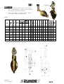
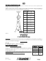
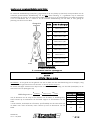
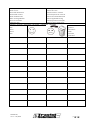
This total load value F varies with the angle (α) between the incoming and departing lines to the block. The
following Table 1 indicates the factor to be multiplied by the line pull to obtain the total load F on the block.
Table 1
Charge à la
suspente
α
Charge
Treuil
Angle α Effort applied on suspension « F »
0°
WLL winch x 2
15°
WLL winch x 1,98
30°
WLL winch x 1,95
45°
WLL winch x 1,85
60°
WLL winch x 1,73
90°
WLL winch x 1,41
120°
WLL winch x 1
150°
WLL winch x 0,52
180°
WLL winch x 0
Always ensure :F < pulley WLLF < anchoring point resistance.
IMPORTANT REMARK: In case on a 3 legs block assembly, add to the above calculated effort the load applied
on the becket. The total value of the calculated effort must be strictly lower to the working load limit (WLL)
of the block and the resistance of the anchorage point where the block is fitted.
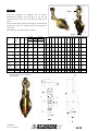
Example for EH
if α = 0°
F = 2 x winch WLL + becket loading
Wire rope strength reduction
Table 2
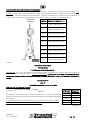
The ratio =
∅(
∅
/ ∅)
∅
between the pitch diameter of the sheave and the wire rope diameter, called the
winding ratio, alters the tensile strength in the wire rope as hereafter - Table 2
* Values for information only, depending on the construction of the wire rope.
For more information, please ask your wire rope supplier.
M 6062 M
rev 7 – 01/2015
Winding
Reduction
ratio
6
21%
8
17%
10
14%
15
11%
20
9%
p. 15 / 52