1
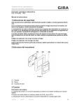
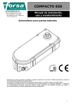
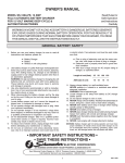
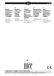
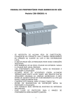
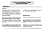
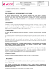
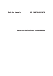
AUTOMATIONS FOR GATES
SISTEMA DE AUTOMATIZACIÓN PARA VERJAS
CON PUERTAS BATIENTES
R14BF / R14B
R14BENC
USE AND MAINTENANCE MANUAL
MANUAL DE USO Y MANTENIMIENTO
The manufacturer reserves the right to modify or improve them without prior notice.
Any inaccuracies or errors found in this manual will be corrected in the next edition.
When opening the packing please check that the product is in excellent condition.
Do not let children play anywhere there may be a suffocation hazard.
Please recycle materials in compliance with current regulations.
La empresa fabricante se reserva el derecho a aportar modificaciones o mejoras en el producto sin aviso previo.
Posibles errores o imprecisiones que se detecten en este manual se corregirán en el próximo.
Cuando abra el embalaje, compruebe la integridad del producto. No deje que los niños jueguen en zonas donde exista peligro de
ahogarse. Reciclar los materiales según las normativas vigentes.
1.4 TECHNICAL FEATURES
Power
Nominal speed
Absorbed rated current
Absorbed rated output
Nominal torque
Reduction ratio
Maximum gate length
Operating temperature
+60°C Weight
R14BF
12 V dc
1124 rpm
5.07 A
62 W
0.33 Nm
1/1098
1600 mm
from -20°C to +60°C
6.7 kg.
R14B
12 V dc
1124 rpm
5.07 A
62 W
0.33 Nm
1/1098
1600 mm
from -20°C to +60°C
6.7 kg.
R14 BENC
12 V dc
1400 rpm
2A
62 W
0.33 Nm
1/1098
1600 mm
from -20°C to
7.5 kg.
R14BF
12 V DC
1124 r.p.m.
5.07 A
62 W
0,33 Nm
1/1098
1600 mm
-20º ÷ 60 ºC
6.7 kg.
R14B
12 V DC
1124 r.p.m.
5.07 A
62 W
0,33 Nm
1/1098
1600 mm
-20º ÷ 60 ºC
6.7 kg.
R14BENC
12 V DC
1400 r.p.m.
2A
62 W Par
0,33 Nm
1/1098
1600 mm
-20°C ÷ 60°C
7.5 kg.
1.4 CARACTERÍSTICAS TÉCNICAS
Alimentación
Velocidad nominal
Corriente nominal absorbida
Potencia nominal absorbida
torsión nominal
Relación de reducción
Longitud máxima hoja puerta
Temperatura de trabajo
Peso
2
INSTALLATION MATERIAL (R14BF)
MATERIALES PARA LA INSTALACIÓN (R14BF)
1) Art. P-700SHOA4
: support with welded boss, 40 mm wide
Art. P-700SHOA5
: support with welded boss, 50 mm wide
2) Art. S-700CFR14B3 : bush
3) Art. S-700CFR1400 : bush seating ring
4) Art. S-700CFR14B : galvanized foundation box
5) Art. M-V45008035 : galvanized M8 x 35 screw
6) Art. M-300002003 : heath-shrinkable sheath
7) Art. P-650R14B
: R14BF geared motor
1) Art. P-700SHOA4
: soporte con bullón soldado ancho 40 mm.
Art. P-700SHOA5
: soporte con bullón soldado ancho 50 mm.
2) Art. S-700CFR14B3 : buje
3) Art. S-700CFR1400 : anillo compartimiento buje
4) Art. S-700CFR14B : caja cimentación galvanizada
5) Art. M-V45008035 : tornillo M8 x 35 galvanizado
6) Art. M-300002003 : conducto termo-restringible
7) Art. P-650R14B
Use the electric locks to lock the gates.
Utilizar la cerradura eléctrica para bloquear las hojas de la puerta
3
: grupo motorreductor R14BF
INSTALLATION MATERIAL (R14B)
MATERIALES PARA LA INSTALACIÓN (R14B)
1) Art. P-700SR14B
: support with manual unlock
2) Art. S-700CFR14B3 : bush
3) Art. S-700CFR1400 : bush seating ring
4) Art. S-700CFR14B
: galvanized foundation box
5) Art. M-V45008035
: galvanized M8 x 35 screw
6) Art. M-300002003
: health-shrinkable sheath
7) Art. P-650R14BSF
: R14B geared motor
1) Art. P-700SR14B
: soporte con bullón desbloqueo manual
2) Art. S-700CFR14B3 : buje
3) Art. S-700CFR1400 : anillo compartimiento buje
4) Art. S-700CFR14B
: caja cimentación galvanizada
5) Art. M-V45008035
: tornillo M8 x 35 galvanizado
6) Art. M-300002003
: conducto termo-restringible
7) Art. P-650R14BSF
: grupo motorreductor R14B
•
The reduction has no mechanical clutch. Use control units only with the electric clutch.
•
Grupo motorreductor sin embrague mecánico. Use exclusivamente paneles de control
con limitador eléctrico de par de motor.
4
INSTALLING THE FOUNDATION BOX
INSTALACIÓN DE LA CAJA DE CIMENTACIÓN
1. Take care to align gate axis
2. Make a really solid cement foundation
3. The drainpipe should drain water away outside
the foundation.
1.
2.
3.
4.
5
Vigilar la alineación con el eje de la verja
Efectuar una sólida cimentación con cemento
El tubo de drenaje del agua tiene que evacuar
fuera de la colada.
INSTALLING THE GEARED MOTOR AND COUPLING THE
GATE (R14B)
INTRODUCCIÓN DEL MOTORREDUCTOR Y ENGANCHE DE
LA HOJA DE LA PUERTA (R14B)
A.
B.
C.
D.
E.
F.
Gate
Support with manual unlock and lock
Bush
Bush seating ring
Foundation box cover
4 M8 x 35 screws for securing the
geared motor to the foundation box
G. Foundation box
H. Geared motor
A.
B.
Hoja de la puerta de la verja
Soporte con desbloqueo manual y
cerradura
C. Buje
D. Anillo compartimiento buje
E. Cubierta caja de cimentación
F. 4 tornillos M8 x 35 para sujetar el
motorreductor en la caja de cimentación
G. Caja de cimentación
H. Motorreductor
Weld support B to gate A accurately.
Soldar con mucho cuidado el soporte B en la hoja de la puerta A.
6
INSTALLING THE GEARED MOTOR AND COUPLING THE
GATE (R14BF)
INTRODUCCIÓN DEL MOTORREDUCTOR Y ENGANCHE DE
LA HOJA DE LA PUERTA (R14BF)
A.
B.
C.
D.
E.
F.
Gate
Support with boss
6.3 Ø self threading screw for securing gate
Bush
Bush seating ring
4 M8 x 35 screws for securing the geared
motor to the foundation box
G. Foundation box cover
H. Foundation box
I. Geared motor
A.
B.
C.
Hoja de la puerta de la verja
Soporte con buje
Tornillo auto-rosca de 6,3 de diámetro para
sujetar la hoja de la puerta
D. Buje
E. Anillo compartimiento buje
F. 4 tornillos M8 x 35 para sujetar el
motorreductor en la caja de cimentación
G. Cubierta caja de cimentación
H. Caja de cimentación
I. Motorreductor
Drill gate A using a 5.25 Ø bit and screw support B to it using screw C.
Perforar la hoja de la puerta con una broca de 5.25 mm de diámetro y atornillar el
soporte en la misma utilizando el tornillo C.
7
ELECTRICAL CONNECTION TO MOTOR
CONEXIÓN ELÉCTRICA CON EL MOTOR
Fit the wires inside the heat-shrinkable
sheath.
Introducir los cables en el conducto
termo-restringible.
Knot the ends of the wires together well.
Atar entre sí los extremos de los cables.
Place the sheath over the joins and heat
it.
Colocar el conducto sobre los empalmes
y calentarlo.
1. Use wires with the same thickness as that of the wires coming from the motor.
2. Make good joins.
3. Make sure the sheath is waterproof.
1. Usar cables que tengan el mismo espesor que los que salen del motor.
2. Efectuar correctamente el empalme.
3. Comprobar la estanqueidad del conducto.
ELECTRICAL CONNECTION TO MOTOR 12 V WITH ENCODER
CONEXIÓN ELÉCTRICA CON EL MOTOR 12 V CON ENCODER
The distance maximum between the control unit and the furthest motor must be no more than 10 meters.
Use cables with a cross section suitable for the motor's power, complying with current standards.
Wires of the photodiode encoder: white, brown, blue (0.5 mm2 cross section);
Motor phase wires: black, red ( 2.5 mm2 cross section);
The encoder's signal wires are to be connected to the MEC20 card connectors in the following way: brown - terminal 21, blue terminal 22, white 1st motor - terminal 23, white 2nd motor - terminal 24.Connect the black and red wires of the 1st motor to
terminals 7 and 8 and to terminals 9 and 10 those of the 2nd motor. Check that the required manoeuvre corresponds to an
opening input; to the contrary, reverse the position of the black-red wires.It is essential that the cross section of the wires must be
identical for connecting to the command card.
La distancia máxima entre la central y el motor más lejano no tiene que superar los 10 metros.
Use un cable de sección adecuada a la potencia del motor, respetando la Normativa vigente
Cables del encóder fotodiodo: blanco, marrón y azul (secc 0,5 mm2);
Cables de la fase del motor: negro y rojo (secc 2,5 mm2);
Los cables de señal del encóder se conectan a los conectores de la tarjeta MEC20 de la siguiente manera: marrón - borne 21,
azul - borne 22, blanco 1er. motor - borne 23, blanco 2do. motor - borne 24. Conecte los cables negro y rojo del 1er. motor a los
bornes 7-8 y los del 2do. motor a los bornes 9-10. Controle que a un input de apertura corresponda la maniobra deseada; en caso
contrario invierta la posición de los cables negro y rojo. Para las conexiones a la tarjeta de comando, use únicamente cables con
la misma sección.
8
ADJUSTING THE CLUTCH (R14BF)
AJUSTE DEL EMBRAGUE (R14BF)
Adjust torque until it is just enough to move
the gate; it must, in all cases, comply with
current regulations
Colocar un par como mínimo en el empuje
de la puerta y siempre de acuerdo con la
normativa vigente
USE OF MANUAL UNLOCKING (R14B)
UTILIZACIÓN DEL DESBLOQUEO MANUAL (R14B)
1.
2.
1.
2.
Pull cap A towards you to bring it to the
position shown in the Figure.
Place key in lock.
Tire hacia usted el tapón A y póngalo tal
como indica la figura.
Introduzca la llave en la cerradura.
When you remove the key the gate will be coupled again as soon as it is realigned with the geared motor.
Put the cap back on after you’ve taken the key out.
La extracción de la llave provocará el reenganche de la puerta apenas ésta se halle alineada con el motorreductor.
Vuelva a cerrar el tapón cuando haya sacado la llave.
9
GENERAL ADVICE
•
•
•
•
•
•
•
Install a gate safety system that complies with current regulations
Choose short routes for cables and keep power cables separate from control ones.
Install the control card in a waterproof box.
Please refer to current regulations when setting the geared motor’s maximum torque
We advise you to install an outdoor switch, in compliance with European standards on the issue of safety, to turn
the electricity off when servicing the gate.
Check that each single device installed is efficient and effective.
Affix easily readable signs, warning about the presence of a motorized gate.
RECOMENDACIONES DE CARÁCTER GENERAL
•
•
•
•
•
•
Integrar la seguridad de la verja con las normas vigentes
Elegir recorridos breves para los cables y mantener separados los cables de potencia de los de mando.
Instalar la ficha de mando dentro de una caja hermética.
Para la puesta a punto del par máximo motorreductor, respetar la normativa en vigor
De acuerdo con la normativa europea en materia de seguridad, se aconseja instalar un interruptor externo para
poder sacar la corriente cuando se deban realizar operaciones de mantenimiento de la verja. - Comprobar que
cada uno de los dispositivos funcione y sea eficaz.
Colocar carteles de fácil lectura y comprensión que informen de la presencia de una verja motorizada.
USE
The buried geared motor R14BF (R14B-R14BENC) is designed to move gates with a maximum opening length of 2
m (1.60 m).
It is categorically forbidden to use the geared motor for any other use or under circumstances different from those
mentioned herein.
The electronic unit (that must have the built-in electric clutch for the R14B version) normally makes it possible
for you to choose from:
automatic : a command pulse will open and shut the gate
semiautomatic : a command pulse will open or shut the gate
If there is a blackout the gate will work if it is equipped with a buffer battery; to control the gate manually first
operate the unlock mechanism for the R14B version.
Remember that this is an automatic device which is powered by electricity, consequently use with care. In
particular, remember:
•
•
•
•
•
•
•
•
•
•
never touch the device with wet hands and/or wet or bare feet
turn the electricity off prior to opening the command box and/or actuator
do not pull the lead to pull the plug out
do not touch the motor unless you are certain it is cold
put the gate in movement only when it is completely visible
keep out of the gate’s range of action if it is moving: wait until it has stopped
do not let children or animals play near the gate
do not let children, or incapable people, use the remote control or other operating devices
carry out routine maintenance
in the case of a failure, turn the electricity off and work the gate manually only if it is possible and safe. Refrain
from touching the gate and call an authorized technician
10
MODO DE EMPLEO
El motorreductor enterrado R14BF (R14B-R14BENC) se ha diseñado para mover verjas con una puerta batiente
máxima de 2 m (1.60 m).
Se advierte que está prohibido utilizar el aparato para otros usos o en circunstancias diferentes a las mencionadas.
Normalmente, la centralita electrónica instalada (que debe tener el limitador eléctrico de par incorporado en la
versión R14B) permite seleccionar el tipo de funcionamiento:
automático : un impulso del mando efectúa la abertura y el cierre de la verja
semiautomático : un impulso del mando efectúa la abertura o el cierre de la verja
En caso que faltara la energía eléctrica, la verja puede funcionar si dispone de una batería tampón; para que pueda
funcionar manualmente, extraer primero el desbloqueo en la versión R14B.
Se recuerda que nos hallamos ante un dispositivo automático alimentado por corriente eléctrica, por lo tanto, debe
usarse con precaución. En particular se recomienda:
•
•
•
•
•
•
•
•
•
•
No tocar el aparato con la manos mojadas y/o con los pies mojados o descalzos.
Desconectar la corriente antes de abrir la caja de mandos y/o el accionador .
No tirar del cable de alimentación para desconectar la toma de la corriente.
No tocar el motor si no está seguro que se haya enfriado completamente.
Mover la verja sólo cuando sea completamente visible.
Mantenerse fuera del radio de acción de la verja, si ésta se halla en movimiento, esperar hasta que se haya
detenido.
No dejar que niños o animales jueguen cerca de la verja.
No dejar que niños o personas incapacitadas usen el mando a distancia u otros dispositivos de accionamiento.
Realizar un mantenimiento periódico.
En caso de avería sacar la corriente y mover la verja manualmente sólo si es posible y seguro. Abstenerse de
realizar cualquier tipo de intervención, llamar a un técnico autorizado.
MAINTENANCE
The R14BF/R14B/R14BENC geared motor needs very little maintenance. However, the gate itself must be in good
condition if the geared motor is going to wear well, hence we shall describe briefly what you need to do to keep you
gate efficient at all times.
Attention: no one, except the person who services the equipment (who must be a specialized technician), should be
able to command the automatism during servicing. Consequently, it is advisable to turn the electricity off at the
mains (and disconnect the battery if present) also to avoid possible electric shocks. If the electricity has to be on
for certain checks, check or disable all command devices (remote controls, push button panels, etc.) except for the
device being used by the maintenance person.
Routine maintenance
Each of the following operations must be done when the need arises, but in all cases they should be done every six
months.
Gate
• Oil (with oiler) the hinges on which the gate swings
Automation unit
•
•
Check the proper working order of the safety devices (photoelectric cells, pneumatic edge, torque limiting device,
etc.) according to the manufacturers’ instructions
Check water tightness of joins of the motor’s cables
Extraordinary maintenance or serious failures
If serious servicing is needed on the electromechanical parts it is advisable to remove the geared motor so it can be
repaired in the workshop by the manufacturer’s technicians or by technicians authorized by the manufacturer.
11
MANTENIMIENTO
El motorreductor R14BF/R14B/R14BENC necesita poco mantenimiento. Sin embargo, su buen funcionamiento
depende también del estado de conservación de la verja, por ello pasamos a describir brevemente las operaciones
que se deben realizar para disponer de una verja en perfectas condiciones.
Atención!: Nadie a excepción del técnico de mantenimiento, que debe ser un técnico especializado, puede poner en
marcha el automatismo durante el mantenimiento. Por lo tanto se recomienda sacar la corriente de la red (y
desconecte la batería si estuviera presente), evitando de este modo el peligro de shock eléctrico. Si por el
contrario la corriente tuviera que estar presente para realizar algunas verificaciones, se recomienda controlar o
desactivar cada uno de los dispositivos de comando (mando a distancia, panel de mando, etc.), a excepción
del dispositivo que esté utilizando el técnico.
Mantenimiento ordinario
Cada una de las siguientes operaciones se debe realizar cada vez que sea necesario y como medida preventiva
cada seis meses.
Verja
•
Lubricar (con engrasador) los goznes sobre los que gira la verja.
Sistema de automatización
•
•
Comprobar el funcionamiento de los dispositivos de seguridad (fotocélulas, costa neumática, limitador de par,
etc...) según los tiempos y los modos suministrados por los fabricantes.
Comprobar la estanqueidad de los empalmes de los cables del motor.
Mantenimiento extraordinario y averías importantes
Si fuera necesario realizar intervenciones serias en las partes electromecánicas, se recomienda sacar el
motorreductor para que puedan ser reparadas en el taller por los técnicos de la casa central o por ésta autorizados.
TYPICAL SYSTEM
INSTALACIÓN TÍPICA
1.
2.
3.
4.
5.
6.
7.
1.
2.
3.
4.
5.
6.
7.
key selector
photoelectric cells
gates
buried geared motor
electric lock (not required for the
R14B version)
aerials and flashing light
control unit
Selector de llave
Fotocélulas
Batientes de la puerta
Motorreductor enterrado
Cerradura eléctrica (no necesaria
para R14B)
Antena y luz intermitente
Centralita
12
TYPICAL SYSTEM 12 V WITH ENCODER
INSTALACIÓN TÍPICA 12 V CON ENCODER
Distributed by:
Distribuido por:
3670 NW 79th Street
Miami, FL 33147
Phone: 305-691-7711
Fax: 305-693-1386
E-Mail: [email protected]
Web Site: www.AnchorMiami.com
13
1.
2.
3.
4.
5.
6.
7.
Gearmotor
Control unit
Key selector
Aerials and flashing light
Photoelectric cells
Pillars
Photoelectric cells
1.
2.
3.
4.
5.
6.
7.
Motorreductor
Centralita
Selector de llave
Antena y luz intermitente
Fotocélulas
Batientes
Fotocélulas