1
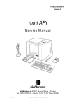
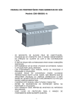
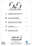
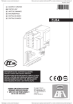
CENTRALE DI COMANDO
pag. 2
CONTROL UNIT
pag. 8
CENTRALE DE COMMANDE
pag. 14
DE
STEUERZENTRALE
pag. 20
ES
CENTRAL DE MANDO
pag. 26
IT
EN
FR
MANUALE D’INSTALLAZIONE ED USO
INSTALLATION AND OPERATION MANUAL
MANUEL D’ INSTALLATION ET D’ UTILISATION
INSTALLATIONS UND BEDIENUNGS
MANUAL D’ INSTALACION Y USO
DEC-SC
O&O S.r.l.
Via Europa, 2 - 42015 Correggio (R.E.) Italy - Phone 39 0522 740111 - Fax. 39 0522 631290
Internet: www.oeo.it - E-mail: [email protected]
Società soggetta ad attività di direzione e coordinamento di SOMFY S.A.
Company subject to management and coordination activities by SOMFY S.A.
Société sujette à des activités de direction et de coordination de SOMFY S.A.
Gesellschaft unter der Führung und Koordinierung von SOMFY S.A.
Sociedad sujeta a actividades de dirección y coordinación de SOMFY S.A.
Indice
Pagina
1. INTRODUZIONE
3
2. CARATTERISTICHE PRINCIPALI
3
3. CARATTERISTICHE TECNICHE
3
4. SICUREZZA DELL’INSTALLAZIONE
4
5. COLLEGAMENTI E FUNZIONALITA’ DI INGRESSI E USCITE
4
5.1 MORSETTIERA DI POTENZA J1 - J2
4
5.2 MORSETTIERA INGRESSI / USCITA IN BASSA TENSIONE J3
4
5.3 MORSETTIERA ANTENNA - COSTA J4
5
6. CONFIGURAZIONE DEI DIP-SWITCH
5
7. REGOLAZIONE DEI TRIMMER
5
8. RICEVENTE RADIO
6
8.1 DATI TECNICI RICEVENTE
6
8.2 FUNZIONALITÁ CANALE RADIO
6
8.3 INSTALLAZIONE ANTENNA
6
8.4 PROGRAMMAZIONE MANUALE
6
8.5 PROGRAMMAZIONE MODALITÁ AUTOAPPRENDIMENTO
6
9. AVVERTENZE
6
TABELLA A
7
-2-
DEC-SC
IT
Istruzioni per installazione ed uso
1. INTRODUZIONE
La centrale di comando DEC-SC è stata sviluppata per gestire le automazioni SMART-800 e MEGA 2000 per cancelli scorrevoli.
La notevole disponibilità di logiche selezionabili, consente di soddisfare anche particolari condizioni operative sugli impianti.
2. CARATTERISTICHE PRINCIPALI
- Logica a microprocessore
- Led che visualizzano lo stato degli ingressi
- Morsettiere estraibili sugli ingressi in bassa tensione
- Frenatura elettrica a finecorsa per cancelli con particolare numero di cicli ed inerzia
- Uscita spia cancello aperto
- Ricevente radio 433MHz integrata
LED
J1:
Morsettiera motore
J2:
Morsettiera di potenza
J3:
Morsettiera ingressi/uscite bassa tensione
J4:
Morsettiera antenna - costa
SW1:
Tasto di comando “START”
SW2:
Tasto di comando “AP.PED”
SW3:
Dip Switch
P1:
Trimmer coppia
P2:
Trimmer tempo pausa
F1:
Fusibile linea 6.3A
F2:
Fusibile bassa tensione da 100mA
3. CARATTERISTICHE TECNICHE
- Alimentazione:
- Uscita motore:
- Uscita lampeggiante:
- Uscita SCA:
- Uscita accessori 24Vac:
230Vac ±10% 50 Hz.
230Vac; 1,5A max
230Vac; 40W max
24Vac 3W max
3W max
-3-
4. SICUREZZA DELL’INSTALLAZIONE
Affinché si raggiunga il grado di sicurezza richiesto dalla normativa vigente, leggere attentamente le seguenti prescrizioni.
1) Realizzare tutti i collegamenti in morsettiera leggendo attentamente le indicazioni riportate in questo manuale ed osservando le norme
generali e di buona tecnica che regolano l’esecuzione degli impianti elettrici.
2) Predisporre a monte dell’installazione un interruttore magnetotermico omnipolare con distanza di apertura dei contatti di min. 3 mm.
3) Installare, ove non sia previsto, un interruttore differenziale con soglia 30 mA.
4) Verificare l’efficacia dell’impianto di messa a terra e collegare a questa tutte le parti dell’automazione provviste di morsetto o cavo di
terra.
5) Prevedere la presenza di almeno un dispositivo di segnalazione esterna, di tipo semaforico o lampeggiante, affiancato da un cartello
segnaletico di pericolo o di avviso.
6) Applicare tutti i dispositivi di sicurezza richiesti dalla tipologia dell’installazione considerando i rischi che essa può causare.
7) Separare nelle canalizzazioni le linee di potenza (sez. min. 1,5 mm2) da quelle di segnale in bassa tensione (sez. min. 0,5 mm2).
8) Ponticellare gli ingressi N.C. non utilizzati.
9) Disporre in serie eventuali contatti da collegare in serie allo stesso ingresso N.C.
10) Disporre in parallelo gli ingressi collegati al medesimo ingresso N.A.
5. COLLEGAMENTI E FUNZIONALITA’ DI INGRESSI E USCITE
5.1 MORSETTIERA DI POTENZA J1 - J2
L N E
SMART-800
LINEA 230V
Alimentazione a 230V 50Hz con protezione interna a mov e fusibile (5x20) da 6.3A.
Collegare la fase ed il neutro come riportato in serigrafia. Utilizzare un cavo tipo H07RN-F 2x1,5+T min.
Collegare il conduttore giallo/verde della rete di alimentazione al morsetto di terra dell’apparecchio.
J1
LAMP
SL-R-AI
LAMPEGGIANTE: LUCE GIALLA a 230V 40W max.
N
J2
INVERSIONE SENSO DI ROTAZIONE MOTORE
5.2 MORSETTIERA INGRESSI/USCITE IN BASSA TENSIONE J3
COM
24Vac
OUT 24V
Uscita a 24Vac per alimentare accessori di sicurezza e comando come fotocellule o ricevitori radio.
SCA
COM
COM
COM
STOP
START
SCA
Spia carraio aperto. Con quattro segnalazioni differenti indica lo stato dell’automazione:
Lampeggio lento:
fase di apertura
Lampeggio veloce:
fase di chiusura
Luce fissa:
cancello aperto o anche fermo in apertura parziale
Luce spenta:
cancello chiuso
Lampeggio doppio:
costa di sicurezza premuta
START
Ingresso N.A. che consente di comandare l’automazione secondo la logica programmata tramite i dip 1, 2, 3, 4
Se a cancello chiuso viene mantenuto attivato il comando di start si ottiene l’apertura totale, con tipologia di funzionamento
a orologio, e quando lo si libera dopo il tempo di pausa impostato su P2, viene effettuata la chiusura.
STOP
Ingresso N.C. di sicurezza. Quando viene attivato arresta immediatamente l’automazione e uno start successivo provoca
sempre una riapertura.
Durante il tempo di pausa un comando di stop elimina la richiusura automatica restando in attesa di comandi.
-4-
ANTENNA
COSTA
COM
INGRESSI finecorsa
Ingressi N.C.
Qualora si inverta il senso di rotazione del motore, ricordarsi di invertire FCA/FCC.
SHIELD
COM
COM
AP. PED
Ingresso N.A. di start pedonale. Consente l’apertura parziale di 10 sec. secondo la logica programmata tramite i dip 1 e 2.
Se a cancello chiuso viene mantenuto attivato il comando di start pedonale si ottiene l’apertura parziale, con tipologia di funzionamento a orologio, e quando lo si libera dopo 10 sec. di pausa viene effettuata la chiusura (dip 1- 2 ON).
COM
FOTO
AP. PED
FCC
FCA
COSTA
FOTO
Ingresso N.C. di sicurezza. Quando viene attivato in fase di chiusura provoca la riapertura dell’automazione. Se viene abilitato
anche in apertura tramite il dip 5, ferma temporaneamente l’automazione per il tempo in cui è impegnato.
5.3 MORSETTIERA ANTENNA - COSTA J4
INGRESSO COSTA DI SICUREZZA
Tramite il dip 6 è possibile selezionare l’intervento della costa di sicurezza sia N.C. che a contatto resistivo
8,2kΩ.
6. CONFIGURAZIONE DEI DIP SWITCH
Dip switch n° 1 e 2: Selezionano la logica di funzionamento
Off-Off: Logica a uomo presente.
L’automazione funziona per comandi mantenuti.
Il comando di start una volta apre e una volta chiude.
La normativa vieta comandi via radio nella logica a uomo presente.
Off-On: Logica semiautomatica.
L’automazione funziona per comandi ad impulsi senza la richiusura automatica.
Quindi a fine apertura, sia nel ciclo normale che pedonale, per comandare la chiusura occorre agire rispettivamente sullo start o start
pedonale.
On-Off: Logica automatica tipo 1.
L’automazione funziona per impulsi.
Nel ciclo normale terminata la fase di apertura è attivata la richiusura automatica dopo il tempo impostato sul trimmer P2.
Nel ciclo parziale (pedonale) la logica è semiautomatica, quindi al termine dell’apertura per chiudere occorre un impulso sull’ingresso
di start ped.
On-On: Logica automatica tipo2.
L’automazione funziona per impulsi. Nel ciclo normale al termine della fase di apertura è attivata la richiusura automatica dopo il tempo
impostato sul trimmer P2.Nel ciclo parziale (pedonale) la logica è automatica con un tempo pausa fisso di 10 sec.
- Il comando di START è sempre prioritario sul ciclo di apertura parziale realizzando l’apertura totale del serramento.
- Nel caso in cui l’automazione si trovi in condizioni di black-out sul finecorsa di apertura (FCA), se la logica è impostata in modalità
automatica, al ritorno della corrente il cancello si richiuderà dopo 3 sec.
Dip switch n° 3 e 4: Selezionano la risposta della logica alla sequenza di comandi di start.
Off-Off: Passo-passo tipo1: apre-stop-chiude-stop-apre-stop-chiude
Off-On: Passo-passo tipo2: apre-stop-chiude-apre-stop-chiude-apre
On-Off: Condominiale tipo1: comando di sola apertura, in pausa uno start chiude ed in chiusura riapre.
On-On: Condominiale tipo2: comando di sola apertura, in pausa lo start non viene considerato ed in chiusura riapre.
Dip 5 Off: Fotocellule attive solo in chiusura: in caso di oscuramento invertono la manovra.
Dip 5 On: Fotocellule attive sia in chiusura che in apertura: se le fotocellule vengono oscurate sia in fase di chiusura che di apertura,
l’automazione si arresta fino a quando non vengono liberate per poi effettuare sempre l’apertura.
Dip 6 Off: Costa sensibile a contatto N.C.
Dip 6 On: Costa di sicurezza a contatto resistivo da 8,2kΩ.
Dip 7 Off: Prelampeggio escluso.
Dip 7 On: Prelampeggio di 2 sec. inserito.
Dip 8 Off: Frenatura elettrica a finecorsa esclusa.
Dip 8 On: Frenatura elettrica a finecorsa attivata.
7. REGOLAZIONE DEI TRIMMER
P1 “COPPIA”: Imposta il valore di coppia utile per muovere il serramento dopo lo spunto di 1,5 sec. a potenza massima.
(Tensione regolabile da 120÷230V).
P2 “T.PAUSA”: Imposta il tempo di pausa da 2÷120 sec.
Il tempo di lavoro è preimpostato a 90 sec. di manovra utile, oltre alla quale si arresta il motore.
-5-
8. RICEVENTE RADIO
8.1 DATI TECNICI RICEVENTE
- N° max radiotrasmettitori memorizzabili:
- Frequenza:
- Codice a mezzo:
- N°combinazioni:
64
433.92MHz
Algoritmo rolling-code
4 miliardi
8.2 FUNZIONALITÁ CANALE RADIO
Canale radio 1:
Canale radio 2:
Invia il comando di START
Invia il comando di apertura pedonale AP.PED
8.3 INSTALLAZIONE ANTENNA
Usare una antenna accordata sui 433MHz.
Collegare l’antenna sui morsetti antenna
utilizzando un cavo coassiale RG58 .
ANTENNA
COSTA
SHIELD
cavo antenna RG58
8.4 PROGRAMMAZIONE MANUALE
Nel caso di installazioni standard nelle quali non siano richieste le funzionalità avanzate è possibile procedere alla memorizzazione manuale dei trasmettitori, facendo riferimento alla tabella di programmazione A
per la programmazione base.
1) Se si desidera che il trasmettitore attivi il canale 1 premere il pulsante PR1, oppure se si desidera che il
trasmettitore attivi il canale 2 premere il pulsante PR2.
2)Al lampeggio del led DL1 premere il tasto nascosto del trasmettitore, il led DL1 resterà acceso fisso.
3) Premere il tasto da memorizzare del trasmettitore, il led DL1 lampeggerà velocemente indicando l’avvenuta memorizzazione. In seguito riprenderà il lampeggio normale.
4)Per memorizzare un ulteriore trasmettitore ripetere i passi 3) e 4).
5) Per uscire dal modo di memorizzazione attendere fino al completo spegnimento del led oppure premere
il tasto di un telecomando appena memorizzato.
NOTA IMPORTANTE: CONTRASSEGNARE IL PRIMO TRASMETTITORE MEMORIZZATO CON IL BOLLINO CHIAVE (master).
Il primo trasmettitore, nel caso di programmazione manuale, assegna il codice chiave al ricevitore; questo
codice risulta necessario per poter effettuare la successiva clonazione dei radiotrasmettitori.
Tasto nascosto
8.5 PROGRAMMAZIONE MODALITÁ AUTOAPPRENDIMENTO
Questo modalità serve per eseguire una copia dei tasti di un trasmettitore già memorizzato nella ricevente
senza accedere alla ricevente.
Il primo trasmettitore deve essere memorizzato in modo manuale (vedi paragrafo 8.4).
a) Premere il tasto nascosto del trasmettitore già memorizzato.
b) Premere il tasto T del trasmettitore già memorizzato che si desidera attribuire anche al nuovo trasmettitore.
c) Premere entro 10s, il tasto nascosto del nuovo trasmettitore da memorizzare.
d) Premere il tasto T che si desidera attribuire al nuovo trasmettitore.
e) Per memorizzare un’altro trasmettitore, ripetere dal passo (c) entro un tempo max di 10 secondi, altrimenti
la ricevente esce dal modo programmazione.
f) Per copiare un altro tasto, ripetere dal passo (a) attendendo l’uscita dal modo programmazione (o togliendo
alimentazione alla ricevente).
Tasto nascosto
9. AVVERTENZE
Si raccomanda di eseguire un’installazione che preveda tutti gli accessori necessari ad assicurare il funzionamento secondo normativa
vigente, impiegando sempre dispositivi originali O&O.
L’utilizzo e l’installazione di queste apparecchiature deve rispettare rigorosamente le indicazioni fornite dal costruttore che non può essere
considerato responsabile per eventuali danni derivanti da uso improprio o irragionevole.
La O&O srl declina ogni responsabilità per le possibili inesattezze contenute nel seguente pieghevole e si riserva il diritto di apportare
modifiche in qualsiasi momento senza preavviso alcuno.
-6-
-7-
Contents
Page
1. INTRODUCTION
9
2. MAIN CHARACTERISTICS
9
3. TECHNICAL SPECIFICATIONS
9
4. INSTALLATION SAFETY
10
5. INPUT AND OUTPUT FUNCTIONALITY AND CONNECTIONS
10
5.1 J1 - J2 POWER TERMINAL BLOCK
10
5.2 J3 LOW VOLTAGE INPUT/OUTPUT TERMINAL BLOCK
10
5.3 J4 TERMINAL BLOCK SAFETY EDGE - ANTENNA
11
6. DIP-SWITCH CONFIGURATION
11
7. TRIMMER ADJUSTMENT
11
8. RADIO RECEIVER
12
8.1 RECEIVER TECHNICAL SPECIFICATIONS
12
8.2 RADIO CHANNEL FUNCTIONALITY
12
8.3 ANTENNA INSTALLATION
12
8.4 MANUAL PROGRAMMING
12
8.5 SELF-LEARNING MODE PROGRAMMING
12
9. ATTENTION
12
TABLE A
13
-8-
DEC-SC
Instructions for installation and use
1. INTRODUCTION
The DEC-SC control unit has been designed to control the automations SMART-800 and MEGA 2000 for sliding doors.
The considerable number of logic units available permits satisfying even special operating conditions on systems.
2. MAIN CHARACTERISTICS
- Microprocessor logic
- LEDs displaying input status
- Extractable terminal boards on low voltage inputs
- Electric braking with limit switches for gates with special number of cycles and inertia
- Output for gate open indicator light
- Integrated radio receiver 433Mhz
LED
J1:
Terminal board
J2:
Power terminal block
J3:
Low voltage input/output terminal board
J4:
Terminal Block Safety edge and Antenna
SW1:
“START” control button
SW2:
“AP.PED” control button
SW3:
Dip Switch
P1:
Torque trimmer
P2:
Pause time trimmer
F1:
Line fuse 6.3A
F2:
Low tension fuse 100mA
3. TECHNICAL SPECIFICATIONS
- Power supply:
- Motor output:
- Traffic light:
- SCA output:
- Accessory output 24Vac:
-9-
230Vac ±10% 50 Hz.
230Vac; 1,5A max
230Vac; 40W max
24Vac 3W max
3W max
EN
4. INSTALLATION SAFETY
In order to reach the level of safety required by current regulations, read the following prescriptions carefully.
1) Make all the connections in the terminal block after carefully reading the instructions given in this manual and observing the general
rules and technical standards governing electrical systems.
2) Upstream from the installation, fit an omnipole miniature circuit breaker with a contact gap of at least 3 mm.
3) If there isn’t one already, install a residual current device with a threshold of 30 mA.
4) Check the effectiveness of the grounding system and connect to it all the parts of the automation fitted with a terminal or grounding
cable.
5) Fit at least one external warning device, such as a traffic light or flashing light, along with a warning or danger sign.
6) Fit all the safety devices required by the type of installation, taking into consideration the risks it can cause.
7) Separate the power lines (min. sect. 1.5 mm ) from the low-voltage signal lines (min. sect. 0,5 mm ) in the ducts.
8) Fit jumpers in the N.C. inputs not used.
9) Set in series any contacts to be connected in series with the same N.C. input.
10)Set in parallel the inputs connected to the same N.O. input.
2
2
5. INPUT AND OUTPUT FUNCTIONALITY AND CONNECTIONS
5.1 J1 - J2 POWER TERMINAL BLOCK
SMART-800
L N E
LINE 230V
230V 50Hz power supply with mov internal protection and 6,3A fuse (5x20).
Connect the phase and neutral as shown on the screen printing. Use a cable type H07RN-F 2x1.5+E min.
Connect the yellow/green wire of the power supply mains to the earth terminal of the appliance.
J1
LAMP
SL-R-AI
FLASHING LIGHT: YELLOW at 230V 40W max.
N
J2
SWITCH THE MOTOR ROTATION
5.2 J3 LOW VOLTAGE INPUT/OUTPUT TERMINAL BOARD
COM
24Vac
OUT 24V
24Vac output to power safety and control accessories such as photoelectric cells or radio receivers.
SCA
COM
COM
START
N.O. input used to control the automation according to the programmed logic with the dip switches 1, 2, 3, 4
If the start control is kept active with the gate closed, there is total opening, with timer-type operation, and when it is freed
after the pause time set on trimmer P2, the gate is closed.
COM
STOP
START
SCA
Passageway open indicator light. With four different indicators it shows the automation status:
Slow blinking:
opening phase
Fast blinking:
closing phase
Steady light:
gate open or even stopped with partial opening
Light off:
gate closed
Double Flashing: safety edge squeezed
STOP
N.C. safety input. When it is activated it stops the automation immediately and a subsequent start always causes a
reopening. During the pause time (trimmer P2) a stop control eliminates automatic reclosure, leaving the gate open waiting
for commands.
- 10 -
COM
COM
AP.PED
Pedestrian start N.O. input. Allows 10 sec partial opening according to the logic programmed with the dip switches 1-2.
If the pedestrian start control is kept active with the gate closed, there is partial opening, with timer-type operation, and
when it is freed after a pause the gate is closed (dip 1 - 2 ON).
COM
FOTO
AP. PED
FCC
FCA
FOTO
N.C. safety input. When it is activated in the closing phase it causes the automation to reopen. If it is enabled also in the opening phase with dip switch 5, it temporarily stops the automation for the time for which it is engaged.
LIMIT SWITCH INPUT
N.C. inputs.
If the direction of rotation is reversed, reverse FCA/FCC.
ANTENNA
COSTA
SHIELD
COM
COSTA
5.3 J4 TERMINAL BLOCK SAFETY EDGE - ANTENNA
SAFETY EDGE INPUT
Trough Dip Switch 6 is possible to select the activation of the safety edge both in N.C. contact and/or
resistive contact 8,2kΩ
6. DIP-SWITCH CONFIGURATION
Dip switches 1 and 2: Select the functioning logic
Off-Off: Dead-man logic
The automation works for held controls.
The start control opens once and closes once.
Regulations prohibit controls via radio with dead-man logic.
Off-On: Semiautomatic logic.
The automation works for pulse controls without automatic reclosing.
So at the end of opening, in both the normal and pedestrian cycle, to control closure it is necessary to use respectively the start or
pedestrian start.
On-Off: Automatic logic type 1.
The automation works with pulses.
In the normal cycle, after the opening phase, automatic closing is activated after the time set on trimmer P2.
In the partial (pedestrian) cycle, the logic is semiautomatic so, at the end of opening, a pulse on the start ped.
On-On: Automatic logic type 2.
The automation works with pulses. In the normal cycle, at the end of the opening phase, automatic closing is activated after the time
set on trimmer P2.
In the partial (pedestrian) cycle, the logic is automatic with a fixed pause time of 10 sec.
- The START control always takes priority over the partial opening cycle with full gate opening.
- If the automation is in a state of black-out on the opening limit switch (FCA), if the logic is set in automatic mode, when power is
restored the gate will close after 3 sec.
Dip switch 3 and 4: Select the response of the logic to the sequence of start controls.
Off-Off: Step-by-step type 1: open-stop-close-stop-open-stop-close
Off-On: Step-by-step type 2: open-stop-close-open-stop-close-open
On-Off: Condominium type 1: control for opening only, on pause a start closes and on closure it reopens.
On-On: Condominium type 2: control for opening only, on pause the start is not considered and on closure it reopens.
Dip 5 Off: Photocells active only on closing: if obscured they reverse the direction.
Dip 5 On: Photocells active on both closing and opening: if the photocells are obscured in either the closing or opening phase, the
automation stops until they are freed to then open.
Dip 6 Off: Safety edge with NC contact.
Dip 6 On: Safety edge with 8,2kΩ resistive contact
Dip 7 Off: Pre-flashing off.
Dip 7 On: Pre-flashing of 2 sec. on.
Dip 8 Off: Electric braking at limit switch off.
Dip 8 On: Electric braking at limit switch on.
7. TRIMMER ADJUSTMENT
P1 “TORQUE”: Sets the useful torque to move the gate after starting for 1,5 sec. at full power.
(Adjustable voltage from 120 to 230V).
P2 “T.PAUSE”: Sets the pause time from 2 to 120 sec.
Operation time is set at 90 secs (working manoeuvre). The motor stops after this time.
- 11 -
8. RADIO RECEIVER
8.1 RECEIVER TECHNICAL SPECIFICATIONS
- Max. n° of radio transmitters that can be memorized:
- Frequency:
- Code by means of:
- N° of combinations:
64
433.92MHz
Rolling-code algorithm
4 billion
8.2 RADIO CHANNEL FUNCTIONALITY
Channel 1:
Channel 2:
Start command
AP.PED command (Pedestrian Opening)
8.3 ANTENNA INSTALLATION
ANTENNA
COSTA
SHIELD
Use an antenna tuned to 433MHz. Connect the
tuned antenna to the antenna terminals using
RG58 coaxial cable .
antenna cable RG58
8.4 MANUAL PROGRAMMING
In the case of standard installations where no advanced functions are required, it is possible to proceed to
manual storage of the transmitters, making reference to programming table A and to the example for basic
programming.
1) If you wish the transmitter to activate output 1, press pushbutton PR1, otherwise if you wish the
transmitter to activate output 2, press pushbutton PR2.
2) When LED DL1 starts blinking, press hidden key on the transmitter, LED DL1 will remain continuously lit.
3) Press the key of the transmitter to be memorized, LED DL1 will flash quickly to indicate that it has been
memorized successfully. Flashing as normal will then be resumed.
4) To memorize another transmitter, repeat steps 2) and 3).
5) To exit memorizing mode, wait for the LED to go off completely or press the key of a remote control that has just been memorized.
IMPORTANT NOTE: ATTACH THE ADHESIVE KEY LABEL TO THE FIRST MEMORISED TRANSMITTER
(MASTER).
In the case of manual programming, the first transmitter assigns the key code to the receiver; this code is
necessary in order to carry out subsequent cloning of the radio transmitters.
Hidden key
8.5 SELF-LEARNING MODE PROGRAMMING
This mode is used to copy the keys of a transmitter already stored in the receiver memory, without accessing the receiver.
The first transmitter is to be memorised in manual mode (see paragraph 8.4).
a) Press hidden key on the transmitter already memorised.
b) Press key T on the transmitter already memorised, which is also to be attributed to the new transmitter.
c) Within 10 s., press hidden key on the new transmitter to be memorised.
d) Press key T to be attributed to the new transmitter.
e) To memorise another transmitter, repeat the procedure from step (c) within a maximum time of 10
seconds, otherwise the receiver exits the programming mode.
f ) To copy another key, repeat from step (a), having waited for the receiver to exit the programming mode
(or after disconnecting the receiver from the power supply).
Hidden key
9. ATTENTION
It is recommended to make an installation which has all the accessories necessary to ensure operation according to current provisions,
always using genuine O&O devices.
This equipment must be installed and used in strict compliance with the manufacturer’s instructions. The manufacturer cannot be held
responsible for any damage deriving from improper or unreasonable use.
O&O srl disclaims all liability for any inaccuracies contained in this booklet and reserves the right to make changes at any time without
any prior notice whatsoever.
- 12 -
- 13 -
Sommaire
Page
1. AVANT-PROPOS
15
2. CARACTERISTIQUES PRINCIPALES
15
3. CARACTERISTIQUES TECHNIQUES
15
4. SECURITE DE L’INSTALLATION
16
5. CONNEXIONS ET DESCRIPTION DES ENTRÉES ET DES SORTIES
16
5.1 BORNIER D’ALIMENTATION J1 - J2
16
5.2 BORNIER ENTREES/SORTIES A BASSE TENSION J3
16
5.3 BORNIER D’ANTENNE ET LISTEL DE SÉCURITÉ J4
17
6. CONFIGURATION DES MICROINTERRUPTEURS
17
7. REGLAGE DES POTENTIOMÈTRES
17
8. RECEPTEUR RADIO
18
8.1 DONNÉES TECHNIQUES RECEPTEUR
18
8.2 FONCTION CANAL RADIO
18
8.3 INSTALLATION ANTENNE
18
8.4 PROGRAMMATION MANUELLE
18
8.5 PROGRAMMATION MODALITÉ AUTO-APPRENTISSAGE
18
9. MISE EN GARDE
18
TABLEAU A
19
- 14 -
DEC-SC
FR
Mode d’emploi
1. AVANT-PROPOS
La centrale de commande DEC-SC a été développée pour le contrôle de automatisme SMART-800 et MEGA 2000 pour portes coulissantes. La grande disponibilité de logiques sélectionnables permet de satisfaire les conditions particulières d’exercice des installations.
2. CARACTERISTIQUES PRINCIPALES
- Logique à microprocesseur
- Diodes qui affichent l’état des entrées
- Borniers extractibles sur les entrées à basse tension.
- Freinage électrique à fin de course pour portes à nombre de cycles et inertie particuliers.
- Sortie pour voyant lumineux portail ouvert.
- Radio récepteur 433 MHz intégrée
LED
J1:
Bornier moteur/condensateur
J2:
Bornier d’alimentation
J3:
Bornier entrées/sorties à basse tension
J4:
Bornier listel de sécurité et d’antenne
SW1:
Touche de commande “START”
SW2:
Touche de commande “AP.PED”
SW3:
Microinterrupteur
P1:
Potentiomètre couple
P2:
Potentiomètre temps de pause
F1:
Fusible ligne 6.3A
F2:
Fusible de basse tension a 100mA
3. CARACTERISTIQUES TECHNIQUES
- Alimentation:
- Sortie moteur:
- Sortie clignotant:
- Sortie SCA:
- Sortie accessoires 24Vca.
- 15 -
230Vac ±10% 50 Hz.
230Vac; 1,5A max
230Vac; 40W max
24Vac 3W max
3W max
4. SECURITE DE L’INSTALLATION
Pour atteindre le degré de sécurité requis par la législation en vigueur, lisez attentivement et suivez les prescriptions suivantes
1) Tous les branchements dans le bornier doivent être effectués après avoir lu attentivement les indications reportées dans ce mode d’emploi
et en suivant les règles générales et de bonne technique qui règlent la réalisation des installations électriques.
2) Prévoyez en amont de l’installation un disjoncteur omnipolaire avec une distance d’ouverture des contacts de 3 mm min.
3) Installez, où il n’est pas prévu, un interrupteur différentiel avec un seuil de 30 mA.
4) Vérifiez l’efficacité de la mise à la terre et reliez-y tous les composants de l’automation dotés d’une borne ou d’un fil de terre.
5) Prévoyez la présence d’au moins un signal externe de type “feux rouges” ou clignotant ainsi qu’un panneau signalant le danger ou
d’avertissement.
6) Appliquez tous les dispositifs de sécurité requis par le type d’installation en prenant en compte les risques qu’elle peut provoquer.
7) Dans les goulottes, séparez les lignes d’alimentation (sec. min. 1,5 mm2) de celles de signal en basse tension (sec. min. 0,5 mm2).
8) Court-circuitez les entrées N.F. inutilisées.
9) Disposez en série les contacts éventuels à brancher en série à la même entrée N.F.
10) Disposez en parallèle les entrées reliées à la même entrée N.O.
5. CONNEXIONS ET DESCRIPTION DES ENTRÉES ET DES SORTIES
5.1 BORNIER D’ALIMENTATION J1 - J2
LIGNE 230V
Alimentation à 230V 50Hz avec protection interne à mov et fusible (5x20) de 6,3A.
Branchez la phase et le neutre comme reporté sur la plaquette. Utilisez un câble type H07RN-F 2x1,5+T min.
SMART-800 Brancher le conducteur jaune/vert du réseau d’alimentation à la borne deterre de l’appareil.
L N E
J1
LAMP
SL-R-AI
CLIGNOTANT: FEU JAUNE à 230V 40W max.
N
J2
INVERSION DIRECTION DE ROTATION MOTEUR
5.2 BORNIER ENTREES/SORTIES A BASSE TENSION J3
COM
24Vac
OUT 24V
Sortie à 24Vac pour alimenter les accessoires de sécurité et de commande comme les photocellules ou les récepteurs
radio.
SCA
COM
START
Entrée N.O. permettant de commander l’automation selon la logique programmée avec les microinterrupteurs 1, 2, 3, 4.
Si la commande de start piétonnier est maintenue activée lorsque le portail est fermé, on obtient l’ouverture partielle, avec
un type de fonctionnement à horologe.
La fermeture s’obtient après de le temps, de pause point sur le potentiomètre P2, avoir relâché la commande.
COM
COM
STOP
Entrée N.F. de sécurité. Son activation arrête immédiatement l’automation et un start successif provoque toujours une
rouverture. Pendant le temps de pause (potentiomètre P2) une commande de stop élimine la refermeture automatique en
laissant le portail ouvert dans l’attente de commandes.
COM
FOTO
STOP
START
SCA
Signal passage pour véhicules ouvert. Les quatre signalisations différentes indiquent l’état de l’automation:
Clignotement lent:
phase d’ouverture
Clignotement rapide:
phase de fermeture
Feu fixe:
portail ouvert ou arrêté en ouverture partielle
Feu éteint:
portail fermé
Double flash:
bord sensible écrasé
FOTO
Entrée N.F. de sécurité. Son activation en phase de fermeture provoque la rouverture de l’automation. Si elle est activée
en ouverture aussi avec le microinterrupteur 5, elle arrête temporairement l’automation pendant la durée où il est excité.
- 16 -
COM
COM
AP. PED
FCC
FCA
AP.PED
Entrée N.O. de start piétonnier. Permet l’ouverture partielle de 10 sec. selon la logique programmée avec les microinterrupteurs 1 et 2. Si la commande de start piétonnier est maintenue activée lorsque le portail est fermé, on obtient l’ouverture
partielle, avec un type de fonctionnement à horologe.
La fermeture s’obtient 10 secondes après avoir relâché la commande (dip 1 - 2 ON).
ENTRÉE FIN DE COURSE
Entrées N.F..
En cas d’inversion du sens de rotation du moteur, ne pas oublier d’inverser FCA/FCC.
ANTENNA
COSTA
SHIELD
COM
COSTA
5.3 BORNIER D’ANTENNE ET LISTEL DE SÉCURITÉ J4
ENTRÉE LISTEL DE SÉCURITÉ
Avec le DIP 6, vous pouvez sélectionner le borde sensible soit en N.F. que avec le contact conducteur
résistive de 8,2kΩ.
6. CONFIGURATION DES MICROINTERRUPTEURS
Microinterrupteurs n° 1 et 2: Ils sélectionnent la logique de fonctionnement
Off-Off: Logique “homme présent”.
L’automation fonctionne par commandes maintenues.
L’actionnement de start provoque une ouverture et une fermeture.
La législation interdit les commandes via radio dans la logique “homme présent”.
Off-On: Logique semi-automatique.
L’automation fonctionne par impulsions sans la refermeture automatique.
A la fin de l’ouverture, que ce soit en cycle normal ou piétonnier, pour commander la fermeture, il faut agir respectivement sur le start
ou le start piétonnier.
On-Off: Logique automatique type 1.
L’automation fonctionne par impulsions. Pendant le cycle normal, après la phase d’ouverture, la refermeture automatique est activée
après le délai mis au point sur le potentiomètre P2. Pendant le cycle partiel (piétonnier) la logique est semi-automatique, par conséquent
pour fermer après l’ouverture, il faut donner une impulsion sur l’entrée de start piét.
On-On: Logique automatique type 2.
L’automation fonctionne par impulsions. Pendant le cycle normal, la refermeture automatique est activée après le délai mis au point sur
le potentiomètre P2.Pendant le cycle partiel (piétonnier)la logique est automatique avec un temps de pause fixe de 10 sec.
- Le commande de START est toujours prioritaire sur le cycle d’ouverture partielle en réalisant l’ouverture totale du portail.
- En cas d’interruption de courant sur le microinterrupteur d’ouverture (FCA), si la logique est sélectionnée en modalité automatique, le
portail se fermera après le temps de pause prévu 3 sec.
Microinterrupteurs 3 et 4: Ils sélectionnent la réponse de la logique à la séquence de commandes de start.
Off-Off: Pas-pas type 1: ouverture-stop-fermeture-stop-ouverture-stop-fermeture
Off-On: Pas-pas type 2: ouverture-stop-fermeture-ouverture-stop-fermeture-ouverture
On-Off: Copropriétés type 1: commande d’ouverture seulement, en pause un start fermeture et en fermeture il rouvre.
On-On: Copropriétés type 2: commande d’ouverture seulement, en pause le start n’est pas pris en considération et il rouvre en fermeture.
Dip 5 Off: Photocellules activées en fermeture seulement: en cas d’interruption de leur faisceau, elles inversent la manœuvre.
Dip 5 On: Photocellules activées aussi bien en fermeture qu’en ouverture: si le faisceau des photocellules est interrompu aussi bien
en phase de fermeture que d’ouverture, l’automation s’arrête jusqu’au rétablissement des photocellules pour effectuer ensuite l’ouverture.
Dip 6 Off: Listel sensible à contact N.F.
Dip 6 On: Listel de sécurité à contact résistif de 8,2kΩ.
Dip 7 Off: Désactivation du pré-clignotement.
Dip 7 On: Activation d’un pré-clignotement de 2 secondes.
Dip 8 Off: Désactivation du freinage électrique en fin de course.
Dip 8 On: Activation du freinage électrique en fin de course.
7. REGLAGE DES POTENTIOMETRES
P1 “COUPLE”: Il met au point le couple utile pour actionner le portail après le décollage de 1,5 secondes à la puissance maximale
(tension réglable de 120 à 230V).
P2 “T.PAUSE”: Met au point le temps de pause de 2 à 120 sec.
Le temps de fonctionnement est préréglé sur 90 sec. de manœuvre utile, durée au bout de laquelle le moteur s’arrête.
- 17 -
8. RECEPTEUR RADIO
8.1 DONNÉES TECHNIQUES RECEPTEUR
- N° max radio-émetteurs mémorisables :
- Fréquence:
- Code à moyen:
- N°combinaisons:
64
433.92MHz
Algorithme rolling-queues
4 milliards
8.2 FONCTION CANAL RADIO
Canal 1:
Canal 2:
commande de START
commande d’ouverture piétonne (AP.PED)
8.3 INSTALLATION ANTENNE
ANTENNA
COSTA
SHIELD
Utiliser une antenne accordée sur 433MHz. Raccorder l’éventuelle antenne accordée sur les bornes
antenne. Utiliser un câble coaxial RG58.
câble antenne RG58
8.4 PROGRAMMATION MANUELLE
En cas d’installations standard qui n’exigent pas de fonctions avancées, il est possible d’effectuer la mémorisation manuelle des émetteurs, se référant au tableau de programmation A et à l’exemple pour la programmation
de base.
1) Si l’on désire que l’émetteur active la sortie 1, appuyer sur la touche PR1, ou bien, si l’on désire que
l’émetteur active la sortie 2, appuyer sur la touche PR2.
2) Quand la led DL1 clignote, appuyer sur la touche cachée P1 de l’émetteur, la led DL1 restera allumée de
manière fixe.
3) Appuyez sur la touche de mémorisation de l’émetteur; la Del DL1 se met à clignoter rapidement pour signaler
que la mémorisation est accomplie. Elle reprend ensuite son clignotement normal.
4) Pour mémoriser un auter trasmetteur répéter les étapes 2) et 3).
5) Pour quitter le mode de mémorisation attendre jusqu’à l’extinction totale de la led ou bien appuyer sur la
touche d’une télécommande à peine mémorisée.
NOTE IMPORTANTE: MARQUER LE PREMIER EMETTEUR MEMORISE AVEC L’ETIQUETTE CLE (MASTER)
Le premier émetteur, en cas de programmation manuelle, attribue le code clé au récepteur; ce code est nécessaire pour pouvoir effectuer le clonage successif des émetteurs radio.
Touche cachée
8.5 PROGRAMMATION MODALITÉ AUTO-APPRENTISSAGE
Cette modalité sert à effectuer une copie des touches d’un émetteur déjà mémorisé dans le récepteur sans
accéder au récepteur.
Le premier émetteur doit être mémorisé en mode manuel (voir paragraphe 8.4).
a) Appuyer sur la touche cachée de l’émetteur déjà mémorisé.
b) Appuyer sur la touche T de l’émetteur déjà mémorisé que l’on souhaite attribuer aussi au nouvel émetteur.
c) Appuyer avant 10 s la touche cachée du nouvel émetteur à mémoriser.
d) Appuyer sur la touche T que l’on souhaite attribuer au nouvel émetteur.
e) Pour mémoriser un autre émetteur, répéter depuis le pas (c) avant un temps maximum de 10 s, sinon le
récepteur sort du mode programmation.
f ) Pour copier une autre touche, répéter du pas (a) en attendant la sortie du mode programmation
(ou en coupant l’alimentation au récepteur).
Touche cachée
9. MISE EN GARDE
Il est conseillé de réaliser une installation prévoyant tous les accessoires nécessaires à assurer un fonctionnement conforme à la législation en vigueur en utilisant toujours des dispositifs d’origine O&O.
L’utilisation et l’installation de ces appareils doit rigoureusement respecter les indications fournies par le fabricant O&O.
Ce dernier est exonéré de toute responsabilité en cas de dégâts provoqués par un usage impropre ou déraisonnable.
O&O srl décline toute responsabilité en cas d’erreurs ou d’inexactitudes contenues dans ce mode d’emploi. Elle se réserve aussi le droit
d’apporter toutes les modifications qu’elle jugera utiles, à tout moment et sans aucun préavis.
- 18 -
- 19 -
Inhalt
Seite
1. EINLEITUNG
21
2. HAUPTEIGENSCHAFTEN
21
3. TECHNISCHE EIGENSCHAFTEN
21
4. SICHERHEIT DER INSTALLATION
22
5. ANSCHLUSS UND FUNKTION DER EIN- UND AUSGÄNGE
22
5.1 LEISTUNGSKLEMMENBRETT J1 - J2
22
5.2 KLEMMENBRETT NIEDERSPANNUNGS-EINGÄNGE/AUSGÄNGE J3
22
5.3 ANSCHLUSSKLEMMENBRET ANTENNE - SICHERHEITSKOPFFLANKE J4
23
6. KONFIGURATION DER DIP-SWITCH
23
7. TRIMMEREINSTELLUNG
23
8. STECKFUNKEMPFÄNGER
24
8.1 TECHNISCHE DATEN EMPFÄNGER
24
8.2 FUNKTION FUNKKANAL
24
8.3 ANTENNENINSTALLATION
24
8.4 MANUELLE PROGRAMMIERUNG
24
8.5 SELBSTERLERNUNG PROGRAMMIERUNG
24
9. WICHTIGE HINWEISE
24
TABELLE A
25
- 20 -
DEC-SC
Installations- und Bedienungsanleitungen
1. EINLEITUNG
Die Steuerzentrale DEC-SC wurde zur Verwaltung der Automation SMART-800/MEGA 2000 für Schiebetore entwickelt.
Die Vielzahl an einstellbaren Logiken erlaubt es, auch besonderen Einsatzbedingungen an den Anlagen gerecht zu werden.
2. HAUPTEIGENSCHAFTEN
- Mikroprozessorgesteuerte Logik
- Led zur Anzeige des Status der Eingänge
- Ausziehbare Klemmenbretter an den Niederspannungseingängen.
- Elektrisches Abbremsen am Endschalter für Tore mit einer besonderen Anzahl Zyklen und Trägheit.
- Ausgang für Kontrolleuchte “offenstehendes Tor”
- Integriertes Empfangsgerät 433 MHz
LED
J1:
Klemmenbrett Motor/Kondensator.
J2:
Leistungsklemmenbrett
J3:
Niederspannungsklemmenbrett Eingänge/Ausgänge.
J4:
Anschlussklemmenbret Sicherheitskopfflanke und
Antenne
SW1:
Steuertaste “START”
SW2:
Steuertaste “AP.PED”
SW3:
Dip Switch
P1:
Trimmer Drehmoment
P2:
Trimmer Pausenzeit
F1:
Leitungssicherung 6.3A
F2:
Niederspannungssicherung 100 mA
3. TECHNISCHE EIGENSCHAFTEN
- Versorgung:
- Motorausgang:
- Blinker:
- SCA-Ausgang:
- Zubehörausgang 24Vac:
- 21 -
230Vac ±10% 50Hz.
230Vac; 1,5A max
230Vac; 40W max
24Vac 3W max
3W max.
DE
4. SICHERHEIT DER INSTALLATION
Die nachstehenden Vorschriften sind aufmerksam zu lesen, damit der gesetzlich vorgeschriebene Schutzgrad erhalten wird.
1) Alle Anschlüsse am Klemmenbrett sind unter Beachtung der in dem vorliegenden Handbuch enthaltenen Anleitungen und unter
Anwendung der für die kunstgerechte Ausführung von elektrischen Anlagen erforderlichen Techniken zu realisieren.
2) Oberhalb der Installation ist ein mehrpoliger thermomagnetischer Schutzschalter mit einem Öffnungsabstand der Kontakte von
mindestens 3 mm zu installieren.
3) Falls noch nicht vorhanden ist ein Differentialschalter mit Schwelle 30 mA zu installieren.
4) Die Wirksamkeit der Erdungsanlage überprüfen und alle mit Erdungsklemme oder -kabel ausgestatteten Teile der Automation an diese
Erdungsanlage anschließen.
5) Es ist mindestens eine externe Anzeigevorrichtung Typ Ampel oder Blinker sowie ein Gefahr- oder Achtungsschild zu installieren.
6) Auf der Basis der von der jeweiligen Installationstypologie ausgehenden Gefahr alle erforderlichen Sicherheitsvorrichtungen anbringen.
7) Die Leistungskabel (Querschnitt mind. 1,5 mm2) von den Niederspannungssignalkabeln (Querschnitt mind. 0,5 mm2) trennen.
8) Die nicht verwendeten NC-Eingänge überbrücken.
9) Eventuelle in Reihe zu schaltende Kontakte am gleichen NC-Eingang in Reihe schalten.
10) Die an den gleichen NA-Eingang angeschlossenen Eingänge parallel schalten.
5. ANSCHLÜSSE UND FUNKTION DER EIN- UND AUSGÄNGE
5.1 LEISTUNGSKLEMMENBRETT J1 - J2
SMART-800
L N E
LINIE 230V
Eingang Linie 230V mit internem Schutz mittels MOV und Schmelzsicherung (5x20) zu 6,3 A.
Den Neutralleiter und die Phase wie auf dem Siebdruck dargestellt anschliessen. Ein Kabel des Typs
H07RN-F 2x1,5+Erde verwenden.
Die gelb-grüne Leitung des Versorgungsnetzes an die Erdungsklemme des Gerätes legen.
J1
LAMP
BLINKER: GELBES LICHT zu 230V max. 40W.
SL-R-AI
N
J2
RICHTUNGSUMKEHR DES MOTORS
5.2 KLEMMENBRETT NIEDERSPANNUNGS-EINGÄNGE/AUSGÄNGE J3
COM
24Vac
OUT 24V
24 Vac-Ausgang zum Speisen der Sicherheitszubehör- und Steuerteile, wie Lichtschranken oder Funkempfänger.
SCA
COM
COM
START
NO-Eingang zur Steuerung der Automation gemäß der mit den dip 1, 2, 3, 4.
Wenn bei geschlossenem Tor die Steuerung Start gedrückt gehalten wird, erfolgt eine totelle Öffnen des Tors mit Uhrbetriebtypologie und wenn die Start-Steuerung losgelassen wird, erfolgt nach einer Pause das Schließen des Tors
COM
STOP
START
SCA
Kontrollleuchte offene Einfahrt. Mit vier verschiedenen Anzeigen wird der Status der Automation angezeigt:
Langsames Blinken: Öffnungsphase
Schnelles Blinkien: Schließphase
Festes Licht:
Geöffnetes Tor oder Stillstand bei teilweiser Öffnung
Gelöschtes Licht:
Geschlossenes Tor
Doppelblinken:
Sicherheitsrücken gedrückt
STOP
NC-Sicherheitseingang. Bei Aktivierung dieses Eingangs wird die Automation sofort angehalten und ein darauffolgender
Start bewirkt immer das Öffnen. Während der Pausenzeit (Trimmer P2) unterbricht eine Stopp-Steuerung das Schließen
und das Tor bleibt in Erwartung weiterer Steuerungen geöffnet.
- 22 -
COM
COM
AP.PED
NO-Eingang für Start Fußgänger. Erlaubt das teilweise Öffnen in 10 Sek. gemäß der mit den dip 1 und 2 programmierten
Logik. Wenn bei geschlossenem Tor die Steuerung Start Fußgänger gedrückt gehalten wird, erfolgt eine partielles Öffnen
des Tors mit Uhrbetriebtypologie und wenn die Start-Steuerung losgelassen wird, erfolgt nach einer Pause von 10 Sekunden
das Schließen des Tors (dip 1 - 2 ON).
COM
FOTO
FCC
AP. PED
FCA
FOTO
NC-Sicherheitseingang. Bei Aktivierung während der Schließphase wird die Automation wieder geöffnet. Wenn mittels dip 5
auch in Öffnen aktiviert, wird die Automation so lange angehalten, wie der Eingang belegt ist.
EINGANG ENDANSCHLAG
Eingänge N.C..
Um die Motordrehrichtung umzukehren, kehren sie bitte auch die Klemmen FCA/FCC.
ANTENNA
SHIELD
COSTA
COM
COSTA
5.3 ANSCHLUSSKLEMMENBRET ANTENNE - SICHERHEITSKOPFFLANKE J4
EINGANG SICHERHEITSKOPFFLANKE
Über den DIP 6 kann der Betrieb des Sicherheitsrückens sowohl N.G. als auch auf dem Resistivkontakt
8,2kΩ gewählt werden.
6. KONFIGURATION DES DIP SWITCH
Dip switch Nr. 1 und 2: Anwählen der Betriebslogik
Off-Off: Logik “Person anwesend”.
Die Automation funktioniert bei gedrückt gehaltenen Steuerelementen.
Der Startbefehl bewirkt ein Öffnen und ein Schließen.
Das Gesetz verbietet funkgesteuerte Befehle bei einer Logik “Person anwesend”.
Off-On: Halbautomatische Logik.
Die Automation funktioniert mit Impulssteuerungen ohne automatisches Schließen nach dem Öffnen.
Daher ist es zum Steuern des Schließvorgangs sowohl während des normalen Zyklus als während des “Fußgänger”-Zyklus erforderlich,
auf Start oder Start “Fußgänger”.
On-Off: Automatische Logik Typ 1.
Die Automation funktioniert mit Impulsen.
Im normalen Zyklus wird nach abgeschlossener Öffnungsphase nach Ablauf der im Trimmer P2 eingestellten Zeit die automatische
Schließphase aktiviert. Im partiellen Zyklus (Fußgänger) ist die Logik halbautomatisch, weshalb nach Abschluss der Öffnungsphase ein
Impuls am Eingang Start Fußgänger erforderlich ist.
On-On: Automatische Logik Typ 2.
Die Automation funktioniert mit Impulsen. Im normalen Zyklus wird nach abgeschlossener Öffnungsphase nach Ablauf der im Trimmer
P2 eingestellten Zeit die automatische Schließphase aktiviert.
Im partiellen Zyklus (Fußgänger) ist die Logik automatisch mit einer festen Pausenzeit von 10 Sekunden.
- Die Steuerung START besitz Priorität bezüglich des partiellen Öffnungszyklus und bewirken das komplette Öffnen des Tors.
- Falls die Automation sich am Öffnungsendschalter (FCA) im Zustand “Blackout” befindet, und die Logik auf den Automatikmodus
eingestellt ist, wird das Tor bei Wiederherstellung der Stromversorgung nach 3 Sekunden geschlossen.
Dip 3 und 4: Dienen zum Einstellen der Antwort der Logik auf die Startbefehlsequenz.
Off-Off: Schritt-Schritt Typ1: Öffnen-Stopp-Schließen-Stopp-Öffnen-Stopp-Schließen
Off-On: Schritt-Schritt Typ2: Öffnen-Stopp-Schließen-Öffnen-Stopp-Schließen-Öffnen
On-Off: Mehrfamilienhaus Typ 1: Steuerung nur Öffnen, Start während Pause schließt und Start während Schließen öffnet.
On-On: Mehrfamilienhaus Typ 2: Steuerung nur Öffnen, Start während Pause wird nicht berücksichtigt und Start während Schließen öffnet.
Dip 5 Off: Fotozellen nur während des Schließens aktiv: Bei Verdunkelung wird die Bewegungsrichtung umgekehrt.
Dip 5 On: Fotozellen sowohl während des Schließens als während des Öffnens aktiv: Wenn die Fotozellen während der Schließ- oder
der Öffnungsphase verdunkelt werden, wird die Automation angehalten, bis die Fotozellen wieder in Licht sind, und nehmen dann den
Öffnungsvorgang wieder auf.
Dip 6 Off: Kopfflanke spricht auf N.G. Kontakt an.
Dip 6 On: Sicherheitskopfflanke mit ohmschem Kontakt 8,2kΩ.
Dip 7 Off: Vorblinken ausgeschlossen.
Dip 7 On: Blinken 2 Sek eingeschaltet.
Dip 8 Off: Elektrische Bremsung bei ausgeschlossenem Endschalter.
Dip 8 On: Elektrische Bremsung bei aktiviertem Endschalter.
7. TRIMMEREINSTELLUNG
P1 “MOMENT”: Stellt den Nutzmomentwert zum Bewegen des Tores beim Anlaufen von 1,5 Sek. bei Höchstleistung ein.
(Spannung einstellbar von 120 bis 230V).
P2 “T.PAUSE”: Stellt die Pausenzeit zwischen 2÷120 Sek. ein.
Die Betriebsdauer ist auf 90 Sekunden Manövernutzzeit voreingestellt, nach deren Ablauf der Motor angehalten wird.
- 23 -
8. STECKFUNKEMPFÄNGER
8.1 TECHNISCHE DATEN EMPFÄNGER
- Max. Anzahl der abspeicherbaren Funksteuerungen:
- Frequenz:
- Code mit:
- Anzahl Kombinationen:
64
433.92MHz
Rolling-Code-Algorhythmus
4 Milliarden
8.2 FUNKTION FUNKKANAL
Kanal 1:
Kanal 2:
sendet den Startbefehl
sendet den Fuβgängeröffnungsbefehl (AP.PED)
8.3 ANTENNENINSTALLATION
ANTENNA
COSTA
SHIELD
Verwenden Sie eine auf die Frequenz von
433MHz abgestimmte Antenne. Die eventuelle
Antenne an die Antennenklemme anschließen.
Verwenden Sie ein Koaxialkabel RG58 .
Antennekabel RG58
8.4 MANUELLE PROGRAMMIERUNG
Bei Standardanlagen, wo die fortgeschrittenen Funktionen nicht benötigt werden, können die Sender von
Hand programmiert werden.
Orientieren Sie sich an der Programmiertabelle A wo eine Standardprogrammierung beispielhaft gezeigt wird.
1) Wird gewünscht, daß der Sender Ausgang 1 anspricht, drücken Sie den Knopf PR1, soll der Sender
Ausgang 2 ansprechen, Knopf PR2.
2) Wenn die Led DL1 blinkt, drücken Sie die verborgene Versteckte Taste, die Led DL1 leuchtet nun
durchgehend.
3) Drücken Sie die abzuspeichernde Taste des Senders; die LED DL1 blinkt schnell auf und zeigt die erfolgte
Abspeicherung an. Anschließend blinkt sie normal weiter.
4) Wiederholen Sie zum Abspeichern eines weiteren Senders die Schritte 2) und 3).
5) Warten Sie zum verlassen der Abspeicherung, bis die LED ausgeht oder drücken Sie die Taste der soeben
abgespeicherten Funksteuerung.
WICHTIGE ANMERKUNG: KENNZEICHNEN SIE DEN ALS ERSTEN GESPEICHERTEN SENDER MIT DER
SCHLÜSSELMARKE (MASTER).
Der erste Sender weist bei der manuellen Programmierung dem Empfänger den Schlüsselcode zu; dieser
Code ist erforderlich, um anschließend die Funksender klonieren zu können.
Versteckte
Taste
8.5 SELBSTERLERNUNG PROGRAMMIERUNG
Auf diese Art wird im Empfänger die Tastenkopie eines bereits gespeicherten Senders erstellt, ohne dabei
auf das im Kasten abgeschlossene Empfangsteil zugreifen zu müssen.
Der erste Handsender muß von Hand gespeichert werden (siehe Abschnitt 8.4).
a) Den Geheimcode des bereits gespeicherten Handsenders erneut übertragen.
b) Die gewünschte Taste T des bereits gespeicherten Handsenders drücken, die dem neuen Handsender
zugeordnet werden soll.
c) Den Geheimcode des neuen zu speichernden Handsenders, übertragen.
d) Die gewünschte Sendetaste drücken, die dem neuen Hnadsender zugeordnet werden soll.
e) Die Speicherung weitere Handsender muss innerhalb von 10 Sekunden ab Schritt (c) erneut begonnen
werden, andernfalls verläßt der Empfänger die Programmierung.
f ) Für das Speichern einer weiteren Taste des gleichen Handsenders, muss zuerst der Programmiermodus
Verlassen werden (als alternative, kann man auch die Stromversorgung des Empfängers kurz
unterbrechen) und nachfolgend ab Schritt (a) verfahren.
Versteckte
Taste
9. WICHTIGE HINWEISE
Es wird empfohlen, bei der Installation alle erforderlichen Teile zu verwenden, die für einen sicheren Betrieb gemäß den geltenden Gesetzen erforderlich sind. Zu diesem Zweck sind immer Originalteile von O&O zu verwenden.
Der Gebrauch und die Installation dieser Teile und Geräte muss strikt gemäß den Anweisungen des Herstellers erfolgen, der nicht für
Schäden haftet, die auf einen unsachgemäßen oder falschen Einsatz zurückzuführen sind.
O&O srl haftet nicht für eventuelle Ungenauigkeiten in dem Prospekt und behält sich das Recht vor, jederzeit und ohne Vorankündigung
Abänderungen an seinen Produkten vorzunehmen.
- 24 -
- 25 -
Índice
Página
1. INTRODUCCIÓN
27
2. CARACTERÍSTICAS PRINCIPALES
27
3. CARACTERÍSTICAS TÉCNICAS
27
4. SEGURIDAD DE LA INSTALACIÓN
28
5. CONEXIONES Y FUNCIONES DE ENTRADAS Y SALIDAS
28
5.1 TABLERO DE BORNES DE POTENCIA J1 - J2
28
5.2 REGLETA DE BORNES ENTRADAS / SALIDAS DE BAJA TENSIÓN J3
28
5.3 BORNERA DE BORDE DE SEGURIDAD Y ANTENA J4
29
6. CONFIGURACIÓN DE LOS DIP-SWITCH
29
7. REGULACIÓN DE LOS TRIMMER
29
8. RECEPTORA RADIO
30
8.1 DATOS TÉCNICOS RECEPTOR
30
8.2 FUNCIONALIDADES CANAL RADIO
30
8.3 INSTALACION DE LA ANTENA
30
8.4 PROGRAMACION MANUAL
30
8.5 PROGRAMACION MODALIDAD DE AUTOAPRENDIZAJE
30
9. ADVERTENCIAS
30
TABLA A
31
- 26 -
DEC-SC
ES
Instrucciones para instalación y uso
1. INTRODUCCIÓN
La central de mando DEC-SC ha sido desarrollada para gestionar automatismo SMART-800 y MEGA 2000 para verjas correderas.
La notable cantidad de lógicas que se pueden seleccionar permite satisfacer incluso especiales condiciones operativas en las instalaciones.
2. CARACTERÍSTICAS PRINCIPALES
- Lógica de control por microprocesador
- Pilotos que muestran el estado de las entradas
- Regletas de bornes extraibles en las entradas de baja tensión.
- Frenado eléctrico a final de carrera para verjas con número de ciclos e inercia especiales.
- Salida para indicador de puerta abierta
- Radio receptor 433 MHz integrado
LED
J1:
Regleta de bornes motor/condensador
J2:
Tablero de bornes de potencia
J3:
Regleta de bornes entradas/salidas baja tensión.
J4:
Bornera borde de seguridad y de antena
SW1:
Tecla de mando “START”
SW2:
Tecla de mando “AP.PED”
SW3:
Dip Switch
P1:
Trimmer par
P2:
Trimmer tiempo pausa
F1:
Fusibile linea 6.3A
F2:
Fusible de bajo voltaje a 100mA
3. CARACTERÍSTICAS TÉCNICAS
- Alimentación:
- Salida motor:
- Salida luz intermitente:
- Salida SCA:
- Salida accesorios 24Vac:
- 27 -
230Vca ±10% 50 Hz.
230Vca; 1,5A max
230Vca; 40W max
24Vca 3W max
3W max
4. SEGURIDAD DE LA INSTALACIÓN
Para que se alcance el grado de seguridad requerido por la normativa vigente, lean atentamente las siguientes prescripciones.
1) Realicen todas las conexiones en el tablero de bornes leyendo atentamente las indicaciones incluidas en este manual y respetando las
normas generales y de buena técnica que regulan la ejecución de las instalaciones eléctricas.
2) Preparar antes de la instalación un interruptor magnetotérmico omnipolar con una distancia de apertura de los contactos de un mínimo
de 3 mm.
3) Instalar, si no está previsto, un interruptor diferencial con umbral 30 mA.
4) Comprobar la eficacia de la instalación de toma de tierra y conectar a ésta todas las partes del automatismo provistas de borne o cable
de tierra.
5) Prever la presencia de al menos un dispositivo de señalación exterior, de tipo por semáforo o luz intermitente, acompañado de un cartel
de indicación de peligro o de aviso.
6) Aplicar todos los dispositivos de seguridad requeridos por el tipo de instalación considerando los riesgos que ésta puede causar.
7) Separar en las canalizaciones las líneas de potencia (1,5 mm2 tamaño mínimo) de las de señal de baja tensión (0,5 mm2 tamaño
mínimo).
8) Hacer un puente en las entradas N.C. no utilizadas.
9) Poner en serie los eventuales contactos a conectar en serie en la misma entrada N.C.
10)Poner en paralelo las entradas conectadas a la misma entrada N.A.
5. CONEXIONES Y FUNCIONES DE ENTRADAS Y SALIDAS
5.1 TABLERO DE BORNES DE POTENCIA J1 - J2
L N E
SMART-800
LÍNEA 230V
Alimentación a 230V 50 Hz con protección interna de movimiento y fusible (5x20) de 6,3A.
Conectar la fase y el neutro como se muestra en la serigrafía. Utilizar un cable de tipo H07RN-F 2x1,5+T min.
Conecte el conductor amarillo/verde de la red de alimentación al borne de tierra del aparato.
J1
LAMP N
SL-R-AI
LUZ INTERMITENTE: LUZ AMARILLA a 230V 40W max.
N
J2
INVERSIÓN DE ROTACIÓN DEL MOTOR
5.2 REGLETA DE BORNES ENTRADAS / SALIDAS DE BAJA TENSIÓN J3
COM
OUT 24V
Salida de 24 Vca para alimentar accesorios de seguridad y control como fotocélulas o receptores vía radio.
SCA
Indicador vado abierto. Con cuatro indicaciones diferentes indica el estado del automatismo:
Intermitencia lenta: fase de apertura
Intermitencia rápida: fase de de cierre
Luz fija:
puerta abierta o también parada en apertura parcial
Luz apagada:
puerta cerrada
Doble destello:
banda de seguridad presionada
COM
STOP
START
SCA
24Vac
START
Entrada N.A. que permite controlar el automatismo según la lógica programada con los dip 1, 2, 3, 4.
Si con la puerta cerrada se mantiene activado el mando de start, se obtiene la apertura total, con tipología de funcionamiento
de reloj, y cuando éste se libera después de pausa, fijado en el trimmer P2, se efectúa el cierre.
COM
COM
STOP
Entrada N.C. de seguridad. Cuando se activa para inmediatamente el automatismo y un start sucesivo provoca siempre
una reapertura. Durante el tiempo de pausa (trimmer P2) un control de stop para el reenganche automático dejando la
puerta abierta a la espera de órdenes.
- 28 -
COM
COM
AP.PED
Entrada N.A. de start peatonal. Permite la apertura parcial de 10 segundos según la lógica programada con los dip 1 y 2.
Si con la puerta cerrada se mantiene activado el mando de start peatonal, se obtiene la apertura parcial, con tipología de funcionamiento de reloj, y cuando éste se libera después de 10 seg. de pausa se efectúa el cierre (dip 1 - 2 ON).
COM
FOTO
AP. PED
FCC
FCA
FOTO
Entrada N.C. de seguridad. Cuando se activa en fase de cierre provoca la reapertura del automatismo. Si se habilita también
en apertura con el dip 5, para temporalmente el automatismo durante el intervalo de tiempo durante el cual está ocupado.
ENTRADA finAL DE CARRERA
Entradas N.C..
Si se invierte el sentido de rotación del motor, recordar que también hay que invertir FCA/FCC.
ANTENNA
COSTA
SHIELD
COM
COSTA
5.3 BORNERA DE BORDE DE SEGURIDAD Y ANTENA J4
ENTRADA BORDE DE SEGURIDAD
Con el dip nr. 6 se puede seleccionar la activación de la banda de seguridad sea en n.c. que con contacto
resistivo de 8,2kΩ.
6. CONFIGURACIÓN DE LOS DIP-SWITCH
Dip switch n° 1 y 2: Seleccionan la lógica de funcionamiento
Off-Off: Lógica por accionamiento manual
El automatismo funciona con controles mantenidos.
El mando de start una vez abre y una vez cierra.
La normativa prohíbe los mandos vía radio en la lógica por accionamiento manual.
Off-On: Lógica semi-automática.
El automatismo funciona por mandos de impulsos sin el reenganche automático.
Por lo tanto, al final de la apertura, tanto en el ciclo normal como en el peatonal, para ordenar el cierre es necesario usar respectivamente el start o start peatonal.
On-Off: Lógica automática tipo 1.
El automatismo funciona por impulsos.
En el ciclo normal, terminada la fase de apertura se activa el reenganche automático después del tiempo fijado en el trimmer P2.
En el ciclo parcial (peatonal) la lógica es semi-automática, por lo tanto al final de la apertura para cerrar es necesario un impulso en la
entrada de start peatonal.
On-On: Lógica automática tipo 2.
El automatismo funciona por impulsos. En el ciclo normal, al final de la fase de apertura se activa el reenganche automático después
del tiempo fijado en el trimmer P2. En el ciclo parcial (peatonal) la lógica es automática con un tiempo de pausa fija de 10 seg.
- El comando de START es siempre prioritario en el ciclo de apertura parcial realizando la apertura total del cierre.
- En el caso de que el automatismo se encuentre en condiciones de corte de energía en el tope de apertura (FCA) si la lógica está fijada
en modalidad automática, al volver la corriente la puerta se volverá a cerrar después 3 sec.
Dip 3 y 4: Seleccionan la respuesta de la lógica a la secuencia de comandos de start.
Off-Off: Paso-paso tipo1: abre-stop-cierra-stop-abre-stop-cierra
Off-On: Paso-paso tipo2: abre-stop-cierra-abre-stop-cierra-abre
On-Off: Comunitario tipo1: comando sólo de apertura, en pausa un start cierra y en cierre vuelve a abrir.
On-On: Comunitario tipo2: comando sólo de apertura, en pausa el start no se considera y en cierre vuelve a abrir.
Dip 5 Off: Fotocélulas activas sólo en cierre: en caso de tapado invierten la maniobra.
Dip 5 On: Fotocélulas activas tanto en cierre como en apertura: si las fotocélulas se tapan tanto en fase de cierre como de apertura, el
automatismo se para hasta que se liberan, para efectuar después siempre una apertura.
Dip 6 Off: Borde sensible a contacto N.C.
Dip 6 On: Borde de seguridad a contacto resistivo de 8,2kΩ.
Dip 7 Off: Pre-intermitencia excluída.
Dip 7 On: Pre-intermitencia de 2 seg. conectada.
Dip 8 Off: Frenado eléctrico con tope recorrido excluido.
Dip 8 On: Frenado eléctrico con tope recorrido activado.
7. REGULACIÓN DE LOS TRIMMER
P1 “PAR”:
P2 “T.PAUSA”:
Fija el valor de par útil para mover el cierre después del arranque de 1,5 seg. a potencia máxima.
(Tensión regulable de 120÷230V).
Fija un intervalo de tiempo de pausa de 2÷120 seg.
El tiempo de trabajo está programado a 90 segundos de maniobra útil, transcurrido el cual se para el motor.
- 29 -
8. RECEPTORA RADIO
8.1 DATOS TÉCNICOS RECEPTOR
- N° máx. radiotransmisores memorizables:
- Frecuencia:
- Código mediante:
- N°combinaciones:
64
433.92MHz
Algoritmo rolling-code
4 mil millones
8.2 FUNCIONALIDADES CANAL RADIO
Canal 1:
Canal 2:
Envía el mando de START
Envía el mando de ab. peatonal (AP.PED)
10.3 INSTALACION DE LA ANTENA
ANTENNA
COSTA
SHIELD
Hay que utilizar una antena sintonizada en los 433
MHz. Conectar la eventual antena afinada, en la
bornera antena. Utilizar cable concéntrico RG58.
cable antena RG58
10.4 PROGRAMACION MANUAL
En el caso de instalaciones standard en las que no se requieran funciones avanzadas, es posible proceder a la memorización manual de los transmisores, teniendo en cuenta la tabla de programación A y el
ejemplo para la programación base.
1) Si se desea que el transmisor active la salida 1, hay que pulsar el botón PR1; si se desea que el transmisor active la salida 2, se tiene que pulsar el botón PR2.
2) Cuando el led DL1 empiece a parpadear, hay que presionar la tecla oculta del transmisor; el led DL1
permanecerá encendido de manera fija.
3) Pulsar la tecla para memorizar el transmisor, el led DL1 parpadeará rápidamente indicando que la
memorización ha sido realizada. Luego volverá a parpadear normalmente.
4) Para memorizar otro transmisor, repetir los pasos 2) y 3).
5) Para salir del modo de memorización, esperar hasta que el led se apague por completo y pulsar la
tecla de un mando a distancia antes memorizado.
NOTA IMPORTANTE: EL PRIMER TRANSMISOR MEMORIZADO DEBE MARCARSE CON EL ADHESIVO DE LA LLAVE (MASTER).
El primer transmisor, en el caso de programación manual, asigna el código clave al receptor; este código
resulta necesario para poder efectuar la sucesiva clonación de los transmisores.
Tecla oculta
10.5 PROGRAMACION MODALIDAD DE AUTOAPRENDIZAJE
Esta modalidad sirve para efectuar una copia de las teclas de un transmisor ya memorizado en el receptor
sin acceder a éste último.
El primer transmisor debe memorizarse de forma manual (véase el apartado 8.4).
Hay que realizar lo siguiente:
a) Presionar la tecla oculta del transmisor ya memorizado.
b) Presionar la tecla T del transmisor ya memorizado que se desea atribuir, también, al nuevo transmisor.
c) Presionar, antes de 10 s, la tecla oculta del nuevo transmisor que se desea memorizar.
d) Presionar la tecla T que se desea atribuir al nuevo transmisor.
e) Para memorizar otro transmisor, repetir desde el paso (c) dentro de un tiempo máximo de 10 segundos;
en caso contrario, el receptor sale de la modalidad de programación.
f ) Para copiar otra tecla, repetir desde el paso (a), esperando a que se salga de la modalidad de progra
mación (o cortando el suministro de corriente al receptor).
Tecla oculta
9. ADVERTENCIAS
Se recomienda efectuar una instalación que prevea todos los accesorios necesarios para asegurar el funcionamiento según la normativa
vigente, usando siempre dispositivos originales O&O.
La utilización y la instalación de estos aparatos debe respetar rigurosamente las indicaciones ofrecidas por el fabricante que no puede
ser considerado responsable por posibles daños derivados de un uso impropio o irracional.
O&O declina cualquier responsabilidad por posibles inexactitudes contenidas en este folleto y se reserva el derecho de aportar las modificaciones necesarias en cualquier momento sin ningún tipo de preaviso.
- 30 -
- 31 -
NOTE
NOTES
REMARQUES
ANMERKUNGEN
NOTAS
035370 ver. 2 24/09/10
INSTALLATORE
INSTALLER
INSTALLATEUR
INSTALLATEUR
INSTALATOR
O&O S.r.l.
Via Europa, 2 - 42015 Correggio (R.E.) Italy
Phone 39 0522 740111 - Fax. 39 0522 631290
Internet: www.oeo.it - E-mail: [email protected]