1
OPERATING INSTRUCTIONS
MAINTENANCE AND REPAIR INSTRUCTIONS
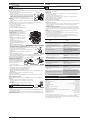
CHANGING THE OIL
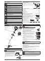
HOLDING THE TRIMMER
WARNING: Always wear eye, hearing, foot and body protection to reduce the risk of injury
when operating this unit.
Before operating the unit, stand in the operating position (Fig. 14). Check for
the following:
• The operator is wearing eye protection and proper clothing
• With a slightly-bent right arm, the operator’s right hand is holding the
shaft grip
• The operator’s left arm is straight, the left hand holding the assist
handle
• The unit is at waist level
• The cutting attachment is parallel to the ground and easily contacts the
grass without the need to bend over
Fig. 14
WARNING: Do not remove or alter the line cutting blade assembly. Excessive line length will make
the clutch overheat. This may lead to serious personal injury or damage to the unit.
TIPS FOR BEST TRIMMING RESULTS
• For best trimming results, operate unit at full throttle.
• Keep the cutting attachment parallel to the ground.
• Do not force the cutting attachment. Allow the tip of the line to do the cutting, especially along walls.
Cutting with more than the tip will reduce cutting efficiency and may overload the engine.
• Cut grass over 8 inches (200 mm) by working from top to bottom in small increments to avoid
premature line wear or engine drag.
• Cutting from left to right improves the unit's cutting efficiency. Clippings are thrown away from the
operator.
• Slowly move the trimmer into and out of the cutting area at the desired height. Move either in a
forward-backward or side-to-side motion. Cutting shorter lengths
produces the best results.
• Trim only when grass and weeds are dry.
• The life of your cutting line is dependent upon proper adherence of
explained trimming techniques, what vegetation is cut, and where
vegetation is cut.
For example, the line will wear faster when trimming against a foundation
wall as opposed to trimming around a tree.
Fig. 15
DECORATIVE TRIMMING
Decorative trimming is accomplished by removing all vegetation around trees, posts, fences and more.
Rotate the whole unit so that the cutting attachment is at a 30° angle to the ground (Fig. 15).
MAINTENANCE AND REPAIR INSTRUCTIONS
CAUTION: Wear gloves to prevent injury when handling the unit.
Change the oil while the engine is still warm. The oil will flow freely and
carry away more impurities.
1. Remove the oil fill plug.
2. Pour the oil out of the oil fill hole and into a container by tipping the unit
Fig. 23
to a vertical position (Fig. 23). Allow ample time for complete drainage.
3. Wipe up any oil residue on the unit and
clean up any oil that may have spilled.
Dispose of the oil according to federal,
state and local regulations.
Fill Line
4. Refill the crankcase with 3.04 fluid ounce
(90 ml) of SAE 30 SF, SG, SH oil. (Fig. 24)
NOTE: Use the bottle and spout saved from
initial use to measure the correct amount
Fig. 25
Fig. 24
of oil. The top of the label on the bottle
measures approximately 3.04 ounces (90 ml) (Fig. 25). Check the level. See Checking the Oil Level. If
the level is low, add a small amount of oil and recheck. Do not overfill (Fig. 25).
5. Replace the oil fill plug.
AIR FILTER MAINTENANCE
Cleaning the Air Filter
Failure to maintain your air filter properly can result in poor performance or
can cause permanent damage to your engine.
1. Open the air filter cover. Push the tab on the under side of the cover
inward. Then pull the air filter cover out and up. (Fig. 26).
2. Remove the air filter (Fig. 26).
3. Wash the filter in detergent and water. Rinse the filter thoroughly and
allow it to dry.
4. Apply enough clean SAE 30 motor oil to lightly coat the filter.
5. Squeeze the filter to spread and remove excess oil.
6. Replace the filter (Fig. 27).
NOTE: If the unit is operated without the air filter, you will VOID the
warranty.
7. Reinstall the air filter cover. Position the slots on the top of the air filter
cover onto the tabs at the top of the back plate (Fig. 26).
8. Swing the cover down until the tab on the air filter backplate snaps into
place in the slot on the air filter cover (Fig. 27).
Air Filter
Cover
Air
Filter
Tab
Fig. 26
Back Plate
Tabs
Air
Filter
Locking Tab
Fig. 27
IDLE SPEED ADJUSTMENT
WARNING: The cutting attachment may spin during idle speed adjustments. Wear
protective clothing and observe all safety instructions to prevent serious personal injury.
MAINTENANCE SCHEDULE
WARNING: To prevent serious injury, never perform maintenance or repairs with unit
running. Always service and repair a cool unit. Disconnect the spark plug wire to ensure
that the unit cannot start.
Perform these required maintenance procedures at the frequency stated in the table. These procedures
should also be a part of any seasonal tune-up.
NOTE: Some maintenance procedures may require special tools or skills. If you are unsure about these
procedures take your unit to any non-road engine repair establishment, individual or authorized service
dealer.
NOTE: Maintenance, replacement, or repair of the emission control devices and system may be
performed by any non-road engine repair establishment, individual or authorized service dealer.
NOTE: Please read the California/EPA statement that came with the unit for a complete listing of terms
and coverage for the emissions control devices, such as the spark arrestor, muffler, carburetor, etc.
FREQUENCY
MAINTENANCE REQUIRED
SEE
Every 10 hours
Clean and oil air filter
p. 5
Change 1st 10 hours
Change oil
p. 5
Every 25 hours
Change oil
Check rocker arm to valve clearance and adjust
Check spark plug condition and gap
p. 5
p. 5
p. 5
FIXED LINE INSTALLATION
WARNING: Never use metal-reinforced line, wire, chain or rope. These can break off and
become dangerous projectiles.
Always use original equipment manufacturer
0.105 inch (2.67 mm) replacement line. Lines
other than those specified may make the
engine overheat or fail.
To install the trimming line:
1. Insert each end of the replacement line
into the holes on either side of retention
hook (Fig. 16).
Fig. 16
2. Push the ends through until they stick out
Fig. 17
of the sides of the head (Fig. 17).
3. Pull the ends through making sure that
the ends are of equal length and the
middle of the line is centered between the
insertion holes (Fig. 18).
4. If the ends are not of equal length, push
the longer end back through the head
part way and pull the shorter end to
compensate. Repeat until both ends are
Fig. 19
Fig. 18
the same length.
5. Push the trimmer line until it lies flat against the cutting head (Fig. 19). Make sure the two lengths of
cutting line are of equal length. If they are not, adjust until they are.
WARNING: Always use the correct line length when installing trimming line on the unit. The
line may not release properly if the line is too long.
CHECKING THE OIL LEVEL
WARNING: To prevent extensive engine wear and damage to the unit, always maintain the
proper oil level in the crankcase. Never operate the unit with a low oil level.
The importance of checking and
maintaining the proper oil level in the
crankcase cannot be overemphasized.
Check oil before each use:
1. Stop the engine and allow oil to drain
into the crankcase.
Max Oil Fill Line
2. Place the engine on a flat, level surface
with the cutting head shield hanging off
Fig. 20
Fig. 21
a work bench or table to get a proper oil
level reading (Fig. 20).
3. Keep dirt, grass clippings and other debris out of the engine. Clean the area around the dipstick
before removing it.
Oil Fill
4. Remove the oil fill plug.
Plug
5. Look into the oil fill hole, use a flashlight if needed. The oil should be
just touching the inner most thread (Fig. 21).
O-Ring
6. If the oil level is not touching the inner most thread on the oil fill hole,
add a small amount of oil to the oil fill hole and recheck (Fig. 22).
Oil Fill
Repeat this procedure until the oil level reaches the inner most thread
Hole
on the oil fill hole.
Fig. 22
NOTE: Do not overfill the unit.
NOTE: Make sure the O-ring is in place on the oil fill plug when checking and changing the oil (Fig. 22).
4
The idle speed of the engine is adjustable. An idle adjustment screw is between the air filter cover and
the engine starter housing (Fig. 28).
NOTE: Careless adjustments can seriously damage your unit. An authorized service dealer should make
carburetor adjustments.
Idle Adjustment Screw
If, after checking the fuel and cleaning the air filter, the engine still will not
idle, adjust the idle speed screw as follows:
1. Start the engine and let it run at a high idle for a minute to warm up.
Refer to Starting/Stopping Instructions.
2. Release the throttle trigger and let the engine idle. If the engine stops,
insert a small Phillips screwdriver in between the air filter cover and the
engine cover (Fig. 43). Turn the idle speed screw in, clockwise, 1/8 of a
turn at a time (as needed) until the engine idles smoothly.
Fig. 28
NOTE: The cutting attachment should not rotate when the engine idles.
3. If the cutting attachment rotates when the engine idles, turn the idle speed screw counterclockwise
1/8 of a turn at a time (as needed), to reduce idle speed.
Checking the fuel, cleaning the air filter, and adjusting the idle speed should solve most engine
problems. If not and all of the following are true:
• the engine will not idle
• the engine hesitates or stalls on acceleration
• there is a loss of engine power
Have the carburetor adjusted by an authorized service dealer.
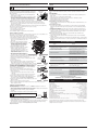
ROCKER ARM CLEARANCE
View Of The Rear Engine Cover
This service requires disassembly of the engine. If feeling
unsure or unqualified to perform this service, take the unit
to an authorized service center.
• The engine must be cold when checking or adjusting Screws
Screws
the valve clearance.
• This task should be performed inside, in a clean, dust
free area.
1. Remove the six (6) screws on the back of the engine
cover with a Flat-head or T-25 Torx screwdriver (Fig. 29).
2. Disconnect the spark plug wire.
3. Clean dirt from around the spark plug. Remove the
spark plug from the cylinder head by turning a 5/8 in.
socket counterclockwise.
4. Remove the engine cover (Fig. 29).
Fig. 29
5. Clean dirt from around the rocker arm cover. Remove
Rocker Arm
the screw holding the rocker arm cover with a large flat blade screwdriver or Torx
Cover
T-25 bit (Fig. 30). Remove the rocker arm cover and gasket.
6. Pull the starter rope slowly to bring the piston to the top of its travel, (known as
Spark
top dead center). Check that:
Plug Hole
• The piston is at the top of its travel while looking in the spark plug hole (Fig. 30).
• Both rocker arms move freely, and both valves are closed.
If these statements are not true, repeat this step.
Fig. 30
7. Slide the feeler gauge between the rocker arm and the valve return
Adjustment
spring. Measure the clearance between the valve stem and rocker arm
Nuts
(Fig. 31). Measure both the intake and exhaust valves.
Intake
Rocker
The recommended clearance for both intake and exhaust is .003 – .006 in. Arms
(.076 – 0.152 mm). Use a standard automotive .005 in. (0.127 mm) feeler
gauge. The feeler gauge should slide between the rocker arm and valve
Exhaust
stem with a slight amount of resistance, without binding. See Figures 32
and 33.
8. If the clearance is not within specification:
Fig. 31
a. Turn the adjusting nut using a 5/16 inch (8 mm) wrench or nut driver
Feeler
(Fig. 31).
Gauge
• To increase clearance, turn the adjusting nut counterclockwise.
• To decrease clearance, turn the adjusting nut clockwise.
0.003–0.006 in.
(0.076–0.152 mm)
b. Recheck both clearances and adjust as necessary.
9. Reinstall the rocker arm cover using a new gasket. Torque the screw to
Valve Stem
20–30 in•lb (2.2–3.4 N•m).
Fig. 32
10. Check the spark plug and reinstall. See Replacing the Spark Plug.
11. Replace the spark plug wire.
12. Reinstall the engine cover. Check alignment of the cover before tightening the screws. Tighten
screws.